Appendix
Set of Building Plans - Four Mile Pub Brewery Addition
July 2, 2013Pages 23–286 sections
Architectural drawings including site sketches, floor plans, and elevation views for the proposed brewery addition at Four Mile House.
Jack James ArchitectFebruary 26, 2013Lot Area 43,275 ft2Proposed building area 6,292 ft2
Lot 12, Section 3, Esquimalt District, Plan 3738 'City of View Royal'
Elevations are in feet. All distances are in metres and decimals thereof unless otherwise indicated.
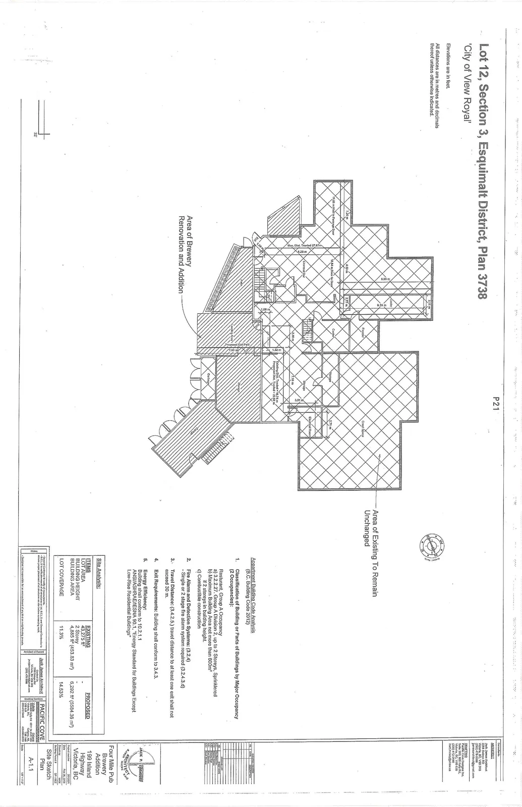
Appartment Building Code Analysis (B.C. Building Code 2012)
- Classification of Building or Parts of Buildings by Major Occupancy (2 Occupancies):
- Restaurant, Group A Occupancy
- a) 3.2.2.27. Group A Division 2, up to 2 Storeys, Sprinklered
- b) Maximum Building Area not more than 600m² if 2 storeys in building height.
- c) Combustible construction
- Fire Alarm and Detection Systems: (3.2.4)
- Single or 2 stage fire alarm system required (3.2.4.3.d)
- Travel Distance: (3.4.2.5) travel distance to at least one exit shall not exceed 30 m.
- Exit Requirements: Building shall conform to 3.4.3.
- Energy Efficiency: Building shall conform to 10.2.1.1 ANSI/ASHRAE/IESNA 90.1, "Energy Standard for Buildings Except Low-Rise Residential Buildings"
Site Analysis
| ITEMS | EXISTING | PROPOSED |
|---|---|---|
| LOT AREA | 43,275 ft² | - |
| BUILDING HEIGHT | 2 Storey | - |
| BUILDING AREA | 4,885 ft² (453.83 m²) | 6,292 ft² (5584.36 m²) |
| LOT COVERAGE | 11.3% | 14.53% |
Project Details:
- Project Name: Four Mile Pub Brewery Addition
- Address: 199 Island Highway Victoria, BC
- Project Number: 2012021
- Date: Feb 26, 2013
- Sheet Number: A-1.1
Page 23–28
Callout of 1st Floor
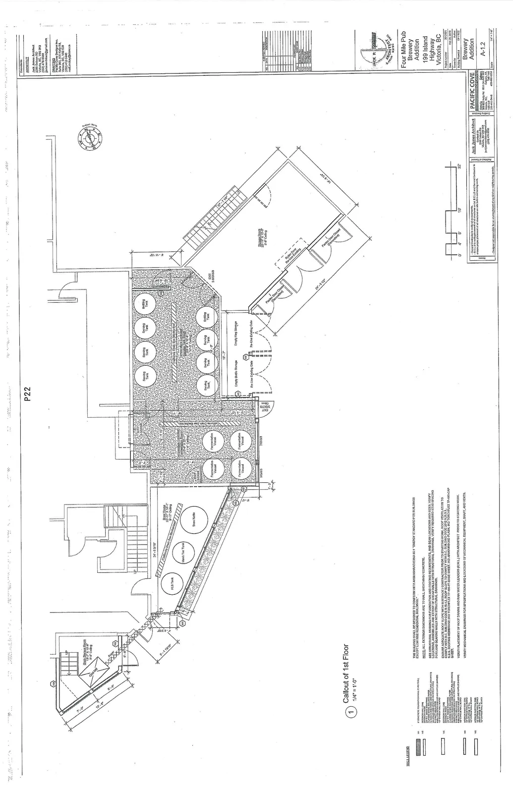
Wall Legend
- W1: 8" CONCRETE FOUNDATION WALL (2 HR. F.R.R.)
- W2: EXTERIOR WALL (2X6)
- EXTERIOR FINISH
- 3/8" P.T. WOOD STRAPPING
- PLYWOOD SHEATHING (OR AS PER STRUCTURAL DRAWINGS)
- 2x6 STUDS (PER SPACING ON STRUCTURAL)
- R-20 BATT INSULATION
- 6 MIL POLYETHYLENE AIR AND VAPOUR BARRIER
- 1/2" GYPSUM WALL BOARD
- W3: EXTERIOR WALL (2X4)
- EXTERIOR FINISH
- 3/8" P.T. WOOD STRAPPING
- BUILDING PAPER
- PLYWOOD SHEATHING (OR AS PER STRUCTURAL DRAWINGS)
- 2x4 STUDS (PER SPACING ON STRUCTURAL)
- R-12 BATT INSULATION
- 6 MIL POLYETHYLENE AIR AND VAPOUR BARRIER
- 1/2" GYPSUM WALL BOARD
- W4: INTERIOR PARTITION (2X6)
- 1/2" GYPSUM WALL BOARD
- 2x6 STUDS @ 16" O.C.
- 1/2" GYPSUM WALL BOARD
- W5: INTERIOR PARTITION (2X4)
- 1/2" GYPSUM WALL BOARD
- 2x4 STUDS @ 16" O.C.
- 1/2" GYPSUM WALL BOARD
General Notes
- THE BUILDING SHALL BE DESIGNED TO CONFORM WITH ANSI/ASHRAE/IESNA 90.1 "ENERGY STANDARD FOR BUILDINGS EXCEPT LOW-RISE RESIDENTIAL BUILDINGS."
- NOTE: ALL EXTERIOR DIMENSIONS ARE TO WALL SHEATHING / CONCRETE.
- SEE STRUCTURAL DRAWING FOR FOUNDATION AND FOOTING REQUIREMENTS, AND BEAM LOCATIONS AND SIZES. VERIFY LOCATIONS, ASSEMBLIES AND EXTENT OF SHEAR WALLS WITH STRUCTURAL DRAWINGS. VERIFY REQUIRED STUD SPACING FOR LOAD BEARING WALLS WITH STRUCTURAL DRAWINGS.
- ENSURE ADEQUATE ROOF SLOPE WITH SUBSTRATE / CONTRACTOR PRIOR TO STARTING WORK. ROOF VENTILATION TO COMPLY WITH B.C. BUILDING CODE 9.19.1.2. ROOF SLOPE TO COMPLY WITH B.C. BUILDING CODE 2012 9.26.3.1. S.B.S. ROOFING MEMBRANE; IKO TORCHFLEX TP-180-FF-BASE SHEET, IKO ARMOURBOND FLASH, IKO TORCHFLEX TP-180-CAP SHEET.
- VERIFY PLACEMENT OF ROOF DRAINS AND RAIN WATER LEADERS (R.W.L.) WITH ARCHITECT PRIOR TO STARTING WORK.
- VERIFY MECHANICAL DRAWINGS FOR SPECIFICATIONS AND LOCATIONS OF MECHANICAL EQUIPMENT, SHAFT, AND VENTS.
Sheet Number: A-1.2
Page 23–28
Brewery Roof
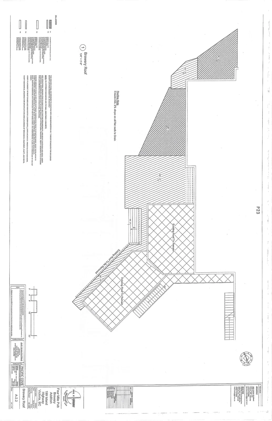
Roofing Note
- Ensure min. 2% slope on all flat roofs to Drain
Sheet Number: A-2.2
Page 23–28
East Elevation
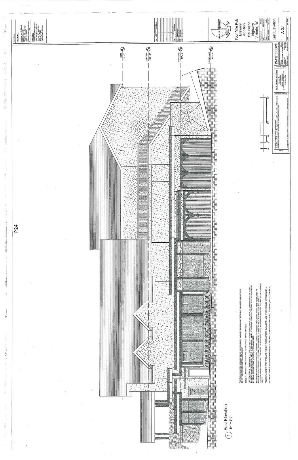
Elevation Levels
- Roof: 116' - 0"
- 2nd Floor: 108' - 0"
- Main Floor: 98' - 0"
- Lower Level: 88' - 6"
Sheet Number: A-3.1
Page 23–28
South Elevation
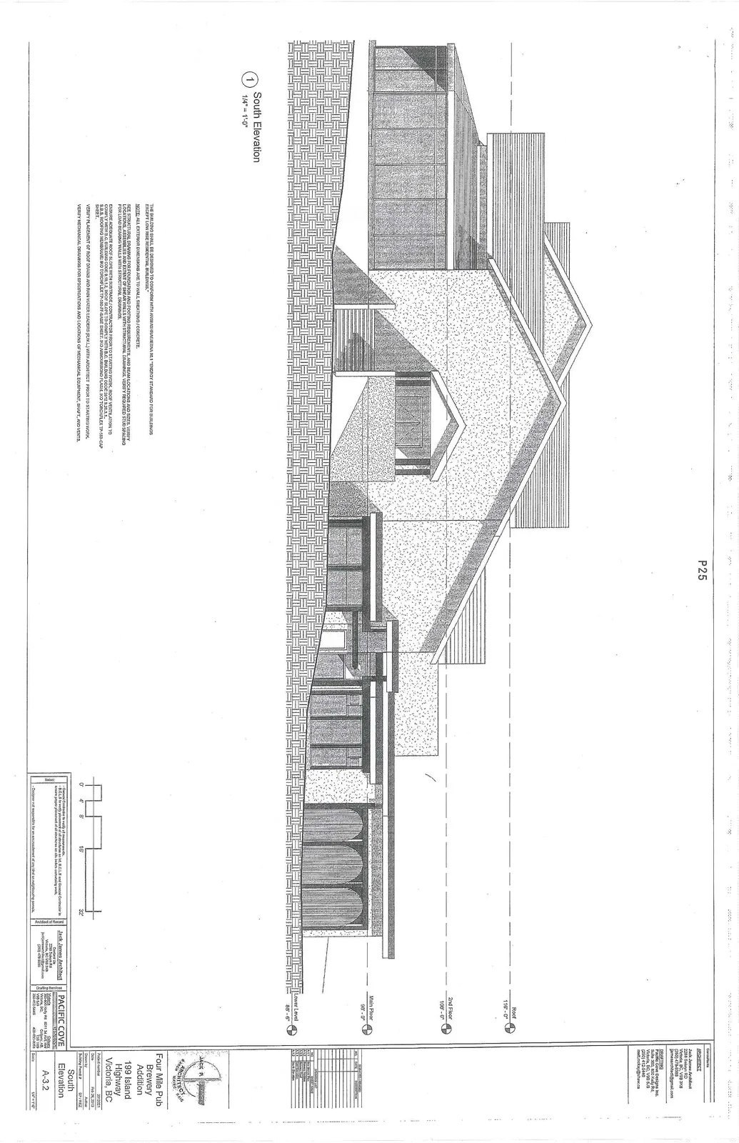
Elevation Levels
- Roof: 116' - 0"
- 2nd Floor: 108' - 0"
- Main Floor: 98' - 0"
- Lower Level: 88' - 6"
Sheet Number: A-3.2
Page 23–28
North Elevation
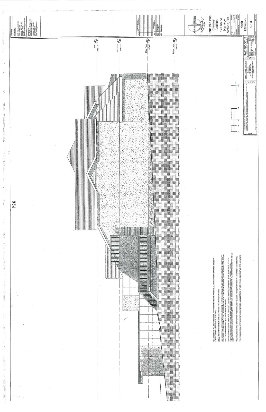
Elevation Levels
- Roof: 116' - 0"
- 2nd Floor: 108' - 0"
- Main Floor: 98' - 0"
- Lower Level: 88' - 6"
Sheet Number: A-3.3
Page 23–28
Extracted from: 2013 07 02 Council Agenda