Appendix
Eagle Creek Village Servicing Plan (Attachment 42)
December 10, 2013Page 561 section
Engineering site plan showing the layout of utility services including water, gas, hydro, and storm drainage systems.
Westbrook Consulting Ltd.Drawing 2823-DP01May 2012
Servicing Plan - Eagle Creek Village
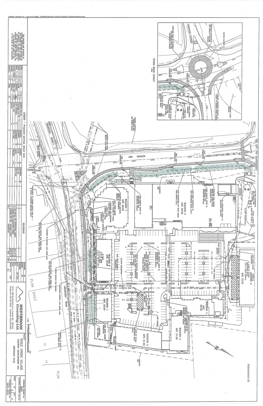
Legend - Proposed services shown bold
| Symbol | Description | Symbol | Description | Symbol | Description |
|---|---|---|---|---|---|
| WATER —W— | WATER | GAS —G— | EXISTING U/G UTIL. | MANHOLE | HYDRANT |
| SEWER —S— | SEWER | CURB | PROPOSED U/G UTIL. | CLEANOUT | VALVE |
| DRAIN —D— | DRAIN | SIDEWALK | LIGHT STANDARD | CATCHBASIN | METER |
| NATURAL GRADE | NATURAL GRADE | EDGE PAVE. | POWER POLE | ROAD SIGN | REDUCER |
| CULVERT | CULVERT | BUSHLINE | ANCHOR | MONUMENT | LOT PIN |
| HEADWALL | HEADWALL | TREE | LEAD PLUG |
Revisions
| No. | Description | Date | By | Appd. |
|---|---|---|---|---|
| 1 | REVISED FOR NEW BUILDING LAYOUT | 2012-05-15 | BJL | FC |
| 2 | ISSUED FOR DEVELOPMENT PERMIT | 2013-01-25 | BJL | FC |
| 3 | RE-ISSUED FOR DEVELOPMENT PERMIT | 2013-10-30 | BJL | FC |
Project Information
- Project: Eagle Creek Village, Omicron Development Inc.
- Drawing Title: Servicing Plan
- Consulting Firm: Westbrook Consulting Ltd. (#115 - 850 Goldstream Ave., Victoria, BC V9B 0J3; Tel: 250-391-8532; Fax: 250-391-8593)
- Westbrook Project No.: 2823
- Drawing No.: 2823-DP01
- Sheet: 1 of 3
- Date: MAY 2012
- Designed: KS
- Checked: FC
- Drawn: BJL
- Scale: Horiz. 1:500; Vert. N/A
Key Plan Notes and Labels
- Building Elevations (MFE):
- Building 1: MFE 20.00
- Building 2: MFE 21.00
- Building 3: MFE 21.00
- Building 4: MFE 22.00
- Building 5: MFE 23.00
- Building 6: MFE 20.00
- Building 7: MFE 20.00
- Building 8: MFE 20.00
- Utility & Infrastructure Callouts:
- Storm Drain Outlet (Scale 1:500)
- Proposed Rain Garden. Refer to Storm Water Management Plan.
- Oil/Grit Interceptor (multiple locations)
- Rain Water Leader Connection (multiple locations)
- Fire Hydrant. Refer to mechanical for connection details. (multiple locations)
- Existing cathodic protection for CRD supply mains.
- Proposed CRD pressure reducing station.
- Headwall at outlet to rain garden (Typ.).
- Retain existing fire hydrant.
- Replace existing 150ø sewer main with 200ø PVC DR35 at lower grade.
- Reconnect to existing 150ø water main.
- Reconnect to existing supply main No. 1 & install pressure reducing valve.
- 150ø perforated PVC drain under rain garden (Typ.).
- Lawn basin connected to 150ø perforated drain (Typ.).
General Note: THE LOCATION AND ELEVATION OF EXISTING UNDERGROUND SERVICES ON THIS DRAWING ARE NOT NECESSARILY OR COMPLETE. THE ACTUAL HORIZONTAL AND VERTICAL LOCATIONS MUST BE CONFIRMED BY UTILITY COMPANIES AND THE CONTRACTOR PRIOR TO THE START OF ANY EXCAVATIONS.
Page 56
Extracted from: 2013 12 10 Council Agenda