Capital Regional District Bicycle Wayfinding Guidelines Draft 1 March 2014
Extensive design and planning document outlining the standards for a consistent regional bicycle wayfinding signage system across the CRD.
Capital Regional District Bicycle Wayfinding Guidelines
Draft 1 March 2014

Adapted from original guidance produced for and under the permission of TransLink. Original and adapted document prepared by Applied and Alta Planning+Design, 2014.
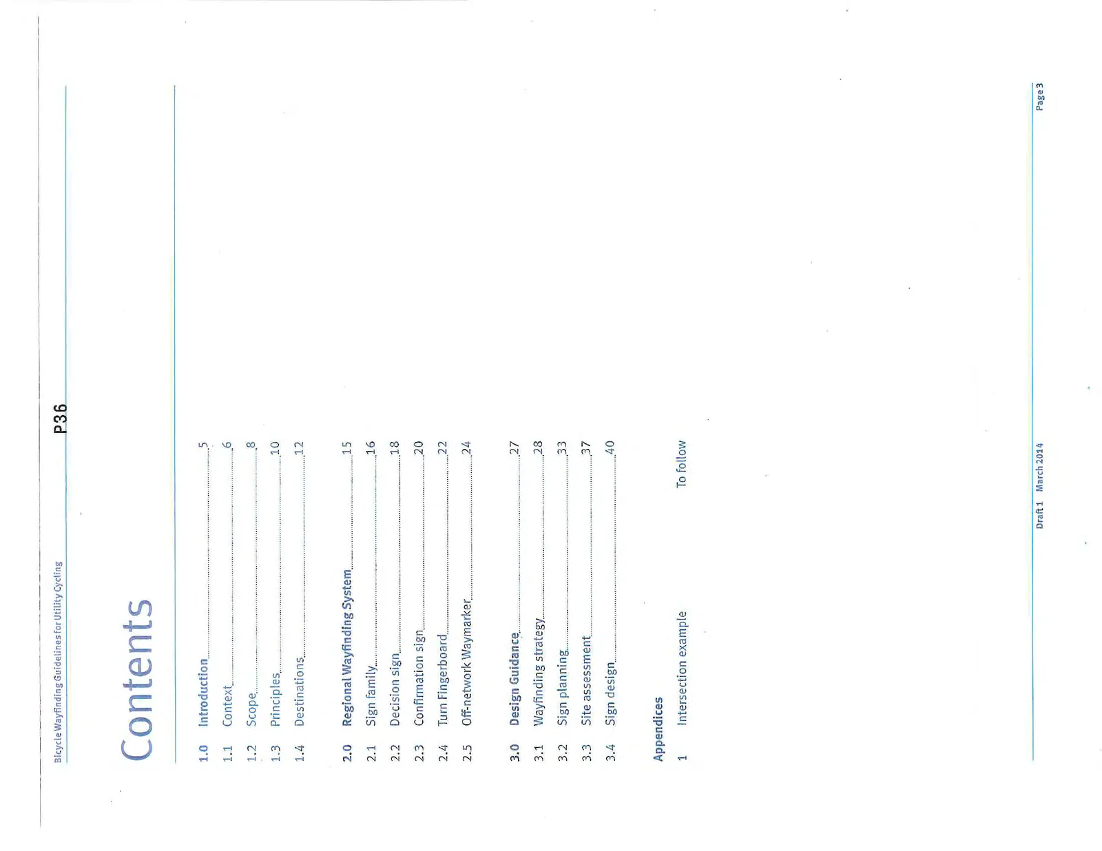
Contents
- 1.0 Introduction - 5
- 1.1 Context - 6
- 1.2 Scope - 8
- 1.3 Principles - 10
- 1.4 Destinations - 12
- 2.0 Regional Wayfinding System - 15
- 2.1 Sign family - 16
- 2.2 Decision sign - 18
- 2.3 Confirmation sign - 20
- 2.4 Turn Fingerboard - 22
- 2.5 Off-network Waymarker - 24
- 3.0 Design Guidance - 27
- 3.1 Wayfinding strategy - 28
- 3.2 Sign planning - 33
- 3.3 Site assessment - 37
- 3.4 Sign design - 40
- Appendices
- 1 Intersection example - To follow
1.0 Introduction
Explaining the purpose, benefits and background to the bicycle wayfinding guidelines.
1.1 Context
Pedestrian & Cycling Master Plan (PCMP)
These guidelines form one of the actions described in the Capital Regional District (CRD) Pedestrian & Cycling Master Plan (PCMP), published in March 2010.
The PCMP envisions a region where 15 percent of trips are made by walking and 15 percent are made by cycling, with higher projected cycling rates (25 percent) within urban centres. If successful, thousands more people will be starting to cycle to work, to school, and for other normal journeys over the next three decades. The PCMP will enable many of these journeys to occur on bicycle routes that are comfortable for most, if not all, levels of experience.
One of the components of a comfortable network is provision of good quality signage to guide new and existing cyclists to their destinations. Strategy 3.2 of the PCMP describes ways to develop a common regional wayfinding system for cycling.
Relationship to existing guidance
These guidelines are intended to provide planning and design advice for bicycle wayfinding across the Capital Regional District. Other types, including warning and regulatory signs, are covered by the Transportation Association of Canada (TAC) and BC Ministry of Transportation and Infrastructure (BC MoTI).
The current edition of the TAC Bikeway Traffic Control Guidelines for Canada provides specific guidance on signage and markings for bicycle facilities. Similar guidelines from the BC MoTI are forthcoming.
This document supplements these national and provincial guidelines providing additional advice, details and solutions to circumstances common to the Capital Regional District.
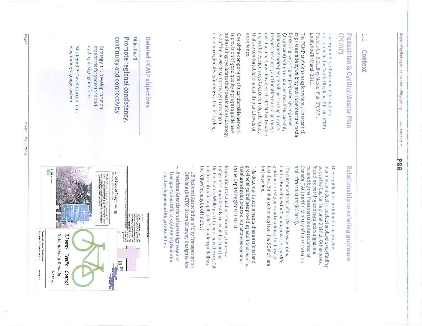
In addition to Canadian references, there is a range of compatible advice available from the United States. While practitioners must be careful not to contradict applicable Canadian guidelines the following may be of interest:
- US National Association of City Transportation Officials (NACTO) Urban Bikeway Design Guide
- American Association of State Highway and Transportation Officials (AASHTO) Guide for the Development of Bicycle Facilities
Related PCMP objectives
Objective 3 Promote regional consistency, continuity and connectivity
Strategy 3.1: Develop common standards for pedestrian and cycling design guidelines
Strategy 3.2: Develop a common wayfinding signage system
What are the benefits of wayfinding?
Wayfinding is a decision-making process related to navigation. The decisions we make are influenced by what we sense, our experience and the information we can obtain. Signage, maps and mobile devices, are commonly recognized means of assessing wayfinding information.
Cycling and walking are promoted modes as they are efficient, economical, healthy and sustainable choices for many journeys. The CRD expects that, by 2038, 1.7 million trips will occur in the region daily. 255,000 of these trips (15 percent) will occur by bike and a further 255,000 will occur by walking (totaling 510,000 daily trips).
Many of these potential walking and cycling trips will be made by people new to cycling and walking. For them the wayfinding process will be more conscious as they may not know the active travel network or understand what distances they are capable of traveling.
Much of the region's hundreds of kilometres of active travel facilities are on residential streets, separated paths or special routes that a driver or transit user might be unaware of. This network can provide safe, comfortable and convenient access across the region but only if pedestrians and cyclists can find their way to it and through it.
A wayfinding system can help users by identifying the active travel network, pointing out route options and helping them learn what other destinations could be accessed.
How these guidelines were developed
The guidelines were prepared by CRD in consultation with municipal representatives throughout the region.
Municipal representatives contributed comments, questions and recommendations at various stages in the writing of the guidelines.
The Regional Bicycle Wayfinding Guidelines will be reviewed and updated from time to time to ensure that they remain compatible with current guidance produced by other bodies. Municipal representatives will be involved in this process to ensure that the guidelines remain consistent and appropriate for the needs of those agencies responsible for delivering cycling projects across the region.
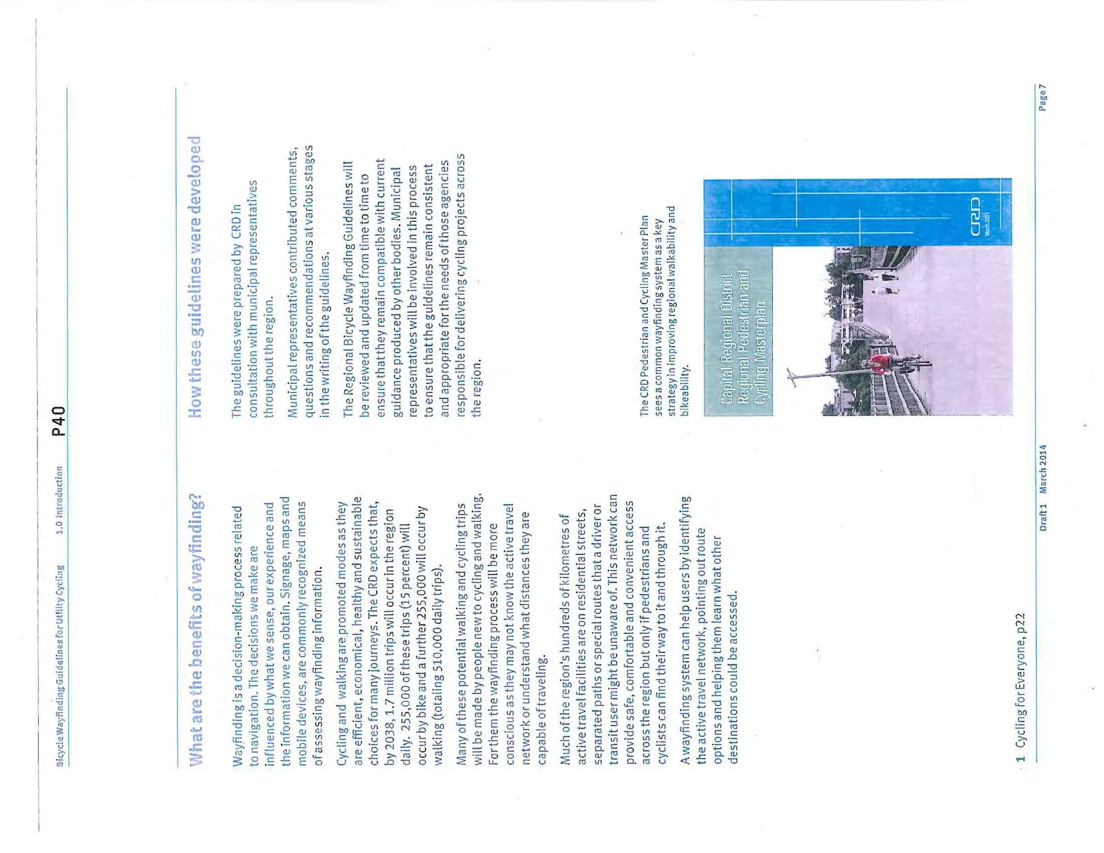
The CRD Pedestrian and Cycling Master Plan sees a common wayfinding system as a key strategy in improving regional walkability and bikeability.
1.2 Scope
Identifying the user
These guidelines are focused on helping achieve the goals of the CRD Pedestrian and Cycling Master Plan (PCMP). In particular, they aim to support a mode shift towards cycling for trips for suitable everyday trips.
The wayfinding guidelines accommodate this focus by prioritizing directions to places that many people visit for a wide variety of purposes, that are a moderate distance apart and those that can be accessed from the designated bike network.
By implication the guidelines are not specifically intended for recreational cycling, which includes cycling on trails, sports cycling or long distance touring, since these do not directly encourage mode shift for everyday trips. However, CRD acknowledges the value of information for recreation and other uses, such as cycle tourism as part of a supportive framework and the economy of the region. The guidelines therefore include principles and advice that may be a useful reference for other forms of cyclist wayfinding.
Wayfinding for walking
Walkers and cyclists have very different needs when wayfinding.
A cyclist can travel much further and faster than a walker for the same effort. This produces large differences in how far away a destination might be reasonably signed from. Walkers are also more willing to stop and study information, whereas maps, detailed directions and smaller text are difficult to use while cycling. As with driving a bicycle wayfinding system must consider safe use and refrain from including too much text on any one sign.
For these reasons the guidelines do not attempt to combine cycling and walking wayfinding in a single approach. However, the presence of cyclist-focused wayfinding on shared routes will undoubtedly provide benefits to other users. This could be supplemented for walking by adding maps and specific directions to local destinations within short, walkable distances.
Types of cyclist
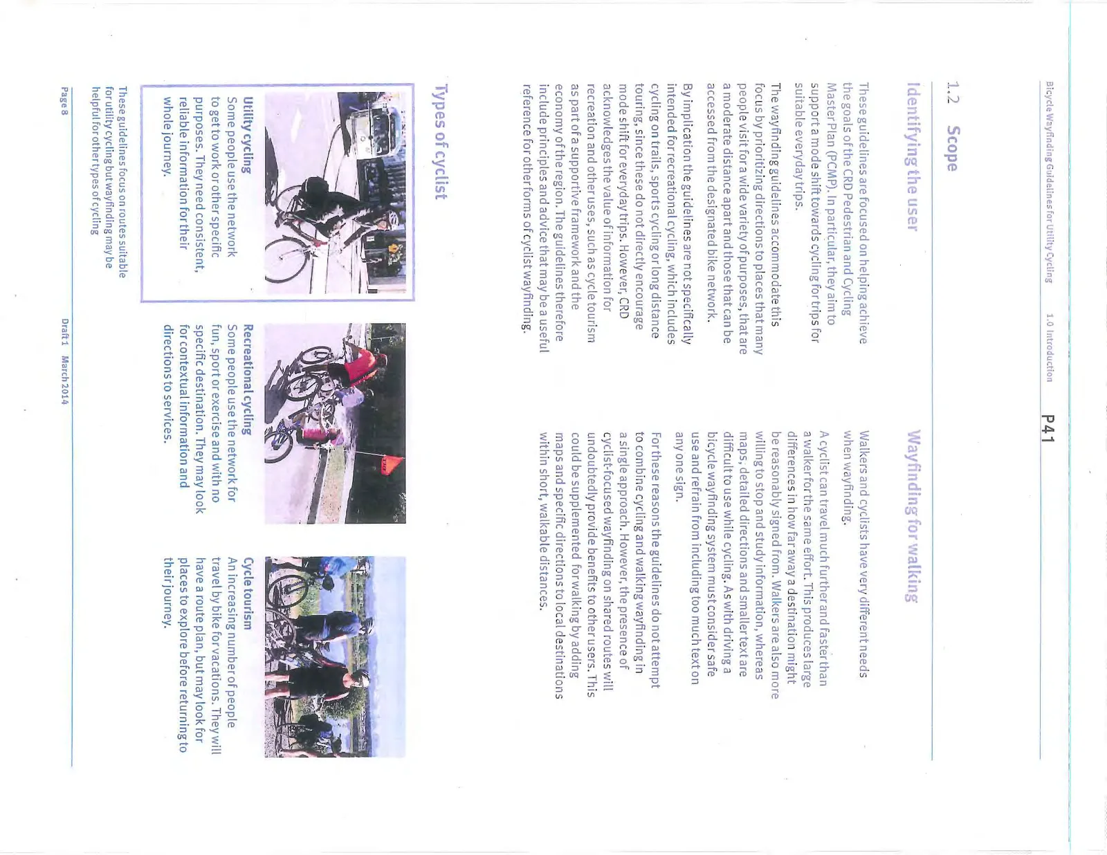
- Utility cycling: Some people use the network to get to work or other specific purposes. They need consistent, reliable information for their whole journey.
- Recreational cycling: Some people use the network for fun, sport or exercise and with no specific destination. They may look for contextual information and directions to services.
- Cycle tourism: An increasing number of people travel by bike for vacations. They will have a route plan, but may look for places to explore before returning to their journey.
These guidelines focus on routes suitable for utility cycling but wayfinding may be helpful for other types of cycling.
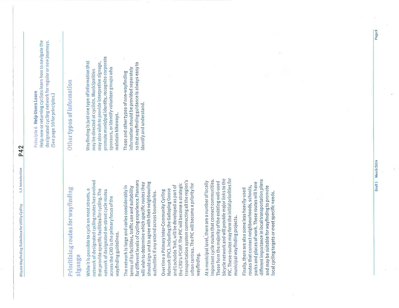
Prioritizing routes for wayfinding signage
While it is possible to cycle on most streets, a network of designated cycling routes has evolved that provide specific facilities for cycling. The network of designated on-street cycle routes across the CRD is the primary focus of the wayfinding guidelines.
The network is large and varies considerably in terms of its facilities, traffic use and suitability for different levels of cycling experience. Planners will wish to determine which specific routes they should sign and to agree with their neighbouring authorities if any extend across boundaries.
Over time a Primary Inter-Community Cycling Network (PIC), including the Galloping Goose and Lochside Trail, will be developed as part of the CRD's PCMP. The PIC will become a strategic transportation system connecting all the region's urban centres. The PIC will become a priority for wayfinding.
At a municipal level, there are a number of locally important cycle routes that connect communities. These form the majority of the existing well-used bicycle network and will provide major links to the PIC. These routes may form the initial priorities for municipal wayfinding projects.
Finally, there are also some less heavily-used routes that connect neighbourhoods, schools, parks and places of work. These routes will have different importance in local transportation plans and may be suitable for wayfinding to promote local cycling targets or meet specific needs.
Other types of information
Wayfinding is just one type of information that may be directed at cyclists. Municipalities may also wish to provide interpretive signage, promote municipal identity, recognize corporate sponsors, or identify volunteer groups who maintain bikeways.
These and other types of non-wayfinding information should be provided separately so that wayfinding guidance is always easy to identify and understand.
Principle 6 Help Users Learn: Help new or returning cyclists learn how to navigate the designated cycling network for regular or new journeys.
1.3 Principles
These Guidelines will be formulated around a set of core design principles. These principles are included to describe the basis for achieving a fundamentally consistent approach.
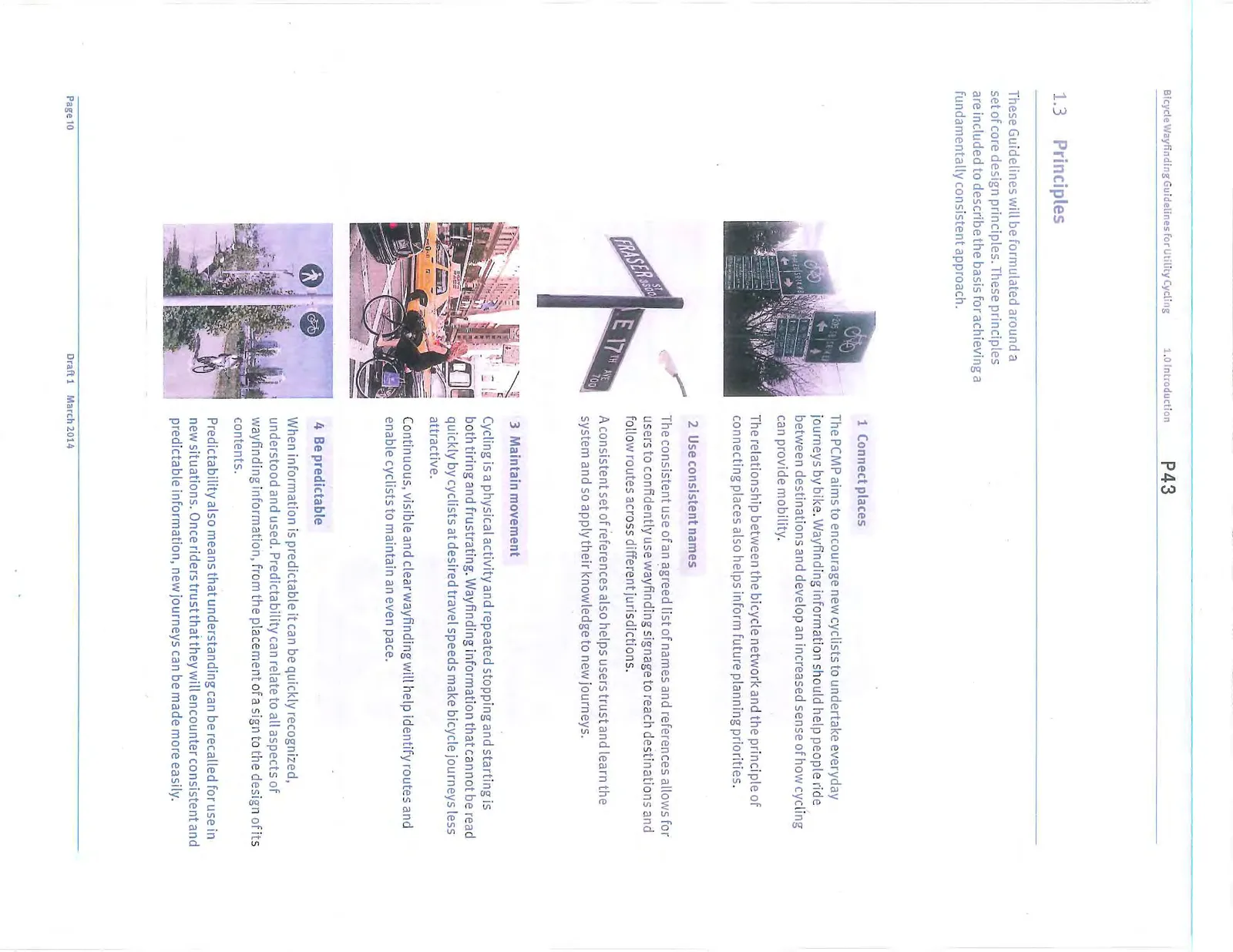
1 Connect places The PCMP aims to encourage new cyclists to undertake everyday journeys by bike. Wayfinding information should help people ride between destinations and develop an increased sense of how cycling can provide mobility. The relationship between the bicycle network and the principle of connecting places also helps inform future planning priorities.
2 Use consistent names The consistent use of an agreed list of names and references allows for users to confidently use wayfinding signage to reach destinations and follow routes across different jurisdictions. A consistent set of references also helps users trust and learn the system and so apply their knowledge to new journeys.
3 Maintain movement Cycling is a physical activity and repeated stopping and starting is both tiring and frustrating. Wayfinding information that cannot be read quickly by cyclists at desired travel speeds make bicycle journeys less attractive. Continuous, visible and clear wayfinding will help identify routes and enable cyclists to maintain an even pace.
4 Be predictable When information is predictable it can be quickly recognized, understood and used. Predictability can relate to all aspects of wayfinding information, from the placement of a sign to the design of its contents. Predictability also means that understanding can be recalled for use in new situations. Once riders trust that they will encounter consistent and predictable information, new journeys can be made more easily.
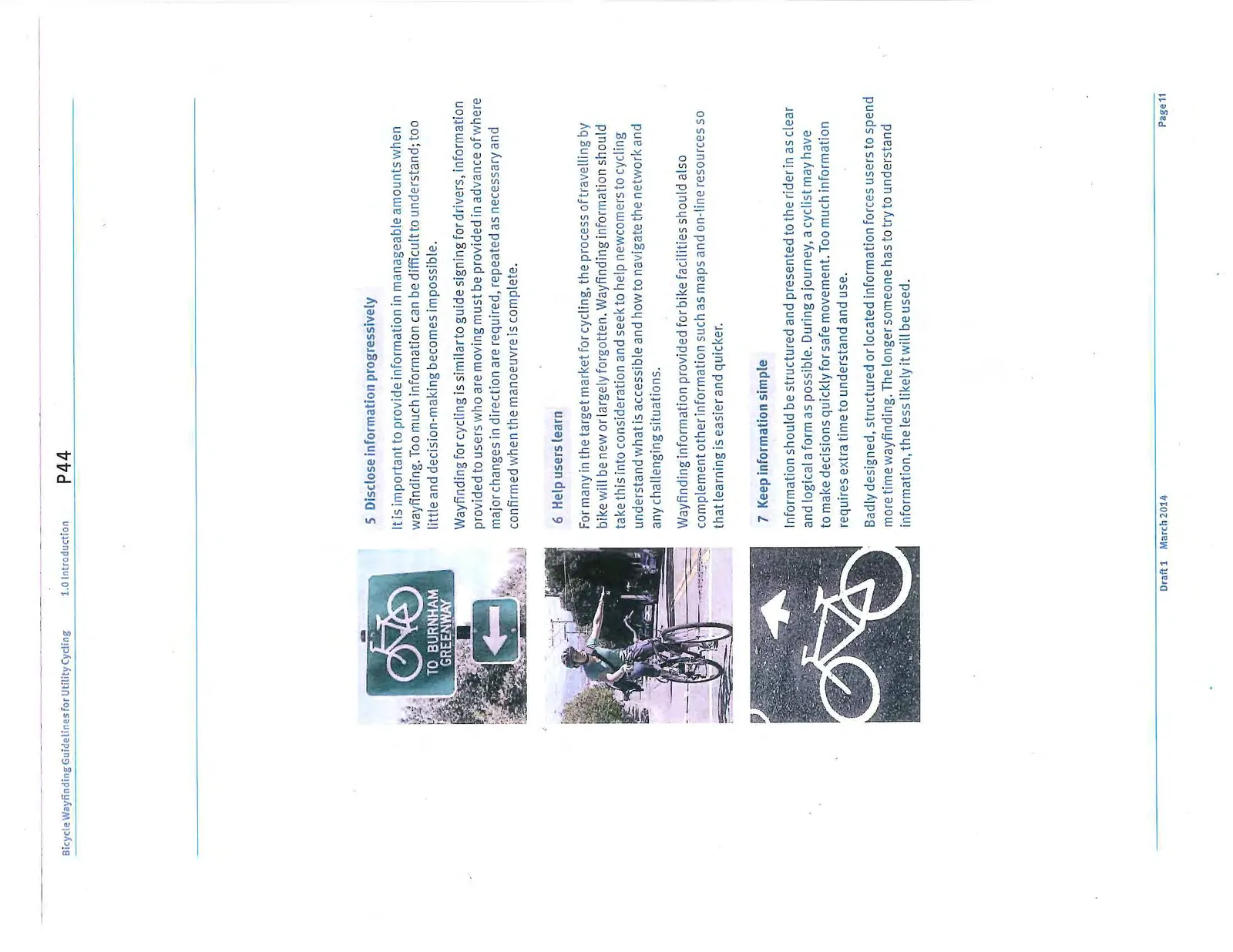
5 Disclose information progressively It is important to provide information in manageable amounts when wayfinding. Too much information can be difficult to understand; too little and decision-making becomes impossible. Wayfinding for cycling is similar to guide signing for drivers, information provided to users who are moving must be provided in advance of where major changes in direction are required, repeated as necessary and confirmed when the manoeuvre is complete.
6 Help users learn For many in the target market for cycling, the process of travelling by bike will be new or largely forgotten. Wayfinding information should take this into consideration and seek to help newcomers to cycling understand what is accessible and how to navigate the network and any challenging situations. Wayfinding information provided for bike facilities should also complement other information such as maps and on-line resources so that learning is easier and quicker.
7 Keep information simple Information should be structured and presented to the rider in as clear and logical a form as possible. During a journey, a cyclist may have to make decisions quickly for safe movement. Too much information requires extra time to understand and use. Badly designed, structured or located information forces users to spend more time wayfinding. The longer someone has to try to understand information, the less likely it will be used.
1.4 Destinations
Destination hierarchy
Following from the first principle, "Connect Places", the major focus of these guidelines is how to direct cyclists along the designated cycling network to the places they want to go. In order to do this, a set of destinations and their names must be agreed regionally. It is a fundamental user-expectation that wayfinding will refer to destinations consistently and predictably until they are reached.
A hierarchy of destinations is necessary in order to prioritize which destinations to include when there are too many possible destinations than can fit legibly on a sign. In preparing these guidelines, municipalities have agreed to the following hierarchy.
Level 1 - Urban Centres These are the major centres of activity described in the Regional Sustainability Strategy. The Urban Centres are the main centres within individual municipalities offering a full range of attractions and services, and provide the primary geographic orientation points for regional cycling.
Level 1 destinations are included on signs up to 8 kilometres away, the distance for approximately 90 percent of all current utilitarian bicycle trips in the CRD. The map on the following page shows the suggested Level 1 destinations and an 8 kilometre scale bar for reference.
Level 2 - Local Neighbourhoods These represent centres of community with sub-regional importance. Local Neighbourhoods provide a mixture of services used by local people and should be determined in alignment with local Official Community Plans.
Level 2 destinations are included on signs up to 4 kilometres away.
Level 3 - Major Attractions These trip attractors include transit stations and exchanges, major tourist venues, regional parks, post-secondary education institutions and the region's border crossings. These should be determined from regionally agreed resources.
Level 3 destinations are included on signs up to 2 kilometres away.
Level 4 - Local Destinations A municipality may wish to increase wayfinding to include local destinations. This may be useful to reflect the nature of lower density areas or to integrate bicycle wayfinding with walking wayfinding on shared paths. They may also be useful if a municipality wishes to provide wayfinding signage on a route that does not connect Level 1-3 destinations (which should take priority on wayfinding signage).
It is not practical to list all the possible local destinations across the region, but the following represents some classifications that may be useful:
- Recreational cycle paths
- Shopping centres
- Business parks
- Parks, open spaces and sports facilities
- High schools
- Landmarks
- Healthcare facilities
- Public washrooms
- Bicycle repair shops
- Civic facilities – community centres, libraries
While there is value in increased information it is important to consider the principle of keeping information simple. Overloading signs with information while well-intentioned can easily have the effect of making them harder to understand and therefore less useful.
Level 4 destinations are included on signs up to 2 kilometres away.
Destination hierarchy: It is a fundamental user-expectation that wayfinding will refer to destinations consistently and predictably until they are reached.
Principle 1 Connect Places: Encourage new cyclists to undertake journeys by bike instead of less sustainable modes. (See page 10 for principles.)
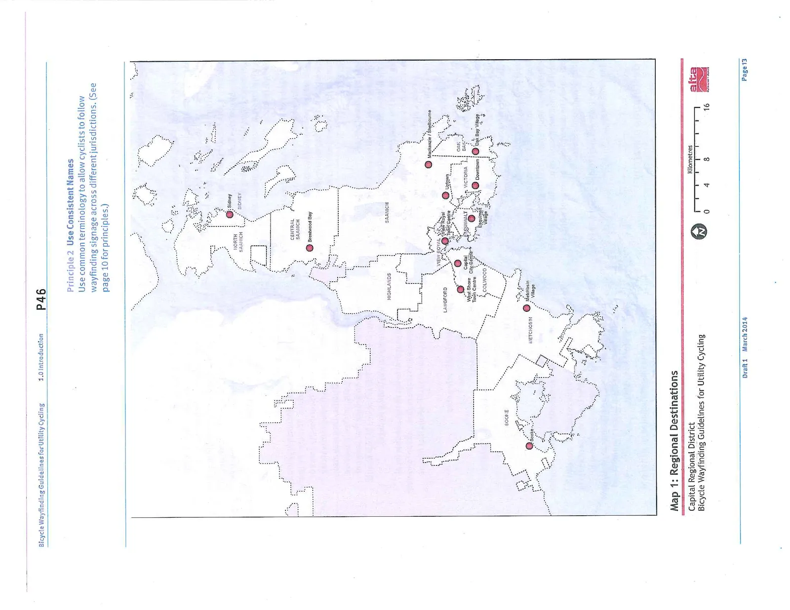
Principle 2 Use Consistent Names: Use common terminology to allow cyclists to follow wayfinding signage across different jurisdictions. (See page 10 for principles.)
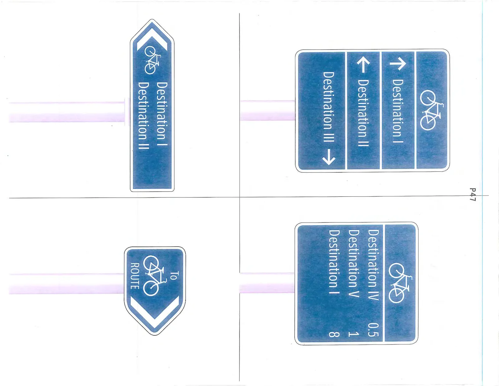
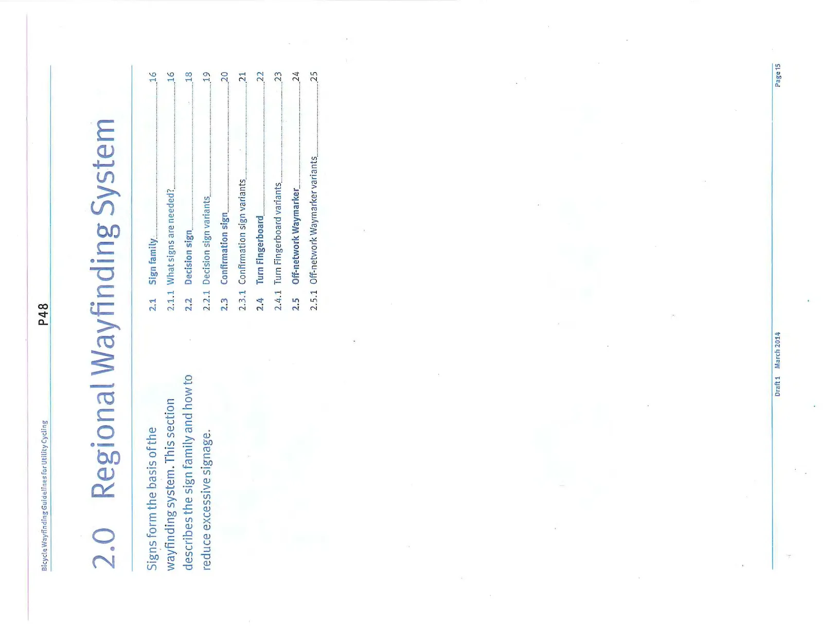
2.0 Regional Wayfinding System
Signs form the basis of the wayfinding system. This section describes the sign family and how to reduce excessive signage.
2.1 Sign family
2.1.1 What signs are needed?
3 Part system On connections to and from regional routes
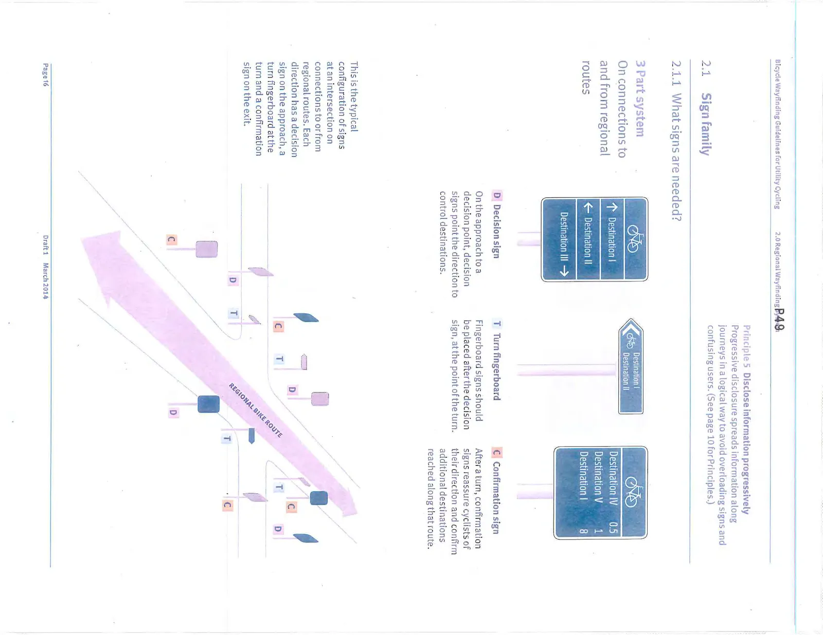
- D Decision sign: On the approach to a decision point, decision signs point the direction to control destinations.
- T Turn fingerboard: Fingerboard signs should be placed after the decision sign, at the point of the turn.
- C Confirmation sign: After a turn, confirmation signs reassure cyclists of their direction and confirm additional destinations reached along that route.
This is the typical configuration of signs at an intersection on connections to or from regional routes. Each direction has a decision sign on the approach, a turn fingerboard at the turn and a confirmation sign on the exit.
2 Part system On all other routes
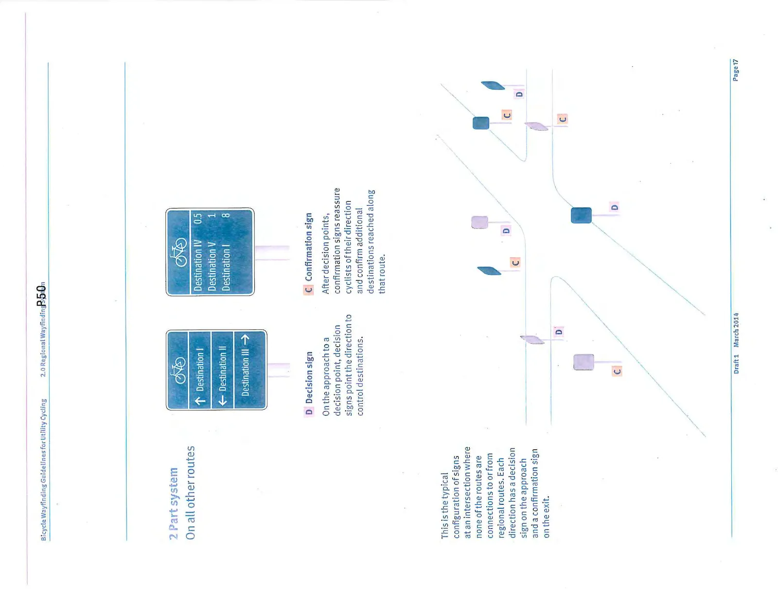
- D Decision sign: On the approach to a decision point, decision signs point the direction to control destinations.
- C Confirmation sign: After decision points, confirmation signs reassure cyclists of their direction and confirm additional destinations reached along that route.
This is the typical configuration of signs at an intersection where none of the routes are connections to or from regional routes. Each direction has a decision sign on the approach and a confirmation sign on the exit.
Principle 5 Disclose information progressively: Progressive disclosure spreads information along journeys in a logical way to avoid overloading signs and confusing users. (See page 10 for Principles.)
2.2 Decision Sign
Decision signs provide directions to selected destinations. They are located in advance of intersections to provide cyclists the time to slow and manoeuvre if necessary.
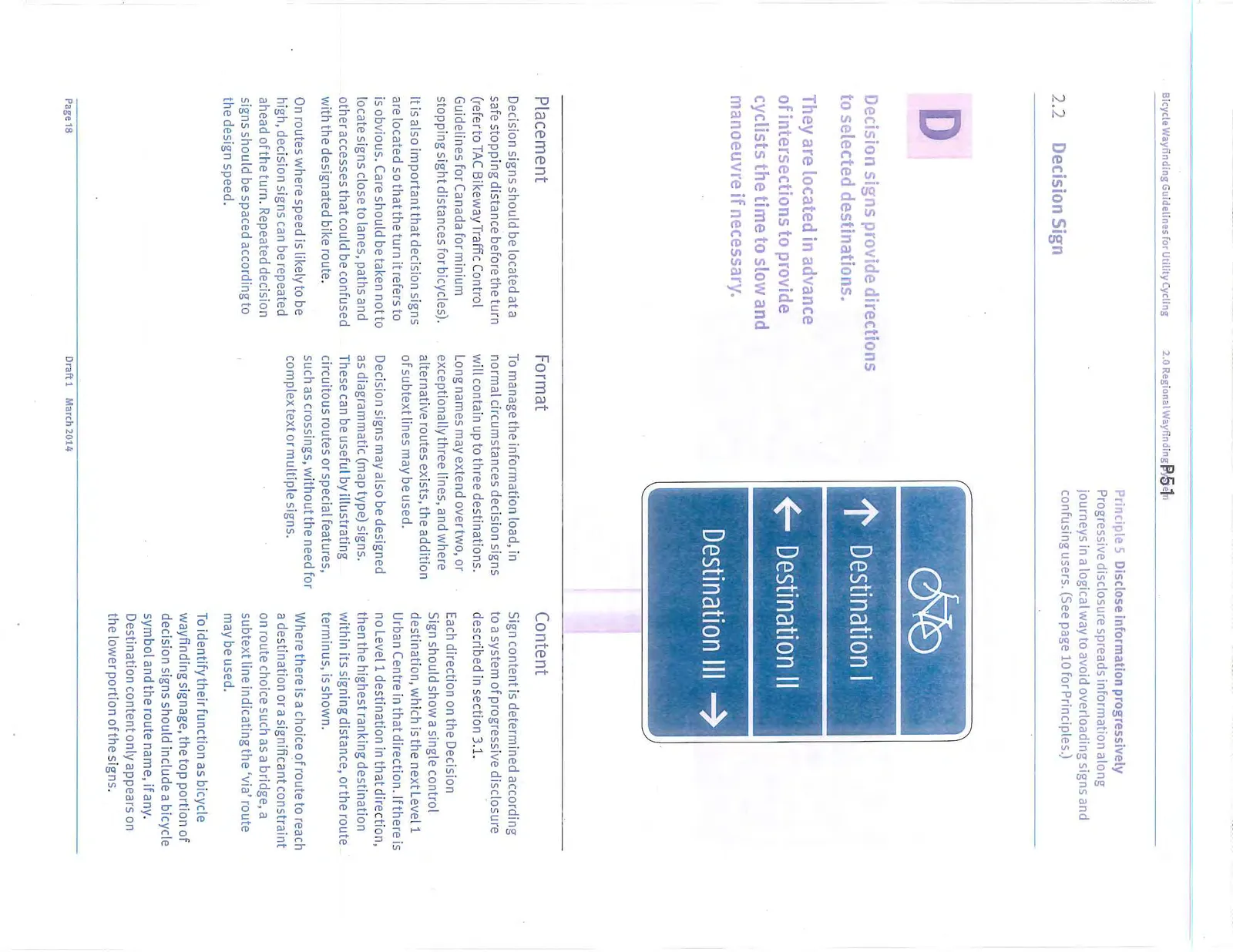
Placement
Decision signs should be located at a safe stopping distance before the turn (refer to TAC Bikeway Traffic Control Guidelines for Canada for minimum stopping sight distances for bicycles).
It is also important that decision signs are located so that the turn it refers to is obvious. Care should be taken not to locate signs close to lanes, paths and other accesses that could be confused with the designated bike route.
On routes where speed is likely to be high, decision signs can be repeated ahead of the turn. Repeated decision signs should be spaced according to the design speed.
Format
To manage the information load, in normal circumstances decision signs will contain up to three destinations. Long names may extend over two, or exceptionally three lines, and where alternative routes exists, the addition of subtext lines may be used.
Decision signs may also be designed as diagrammatic (map type) signs. These can be useful by illustrating circuitous routes or special features, such as crossings, without the need for complex text or multiple signs.
Content
Sign content is determined according to a system of progressive disclosure described in section 3.1.
Each direction on the Decision Sign should show a single control destination, which is the next Level 1 Urban Centre in that direction. If there is no Level 1 destination in that direction, then the highest ranking destination within its signing distance, or the route terminus, is shown.
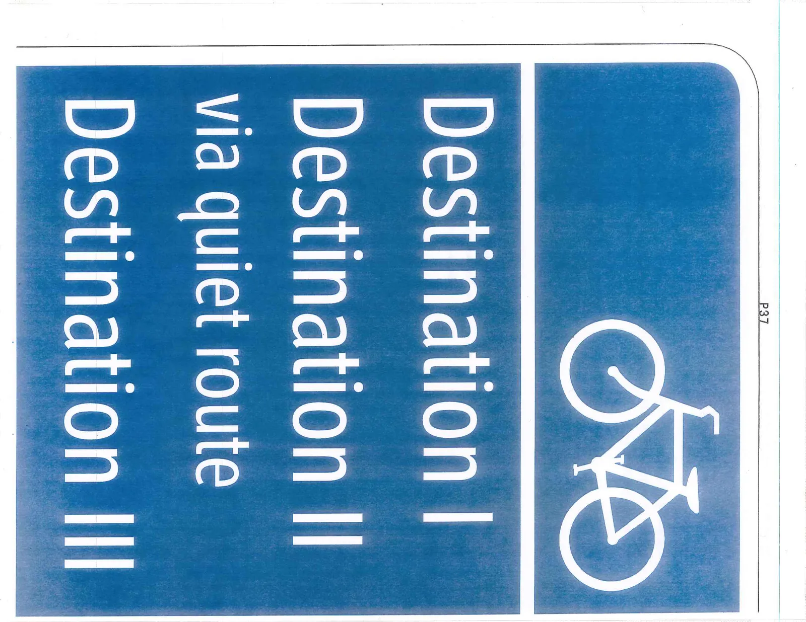
Where there is a choice of route to reach a destination or a significant constraint on route choice such as a bridge, a subtext line indicating the ‘via’ route may be used.
To identify their function as bicycle wayfinding signage, the top portion of decision signs should include a bicycle symbol and the route name, if any. Destination content only appears on the lower portion of the signs.
2.2.1 Decision Sign Examples
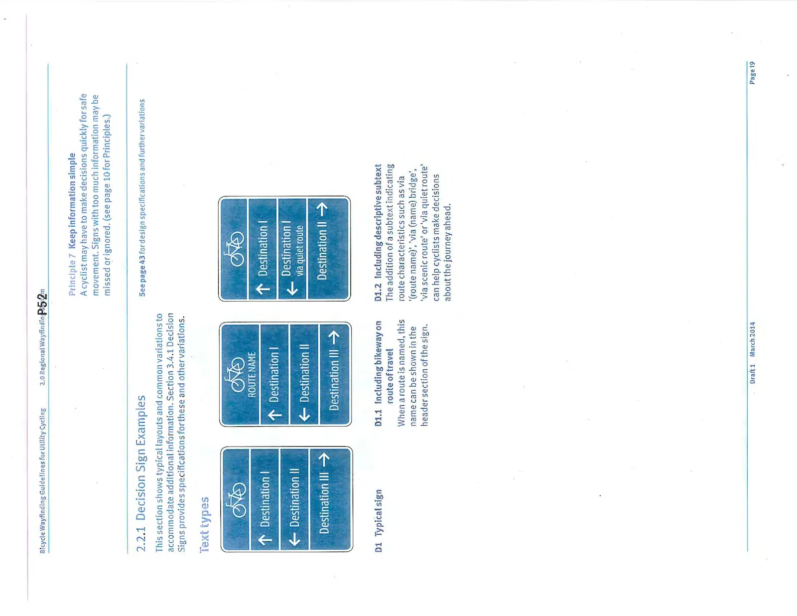
- D1 Typical sign
- D1.1 Including bikeway on route of travel: When a route is named, this name can be shown in the header section of the sign.
- D1.2 Including descriptive subtext: The addition of a subtext indicating route characteristics such as via '(route name)', 'via (name) bridge', 'via scenic route' or 'via quiet route' can help cyclists make decisions about the journey ahead.
2.3 Confirmation Sign
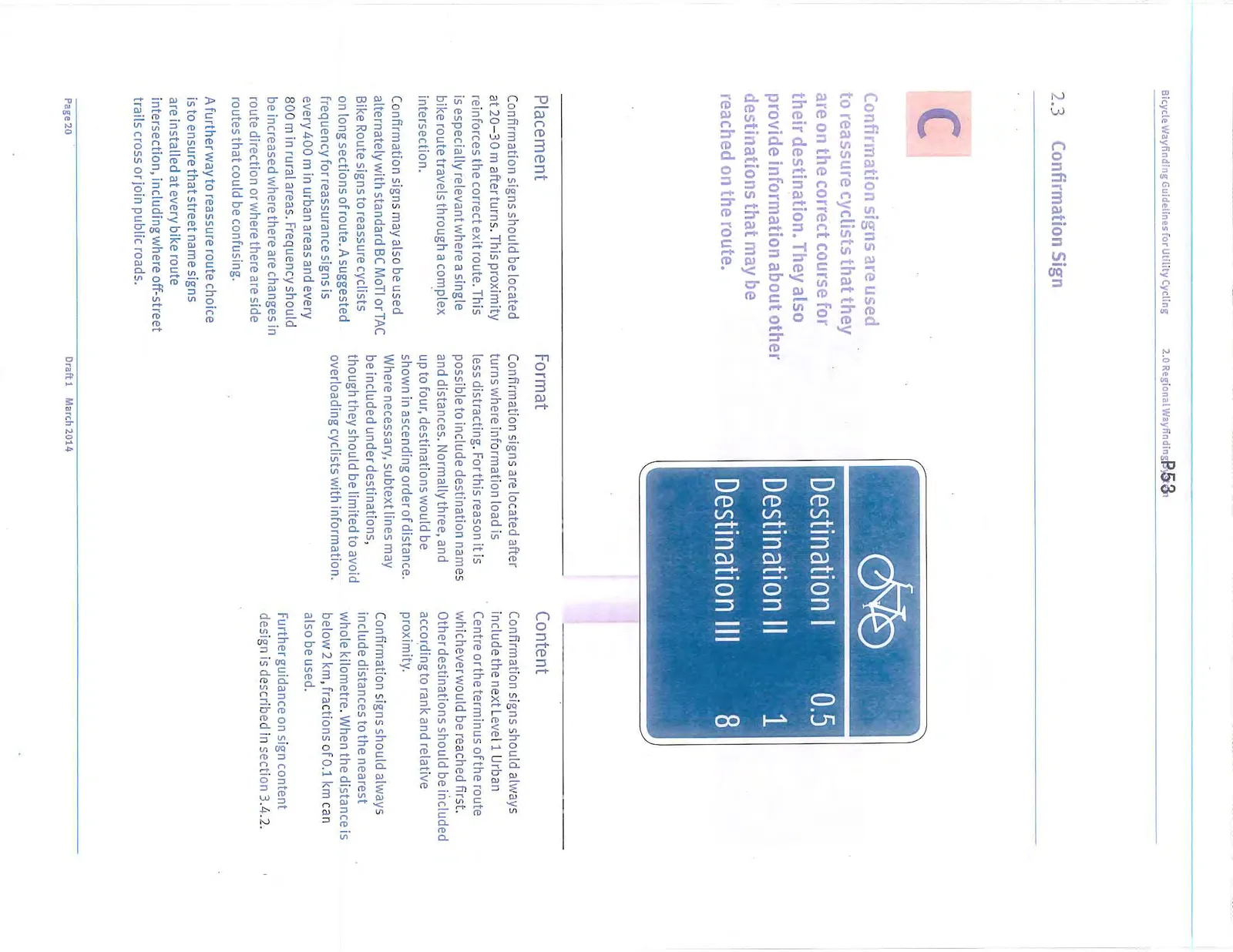
Confirmation signs are used to reassure cyclists that they are on the correct course for their destination. They also provide information about other destinations that may be reached on the route.
Placement
Confirmation signs should be located at 20–30 m after turns. This proximity reinforces the correct exit route. This is especially relevant where a single bike route travels through a complex intersection.
Confirmation signs may also be used alternately with standard BC MoTI or TAC Bike Route signs to reassure cyclists on long sections of route. A suggested frequency for reassurance signs is every 400 m in urban areas and every 800 m in rural areas. Frequency should be increased where there are changes in route direction or where there are side routes that could be confusing.
A further way to reassure route choice is to ensure that street name signs are installed at every bike route intersection, including where off-street trails cross or join public roads.
Format
Confirmation signs are located after turns where information load is less distracting. For this reason it is possible to include destination names and distances. Normally three, and up to four, destinations would be shown in ascending order of distance. Where necessary, subtext lines may be included under destinations, though they should be limited to avoid overloading cyclists with information.
Content
Confirmation signs should always include the next Level 1 Urban Centre or the terminus of the route whichever would be reached first. Other destinations should be included according to rank and relative proximity.
Confirmation signs should always include distances to the nearest whole kilometre. When the distance is below 2 km, fractions of 0.1 km can also be used.
Further guidance on sign content design is described in section 3.4.2.
2.3.1 Confirmation Sign Examples
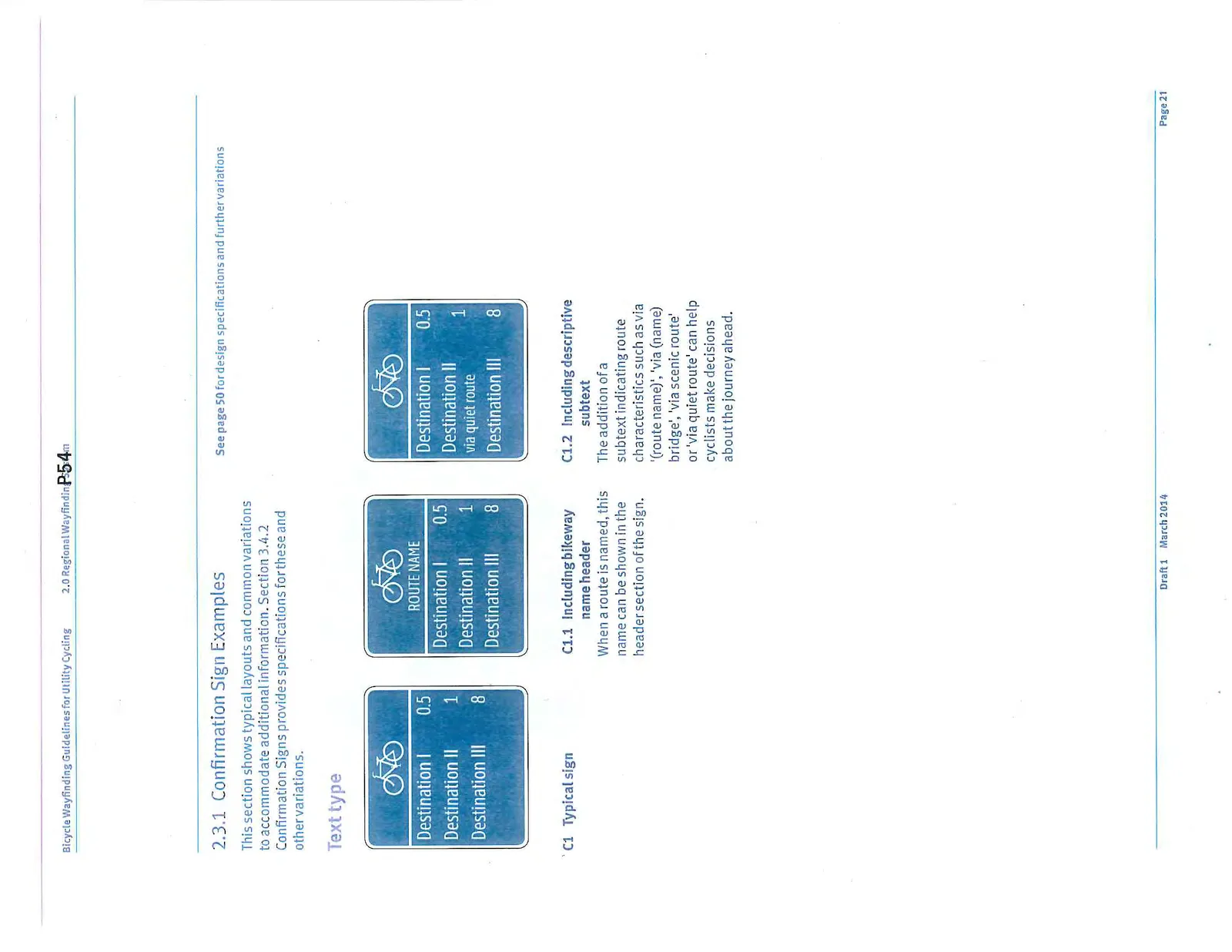
- C1 Typical sign
- C1.1 Including bikeway name header: When a route is named, this name can be shown in the header section of the sign.
- C1.2 Including descriptive subtext: The addition of a subtext indicating route characteristics such as via '(route name)', 'via (name) bridge', 'via scenic route' or 'via quiet route' can help cyclists make decisions about the journey ahead.
2.4 Turn Fingerboard
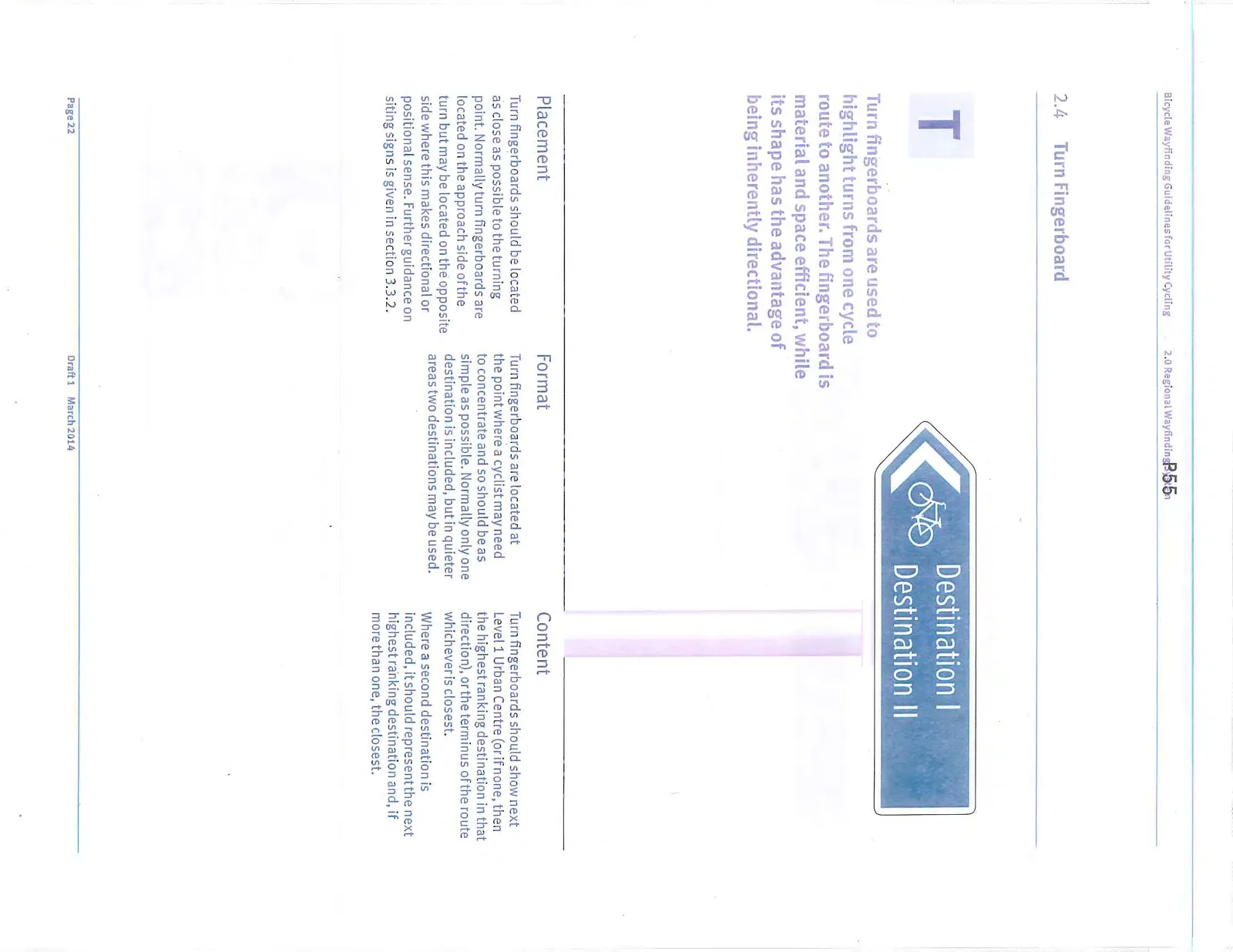
Turn fingerboards are used to highlight turns from one cycle route to another. The fingerboard is material and space efficient, while its shape has the advantage of being inherently directional.
Placement
Turn fingerboards should be located as close as possible to the turning point. Normally turn fingerboards are located on the approach side of the turn but may be located on the opposite side where this makes directional or positional sense. Further guidance on siting signs is given in section 3.3.2.
Format
Turn fingerboards are located at the point where a cyclist may need to concentrate and so should be as simple as possible. Normally only one destination is included, but in quieter areas two destinations may be used.
Content
Turn fingerboards should show next Level 1 Urban Centre (or if none, then the highest ranking destination in that direction), or the terminus of the route whichever is closest.
Where a second destination is included, it should represent the next highest ranking destination and, if more than one, the closest.
2.4.1 Turn Fingerboard Examples
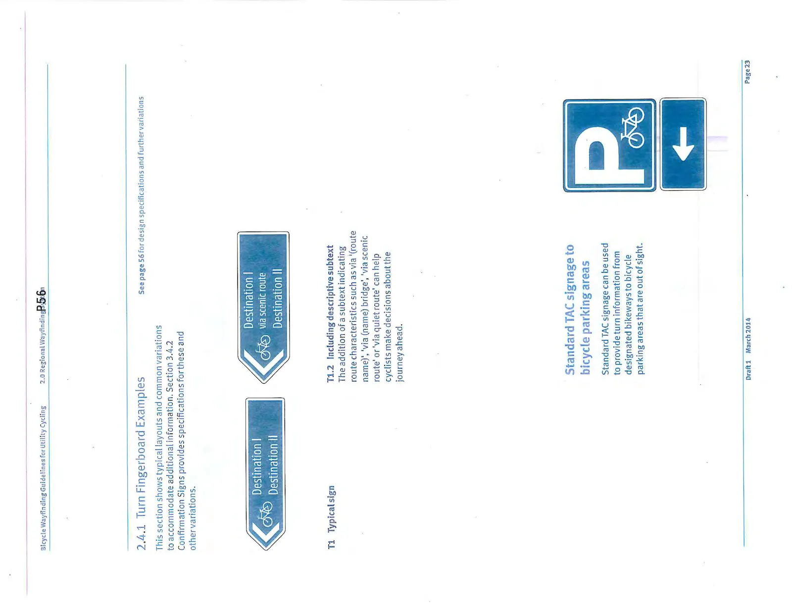
- T1 Typical sign
- T1.2 Including descriptive subtext: The addition of a subtext indicating route characteristics can help cyclists make decisions about the journey ahead.
Standard TAC signage to bicycle parking areas Standard TAC signage can be used to provide turn information from designated bikeways to bicycle parking areas that are out of sight.
2.5 Off-network Waymarker
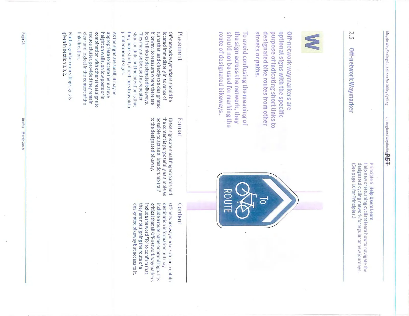
Off-network waymarkers are optional signs with the specific purpose of indicating short links to designated bike routes from other streets or paths. To avoid confusing the meaning of the sign across the network, they should not be used for marking the route of designated bikeways.
Placement
Off-network waymarkers should be located immediately in advance of turns that lead directly to a designated bikeway, to reassure where there are jogs in links to designated bikeways. They may also be used as repeater signs on links but the intention is that they mark short, direct links to avoid a proliferation of signs.
As the signs are small, it may be appropriate to locate them at eye height on walls, on low posts or in combination with other street signs to reduce clutter, provided they remain clear and logical in the context of the link direction.
Format
These signs are small fingerboards and the content is purposefully as simple as possible to act as a 'breadcrumb trail' to the designated bikeway.
Content
Off-network waymarkers do not contain destination information but may include a route name or brand logo. It is critical that all Off-network waymarkers include the word 'To' to confirm that they are not signing the route of a designated bikeway but access to it.
2.5.1 Off-network Waymarker Examples
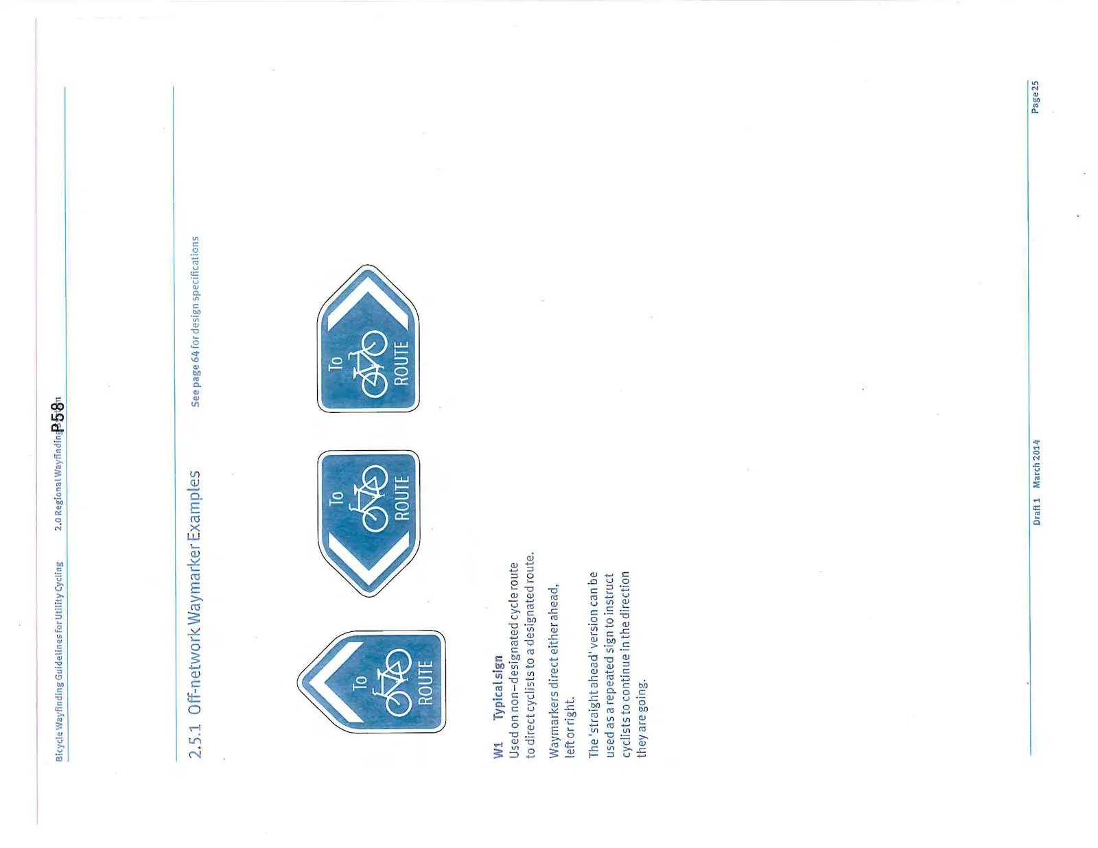
- W1 Typical sign: Used on non-designated cycle route to direct cyclists to a designated route. Waymarkers direct either ahead, left or right. The 'straight ahead' version can be used as a repeated sign to instruct cyclists to continue in the direction they are going.
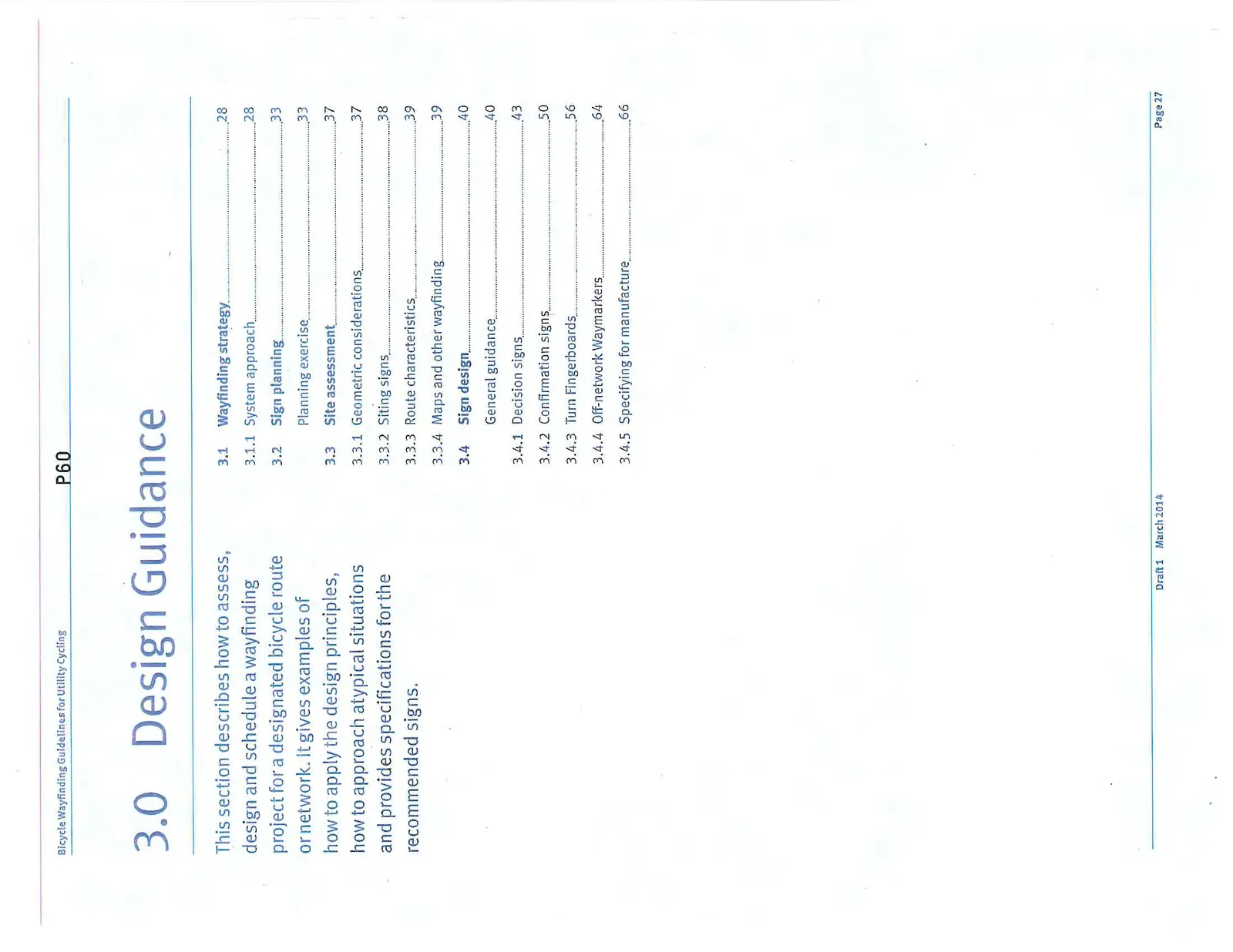
3.0 Design Guidance
This section describes how to assess, design and schedule a wayfinding project for a designated bicycle route or network. It gives examples of how to apply the design principles, how to approach atypical situations and provides specifications for the recommended signs.
3.1 Wayfinding strategy
3.1.1 System approach
The Regional Bicycle Wayfinding Guidelines are intended to promote utility trips between the principle destinations in the region using the designated bike network.
The cornerstone of the approach has been to agree on a list of destinations ranked according to trip attractiveness. This destination hierarchy is included in Section 1.4 and identifies destinations that should or may be signed.
Each authority that proposes to implement bicycle wayfinding should design signs using the same destinations and the design steps in order to ensure consistency.
Given the multiple route possibilities between destinations in the network, it is advisable to develop a wayfinding plan for the municipal or ideally, the full regional network rather than on a route-by-route basis.
The design steps are described in the following sections:
- A Consult on local destination hierarchy
- B Define a network to be signed
- C Divide the routes into segments
- D Define links to the route segments
- E Identify the decision points
- F Prepare a sign schedule
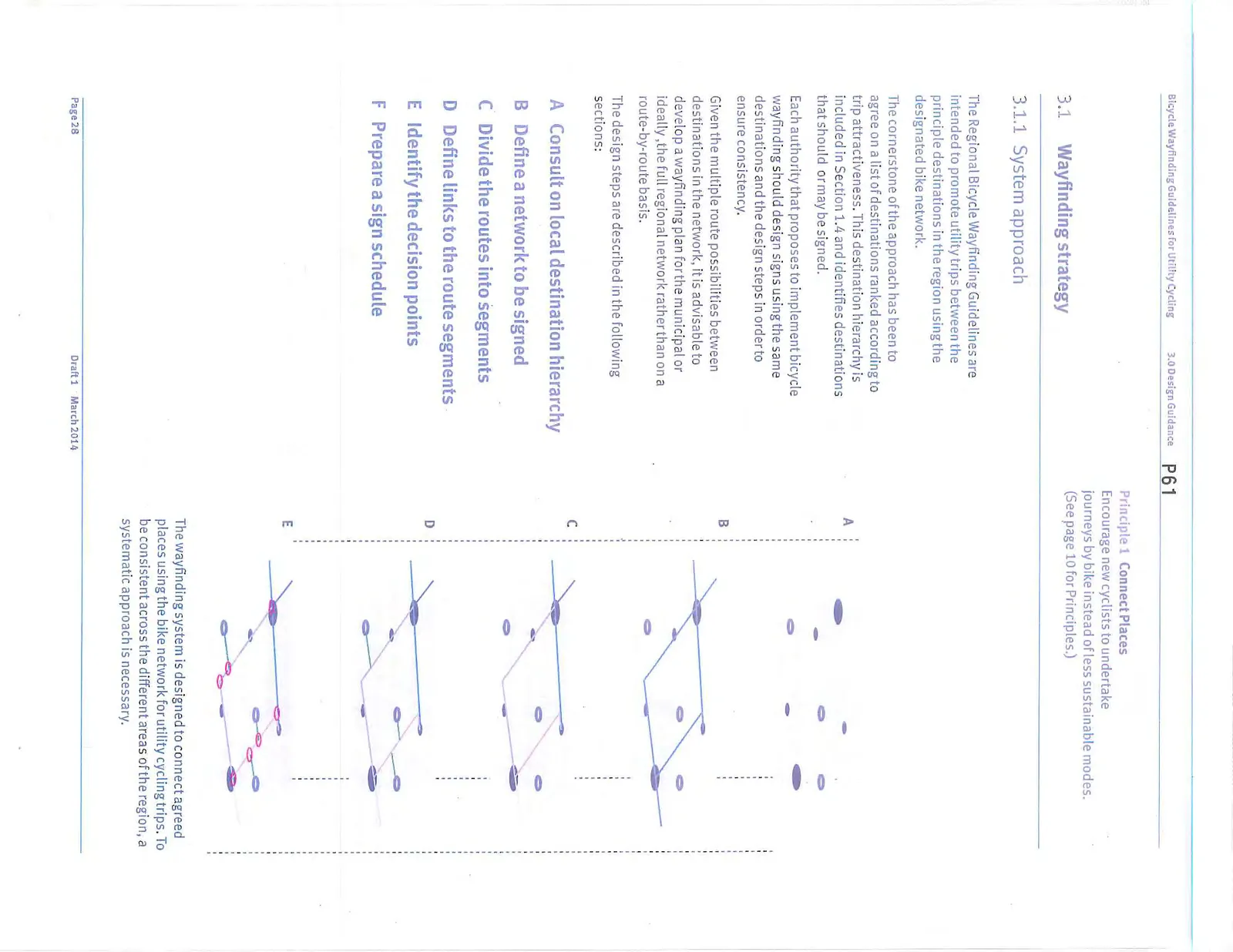
The wayfinding system is designed to connect agreed places using the bike network for utility cycling trips. To be consistent across the different areas of the region, a systematic approach is necessary.
A Local destination hierarchy
In general, regionally agreed destinations include Level 1 Urban Centres and Level 2 Local Neighbourhoods (identified through the Regional Sustainability Strategy and local Official Community Plans) as well as Level 3 Major Attractions. However provision is also made to extend this list further to include a Level 4 class of Local Destinations (see section 1.4 for advice).
Any authority wishing to include Local Destinations in their bicycle wayfinding should consider the likely need for additional signage to accommodate the extra destinations and the related need to maintain the accuracy of the information.
B Signed network
All the destinations selected in Step A should be connected by bike routes to be included in the regional wayfinding system. Routes between Level 1 Urban Centres and Level 2 Local Neighbourhoods will be the most heavily used for utility cycling and these should be identified as the primary network to be signed. As discussed above, in time this network will include the PIC.
A planning exercise, preferably as part of a local bike route plan, should establish which designated bike routes are best suited to connect the Level 1 Urban Centres and Level 2 Local Neighbourhoods. Consideration should include who will use the signs and where they may wish to ride for utilitarian purposes. The CRD’s Pedestrian and Cycling Master Plan (PCMP) includes a Bikeway Facility Classification that describes the physical route characteristics which best support utility cycling. Further consideration should be given to route connectivity beyond municipal borders and necessary municipal liaison.
This exercise will provide a network of connecting routes to be signed. It should be noted that some designated routes may be omitted if they do not connect significant trip-generating destinations while other routes may be added if they run parallel or are recreational trails that offer cyclists quieter or more scenic options.
It is also conceivable that some destinations are not yet accessible from a designated bike route. In these cases the authority should decide whether to include minimal directional signage as an Off-network Link (see Step D below), or to defer signing until a suitable route has been identified and upgraded to meet recommended designated facility standards.
C Route segments
A developed cycling network may include long routes that join several intermediate destinations. Because of this, using the route’s end points as control destinations may not be useful to most cyclists.
When preparing a content schedule, it is useful to consider long routes as a series of smaller segments, with a Level 1 or Level 2 control destination at each end of the segment. These segments are purely planning tools, and not explicitly named or presented to the public.
Each segment should start and end at a destination to produce a logical sequence for wayfinding signage. The wayfinding signage will join the segments into a series of steps for people on longer journeys.
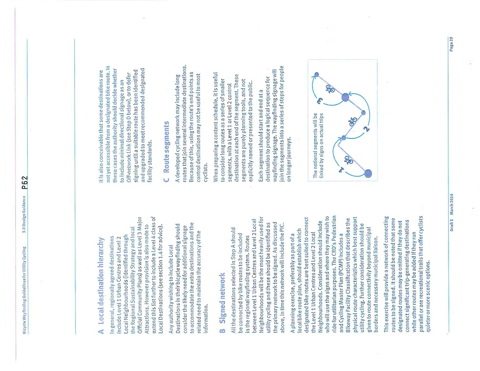
Advice for defining route segments:
- Segments should only start and end at the Level 1 and 2 destinations to ensure that wayfinding directions benefit the widest number of users.
- Segments should not start or end at Level 3 Major Attractions or Level 4 Local Destinations but may connect them if they are on the route.
- The length of each segment should ideally not exceed 8 km to match average journey distances. Where this is not practical segment lengths may be increased.
- In order of preference, segments should connect: Level 1 Urban Centres to other Urban Centres, Urban Centres to Level 2 Local Neighbourhoods and Level 2 Local Neighbourhoods to other Local Neighbourhoods.
- Where routes cross bridges, segments may end at the bridge if it is more logical that signs direct users to a municipality than a specific destination e.g. ‘Esquimalt via Johnson Street Bridge’.
- It is acceptable for parts of different segments to share a route between destinations e.g. the Trans-Canada Trail and Galloping Goose run along the same route into Downtown Victoria from different points.
D Links to segments
The route segments identified in the previous step link all the Level 1 and 2 destinations in the network, as well as any Level 3 and 4 destinations located along the way. There will likely also be some Level 3 and 4 destinations that are not on these segments, but still reachable via designated bike routes. Fewer cyclists are expected to use these routes, because they join destinations that are smaller trip attractors. These designated routes are Links between the Level 3 or 4 destination and the segments that join greater trip attractors.
Links may be signed in the same way as network segments. However, to optimize funding for greatest benefit, a municipality may choose to sign network Links as a secondary priority. In this case, a Turn Fingerboard can be included on the network Segment at the intersection with the Link, and the remainder of the Link identified with TAC Bike Route signs rather than full wayfinding signage.
After network Segments and Links have been identified, there may still be some Level 3 and 4 destinations that are not on the designated bicycle network. Generally, wayfinding signage should only occur on the designated bicycle network. For this reason, Off-network links should only be identified when the destination is relatively close to the designated network and reachable in a straight line. Signing from this destination back to the bike route may be signed using Off-network Waymarkers.
E Decision points
The preceding steps produce a map with all the agreed destinations connected by a network of segmented routes and links. At each intersection of two or more designated bikeways, a decision point is created where cyclists must choose which designated route to follow to their destination. At these intersections, full wayfinding signs are recommended.
Other types of decision points may merit different signing approaches. Where a designated route turns at an intersection, but there is no choice of an alternate designated route, standard TAC Bike route signage with an arrow tab may be sufficient.
There may also be points where a designated route intersects with the normal street network in a way that is confusing to follow. At these locations, Decision Signs and Confirmation Signs, at a minimum, should be included to assist with route-following.
F Sign schedule
The sign schedule is the last part of the planning process. The sign schedule is a list of all the directional signs needed along each route, their location, and the directions to be included on signs. The sign schedule should cover the whole route including all its component segments.
Preparing the sign schedule requires a consistent logic to be applied to the directions. Once included on a sign it is most important that a destination is signed continuously until it is reached. This can be challenging however as signs have a limited text capacity and there may be many possible destinations that could be included.
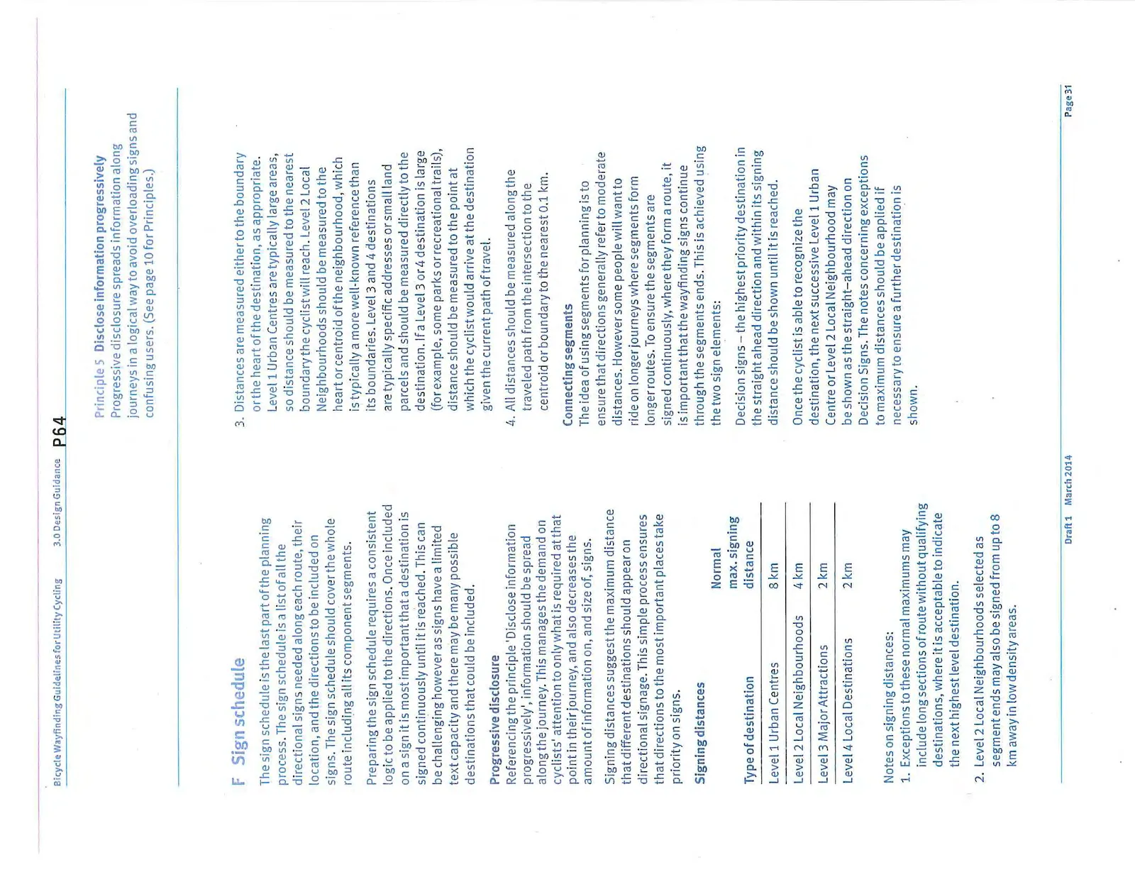
Progressive disclosure Referencing the principle ‘Disclose information progressively’, information should be spread along the journey. This manages the demand on cyclists’ attention to only what is required at that point in their journey, and also decreases the amount of information on, and size of, signs.
Signing distances suggest the maximum distance that different destinations should appear on directional signage. This simple process ensures that directions to the most important places take priority on signs.
Signing distances
| Type of destination | Normal max. signing distance |
|---|---|
| Level 1 Urban Centres | 8 km |
| Level 2 Local Neighbourhoods | 4 km |
| Level 3 Major Attractions | 2 km |
| Level 4 Local Destinations | 2 km |
Notes on signing distances:
- Exceptions to these normal maximums may include long sections of route without qualifying destinations, where it is acceptable to indicate the next highest level destination.
- Level 2 Local Neighbourhoods selected as segment ends may also be signed from up to 8 km away in low density areas.
- Distances are measured either to the boundary or the heart of the destination, as appropriate. Level 1 Urban Centres are typically large areas, so distance should be measured to the nearest boundary the cyclist will reach. Level 2 Local Neighbourhoods should be measured to the heart or centroid of the neighbourhood, which is typically a more well-known reference than its boundaries. Level 3 and 4 destinations are typically specific addresses or small land parcels and should be measured directly to the destination. If a Level 3 or 4 destination is large (for example, some parks or recreational trails), distance should be measured to the point at which the cyclist would arrive at the destination given the current path of travel.
- All distances should be measured along the traveled path from the intersection to the centroid or boundary to the nearest 0.1 km.
Connecting segments The idea of using segments for planning is to ensure that directions generally refer to moderate distances. However some people will want to ride on longer journeys where segments form longer routes. To ensure the segments are signed continuously, where they form a route, it is important that the wayfinding signs continue through the segments ends. This is achieved using the two sign elements:
Decision signs – the highest priority destination in the straight ahead direction and within its signing distance should be shown until it is reached.
Once the cyclist is able to recognize the destination, the next successive Level 1 Urban Centre or Level 2 Local Neighbourhood may be shown as the straight-ahead direction on Decision Signs. The notes concerning exceptions to maximum distances should be applied if necessary to ensure a further destination is shown.
Once the cyclist has arrived at a control destination, the next Level 1 or 2 destination that anchors the end of the next network segment should appear on subsequent Decision Signs. The exact point at which it is appropriate to stop signing to the current straight-ahead destination and change to the next one depends on what environmental cues are present to signal to the cyclist that they have arrived at the named destination.
Landmarks, neighbourhood name signs, store or street names, are some physical elements that can inform the cyclist that they have arrived at a destination, and hence a point where it is logical to begin using the next straight-ahead destination on Decision Signs.
Confirmation signs – Confirmation signs show the straight-ahead destinations in order with the nearest destination at the top. The last destination typically matches the destination on the preceding Decision Sign. Intermediate destinations should be shown within the signing distance appropriate to their level.
Sometimes the number of possible intermediate destinations may exceed the number that can fit on a single Confirmation Sign. If so, priority should be given to the highest level destinations, as they are likely to be more popular destinations, and also better known, therefore making them more useful for geographic orientation.
Named routes Route names provide a useful way to connect segments. The sign designs provide space for route names to achieve this. A number of routes across the region are already named.
Atypical decision points In some instances, wayfinding signs alone will not be adequate to guide riders through a complex decision point. Where these locations are identified in the planning stage, they should be highlighted for site assessment. Solving physically difficult decision points may require engineering or landscaping design as well as signage.
A sample sign schedule is provided on the following pages.
3.2 Sign planning
Planning exercise
The illustration shows a theoretical cycle network connecting the fictitious City of Centreville. The graphics right show a simplified sign schedule for key decision points marked W, X, Y and Z. A more detailed sign schedule may be found on page 35.
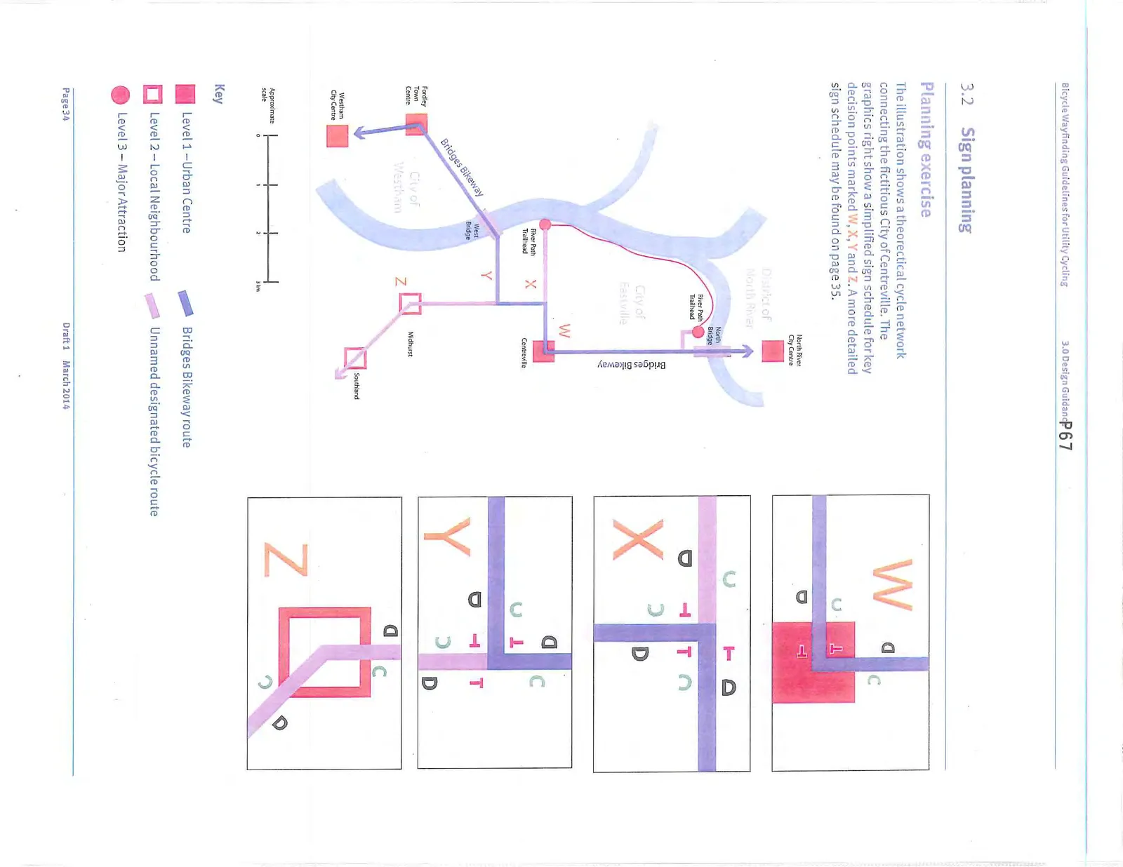
Key
- Level 1 — Urban Centre (Square)
- Level 2 — Local Neighbourhood (Hollow Square)
- Level 3 — Major Attraction (Circle)
- Bridges Bikeway route (Solid line)
- Unnamed designated bicycle route (Dashed line)
Step A Consult on local destination hierarchy The City of Centreville is planning its bicycle wayfinding. Centreville planners consult these guidelines to identify the relevant control destinations that have been agreed for the region. Centreville is a Level 1 Urban Centre while Midhurst and Southland are nearby Level 2 Local Neighbourhoods. The River Path Trail, which runs through the City, is recognized as a Level 3 Major Attraction.
Step B Define a network to be signed The designated cycling network connects the City of Centreville to the neighbouring District of North River and the Cities of Fordley and Westham via bridges. The route between the bridges through Centreville is part of a long-distance regional route called the Bridges Bikeway. Unnamed designated bicycle routes connect Southland and Midhurst to Centreville via the Bridges Bikeway. The River Path Trail is also connected to Centreville via an unnamed designated bicycle route and the Bridges Bikeway.
Step C Divide the routes into segments For signage purposes the network must be divided into notional segments with anchor destinations.
- Segment 1 connects Centreville to a bridge that leads to the District of North River. No Level 1 or Level 2 destinations are within the signing distance in North River so it is determined to be more logical to sign to the municipality.
- Segment 2 connects Centreville to the Level 1 Urban Centre Fordley via West Bridge. Fordley is within the 8 km signing distance and will be signed.
- Segment 3 connects Centreville to Southland which is a Level 2 Local Neighbourhood 6 km away. In this instance it is decided that while Southland is outside of its signing distance, the low density of the area makes it a logical segment anchor.
Step D Define links to the route segments A designated route connects each trailhead of the River Path Trail (a Level 3 Major Attraction) to the Bridges Bikeway. These routes are identified as designated route Links.
Step E Identify the decision points For the purposes of the example, four decision points are selected. These are:
- Point W – at the intersection at Centreville. All three segments connect here giving three destination choices at this point. Segment 2 and 3 run parallel to the south and southwest, requiring a decision on the southbound direction. In this case, Fordley ranks higher than Southland.
- Point X – a right angle turn on the parallel route of segment 2 and 3 and an intersection with the link to the River Path Trailhead.
- Point Y – the point where segment 2 and 3 divide before continuing to their respective destinations.
- Point Z – A turn in the local cycling route linking the Midhurst and Southland neighbourhoods.
Step F Prepare a sign schedule
Each line of the following schedule represents a separate sign. In addition to the directional signs, repeat confirmation signs or BC MoTI or TAC Bike Route signs may be required.
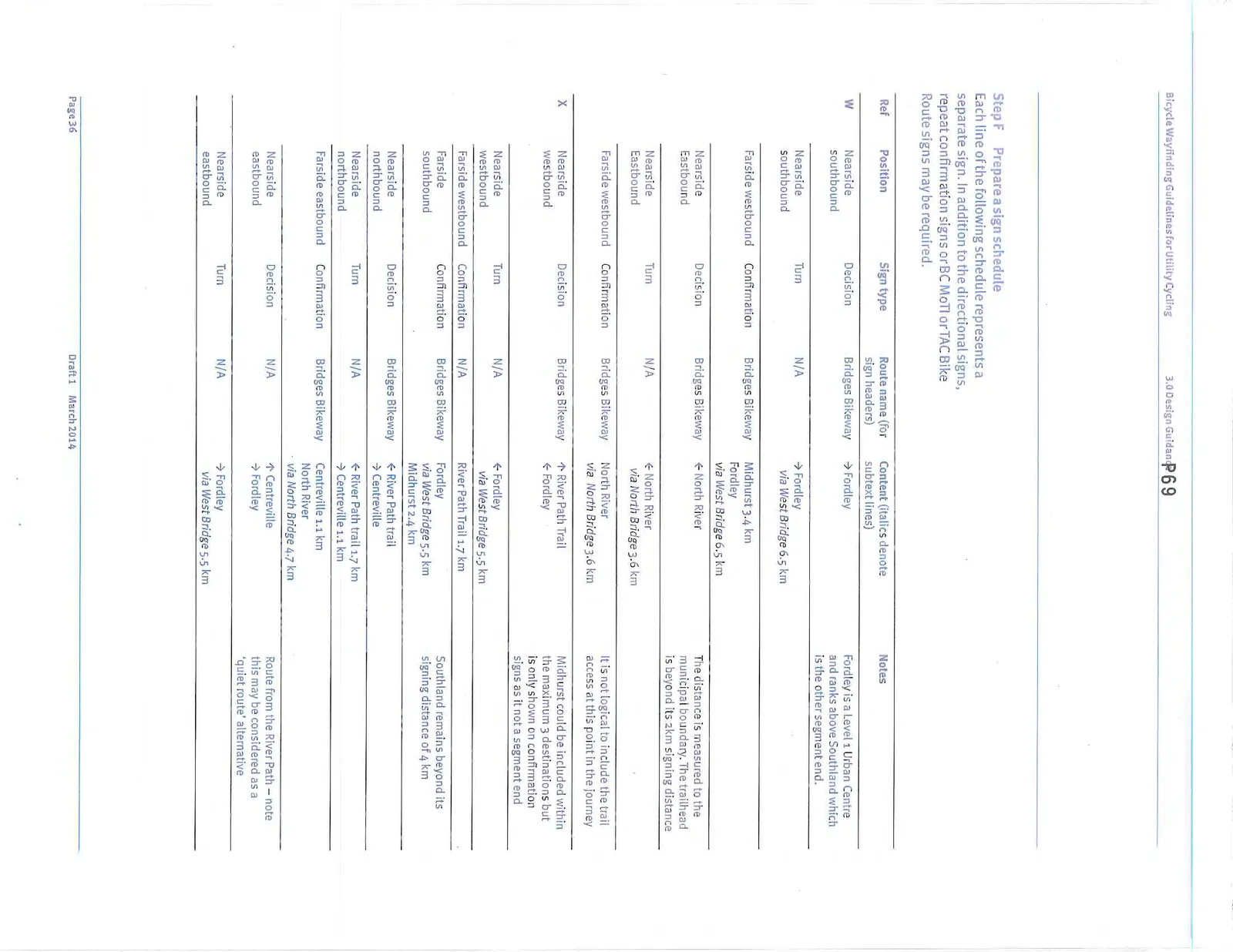
| Ref | Position | Sign type | Route name (for sign headers) | Content (italics denote subtext lines) | Notes |
|---|---|---|---|---|---|
| W | Nearside southbound | Decision | Bridges Bikeway | -> Fordley | Fordley is a Level 1 Urban Centre and ranks above Southland which is the other segment end. |
| Nearside southbound | Turn | N/A | -> Fordley via West Bridge 6.5 km | ||
| Farside westbound | Confirmation | Bridges Bikeway | Midhurst 3.4 km; Fordley via West Bridge 6.5 km | ||
| Nearside eastbound | Decision | Bridges Bikeway | <- North River | The distance is measured to the municipal boundary. The trailhead is beyond its 2km signing distance | |
| Nearside eastbound | Turn | N/A | <- North River via North Bridge 3.6 km | ||
| Farside westbound | Confirmation | Bridges Bikeway | North River via North Bridge 3.6 km | It is not logical to include the trail access at this point in the journey | |
| X | Nearside westbound | Decision | Bridges Bikeway | ^ River Path Trail; <- Fordley | Midhurst could be included within the maximum 3 destinations but is only shown on confirmation signs as it not a segment end |
| Nearside westbound | Turn | N/A | <- Fordley via West Bridge 5.5 km | ||
| Farside westbound | Confirmation | N/A | River Path Trail 1.7 km | ||
| Farside eastbound | Confirmation | Bridges Bikeway | Fordley via West Bridge 5.5 km; Midhurst 2.4 km | Southland remains beyond its signing distance of 4 km | |
| Nearside northbound | Decision | Bridges Bikeway | <- River Path Trail; -> Centreville | ||
| Nearside northbound | Turn | N/A | <- River Path Trail 1.7 km; -> Centreville 1.1 km | ||
| Farside eastbound | Confirmation | Bridges Bikeway | Centreville 1.1 km; North River via North Bridge 4.7 km | ||
| Nearside southbound | Decision | N/A | ^ Centreville; -> Fordley | Route from the River Path – note this may be considered as a 'quiet route' alternative | |
| Nearside southbound | Turn | N/A | -> Fordley via West Bridge 5.5 km |
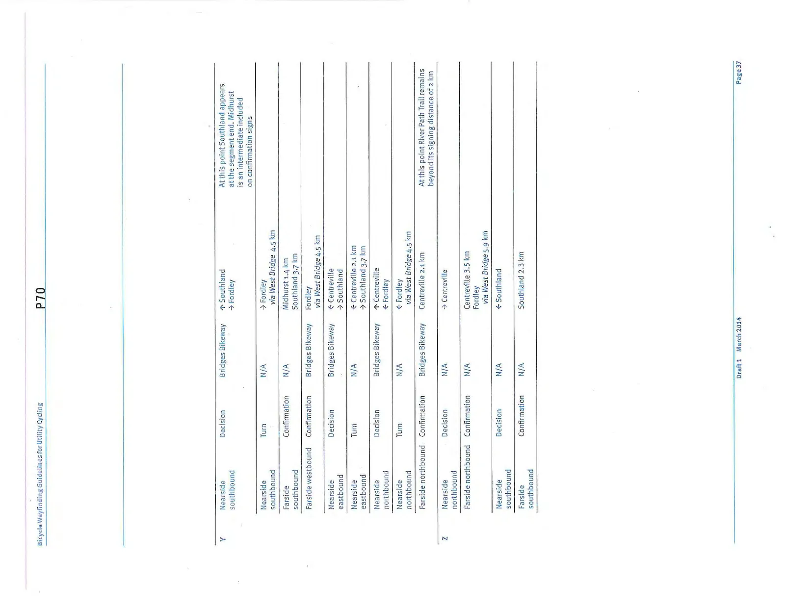
| Ref | Position | Sign type | Route name | Content (italics denote subtext lines) | Notes |
|---|---|---|---|---|---|
| Y | Nearside southbound | Decision | Bridges Bikeway | ^ Southland; -> Fordley | At this point Southland appears at the segment end. Midhurst is an intermediate included on confirmation signs |
| Nearside southbound | Turn | N/A | -> Fordley via West Bridge 4.5 km | ||
| Farside southbound | Confirmation | N/A | Midhurst 1.4 km; Southland 3.7 km | ||
| Farside westbound | Confirmation | Bridges Bikeway | Fordley via West Bridge 4.5 km | ||
| Nearside eastbound | Decision | Bridges Bikeway | <- Centreville; -> Southland | ||
| Nearside eastbound | Turn | N/A | <- Centreville 2.1 km; -> Southland 3.7 km | ||
| Nearside northbound | Decision | Bridges Bikeway | ^ Centreville; <- Fordley | ||
| Nearside northbound | Turn | N/A | <- Fordley via West Bridge 4.5 km | ||
| Farside northbound | Confirmation | Bridges Bikeway | Centreville 2.1 km | At this point River Path Trail remains beyond its signing distance of 2 km | |
| Z | Nearside northbound | Decision | N/A | -> Centreville | |
| Farside northbound | Confirmation | N/A | Centreville 3.5 km; Fordley via West Bridge 5.9 km | ||
| Nearside southbound | Decision | N/A | <- Southland | ||
| Farside southbound | Confirmation | N/A | Southland 2.3 km |
3.3 Site assessment
Introduction
The preceding section describes the planning process to determine a sign schedule suitable for site assessment. Site assessment is invaluable as it allows the designer to evaluate conditions, determine exact sign locations, and to identify any specific wayfinding challenges.
It is recommended that, where possible, site assessments are made by bicycle to give a representative perspective of the issues.
3.3.1 Geometric considerations
The site assessment is an opportunity to review geometric design considerations that relate to wayfinding including:
- Should a bike box for a two-stage "hook" left turn be considered?
- Are sight lines acceptable?
- Are on-road to off-road transitions clear?
For geometric design guidance please refer to:
- The Transportation Association of Canada's Geometric Design Guide for Canadian Roads and Bikeway Traffic Control Guidelines for Canada provides guidance concerning the design of facilities.
- National Association of City Transportation Officials (NACTO) Urban Bikeway Design Guide also includes additional information especially on Two stage Turn Queue boxes (Bike boxes for left turns).
3.3.2 Siting signs
Placement recommendations based on TAC and MoTI guidance are provided below. However, engineering judgment and a review of the existing site conditions should also be used on a case-by-case basis to determine the specific placement of each sign.
Decision signs
Deciding the distance of a decision sign from a turn or transition will be affected by design speed, site lines and slope. Decision signs should be placed along the right-of-way in places where the cyclist can see an upcoming sign from an appropriate distance given the design speed and physical context. For guidance, see TAC Bikeway Traffic Control Guidelines for Canada for minimum stopping sight distances for cyclists.
Signs should be placed further from the intersection on busier streets with a centre turn lane or left turn pocket to decrease the possibility of conflicting cyclist/motorist movements while preparing for a left turn. The location of the sign should exceed the stopping distance needed by the fastest expected travel speed, but should not be placed so far in advance that the relevance of the sign is lost or forgotten.
Confirmation signs
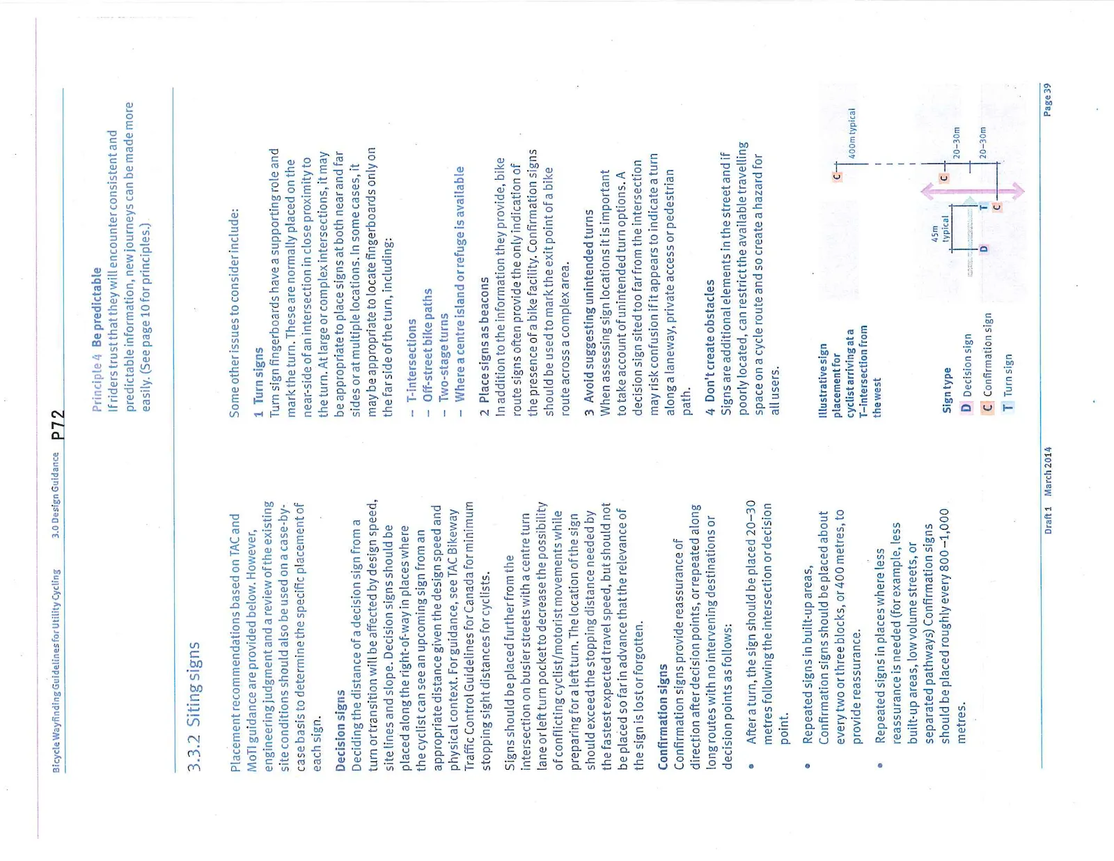
Confirmation signs provide reassurance of direction after decision points, or repeated along long routes with no intervening destinations or decision points as follows:
- After a turn, the sign should be placed 20–30 metres following the intersection or decision point.
- Repeated signs in built-up areas. Confirmation signs should be placed about every two or three blocks, or 400 metres, to provide reassurance.
- Repeated signs in places where less reassurance is needed (for example, less built-up areas, low volume streets, or separated pathways) Confirmation signs should be placed roughly every 800–1,000 metres.
Principle 4 Be predictable
If riders trust that they will encounter consistent and predictable information, new journeys can be made more easily. (See page 10 for principles.)
Some other issues to consider include:
1 Turn signs Turn sign fingerboards have a supporting role and mark the turn. These are normally placed on the near-side of an intersection in close proximity to the turn. At large or complex intersections, it may be appropriate to place signs at both near and far sides or at multiple locations. In some cases, it may be appropriate to locate fingerboards only on the far side of the turn, including:
- T-intersections
- Off-street bike paths
- Two-stage turns
- Where a centre island or refuge is available
2 Place signs as beacons In addition to the information they provide, bike route signs often provide the only indication of the presence of a bike facility. Confirmation signs should be used to mark the exit point of a bike route across a complex area.
3 Avoid suggesting unintended turns When assessing sign locations it is important to take account of unintended turn options. A decision sign sited too far from the intersection may risk confusion if it appears to indicate a turn along a laneway, private access or pedestrian path.
4 Don't create obstacles Signs are additional elements in the street and if poorly located, can restrict the available travelling space on a cycle route and so create a hazard for all users.
3.3.3 Route characteristics
A site assessment should always note changes in route character, surface condition or traffic speed and volume. Cyclists often select routes according to a range of factors including directness, suitability of the surface to the user's bicycle, personal risk threshold and physical effort.
Where route conditions change along its length a cyclist may look for alternative routes.
If possible, it is helpful to consider providing signage for alternative routes where:
- Paved routes become unpaved routes, or
- Quieter routes join much busier or faster moving traffic, or
- Routes climb steep hills.
3.3.4 Maps and other wayfinding
Some locations may function as important nodes on the cycling network and be places where additional information such as maps, interpretive, transit information or route diagrams may be welcomed.
Good candidates for such nodes include:
Transit facilities Train stations, ferry ports or bus exchanges will often lie on or close to designated bike routes. Linking bike journeys with transport is an essential component of bicycle accessibility in many areas of the region.
Trailheads In some areas, designated bike routes join trails and recreational paths. These provide access for recreational cycling and can be of regional or local importance as leisure or sporting attractions.
3.4 Sign design
General guidance
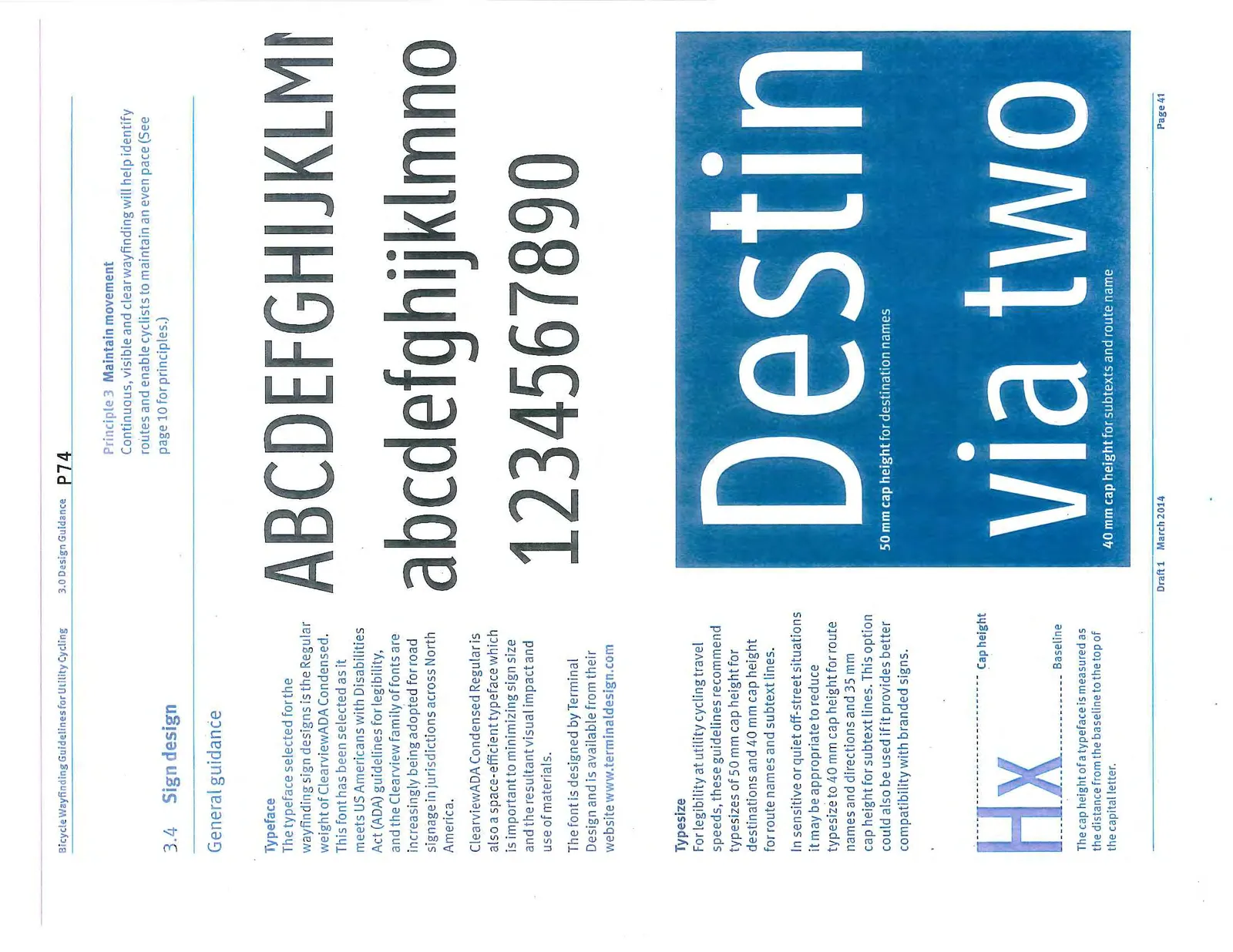
Typeface The typeface selected for the wayfinding sign designs is the Regular weight of ClearviewADA Condensed. This font has been selected as it meets US Americans with Disabilities Act (ADA) guidelines for legibility, and the Clearview family of fonts are increasingly being adopted for road signage in jurisdictions across North America.
ClearviewADA Condensed Regular is also a space-efficient typeface which is important to minimizing sign size and the resultant visual impact and use of materials.
The font is designed by Terminal Design and is available from their website www.terminaldesign.com
Typesize For legibility at utility cycling travel speeds, these guidelines recommend typesizes of 50 mm cap height for destinations and 40 mm cap height for route names and subtext lines.
In sensitive or quiet off-street situations it may be appropriate to reduce typesize to 40 mm cap height for route names and directions and 35 mm cap height for subtext lines. This option could also be used if it provides better compatibility with branded signs.
The cap height of a typeface is measured as the distance from the baseline to the top of the capital letter.
Principle 3 Maintain movement
Continuous, visible and clear wayfinding will help identify routes and enable cyclists to maintain an even pace (See page 10 for principles.)
Sign sizes
A consideration in the design of the system is optimizing sign sizes in order that they are manageable and affordable to produce but large enough to convey the information clearly.
All signs have standard sizes which will provide a sign large enough to show typical information.
Turn fingerboards and Off-network Waymarker sizes are demonstrated in the design specifications on the following pages.
Decision and Confirmation signs conform to the standards set out by TAC. Hence the standard width of Decision and Confirmation signs is fixed at 600 mm. Sign heights are however changeable subject to the required content.
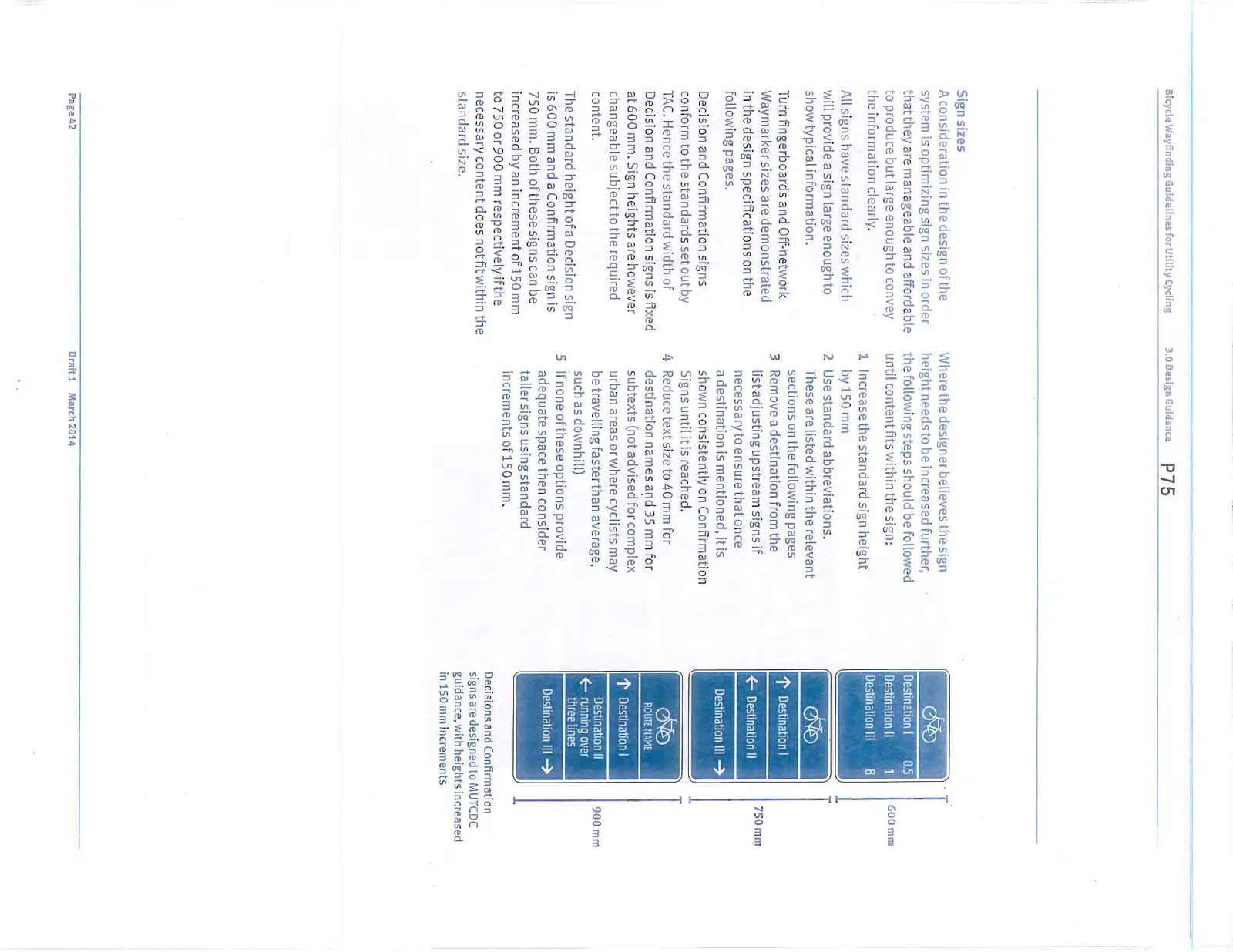
The standard height of a Decision sign is 600 mm and a Confirmation sign is 750 mm. Both of these signs can be increased by an increment of 150 mm to 750 or 900 mm respectively if the necessary content does not fit within the standard size.
Where the designer believes the sign height needs to be increased further, the following steps should be followed until content fits within the sign:
- Increase the standard sign height by 150 mm
- Use standard abbreviations. These are listed within the relevant sections on the following pages
- Remove a destination from the list adjusting upstream signs if necessary to ensure that once a destination is mentioned, it is shown consistently on Confirmation Signs until it is reached.
- Reduce text size to 40 mm for destination names and 35 mm for subtexts (not advised for complex urban areas or where cyclists may be travelling faster than average, such as downhill)
- If none of these options provide adequate space then consider taller signs using standard increments of 150 mm.
Municipal branding Where necessary, a potential option for adding municipal identity to bicycle wayfinding is the addition of a branded sign plate above the sign panel to display municipal branding.
Alternatives might include alternate locations on the pole, a vinyl decal or finial.
Note: This is for illustration only and not part of the CRD bicycle wayfinding standards. The CRD logo has been used as a placeholder for municipal identity in the above example.
3.4.1 Decision signs
Standard dimensions
Panel size 600 x 750 mm
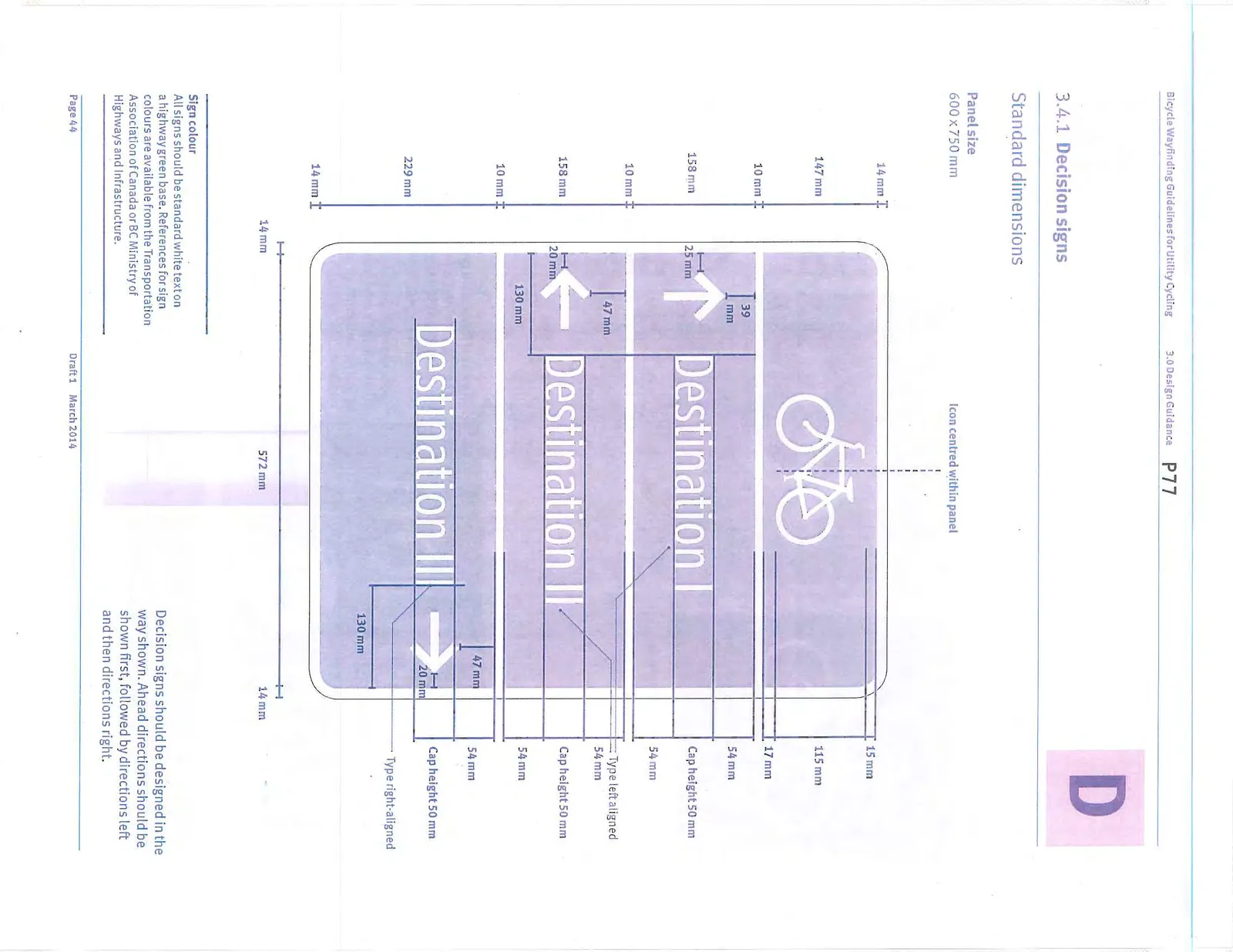
Sign colour All signs should be standard white text on a highway green base. References for sign colours are available from the Transportation Association of Canada or BC Ministry of Highways and Infrastructure.
Decision signs should be designed in the way shown. Ahead directions should be shown first, followed by directions left and then directions right.
Standard elements
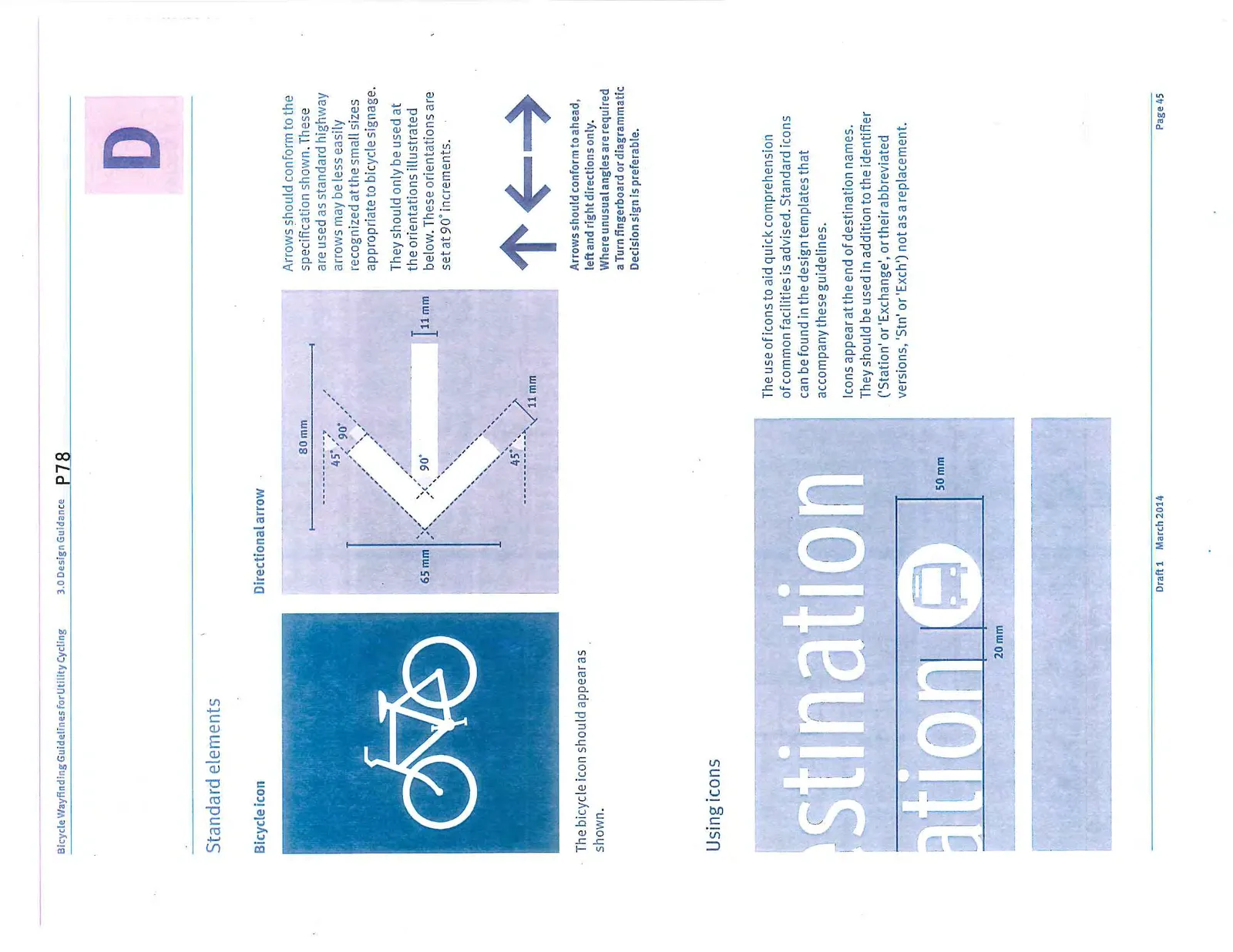
Bicycle icon The bicycle icon should appear as shown.
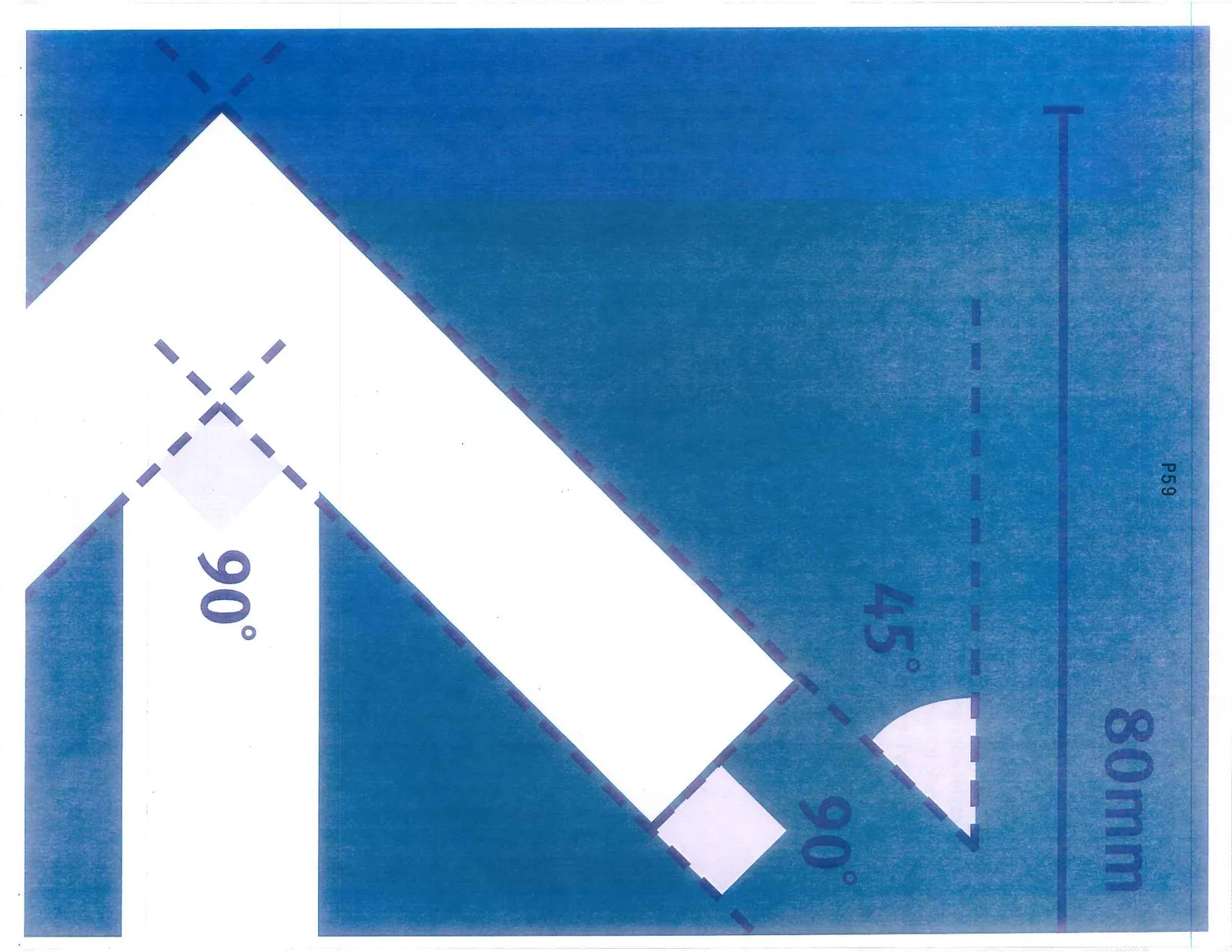
Directional arrow Arrows should conform to the specification shown. These are used as standard highway arrows may be less easily recognized at the small sizes appropriate to bicycle signage. They should only be used at the orientations illustrated below. These orientations are set at 90° increments.
Using icons The use of icons to aid quick comprehension of common facilities is advised. Standard icons can be found in the design templates that accompany these guidelines. Icons appear at the end of destination names. They should be used in addition to the identifier (‘Station’ or ‘Exchange’, or their abbreviated versions, ‘Stn’ or ‘Exch’) not as a replacement.
Adding a route name
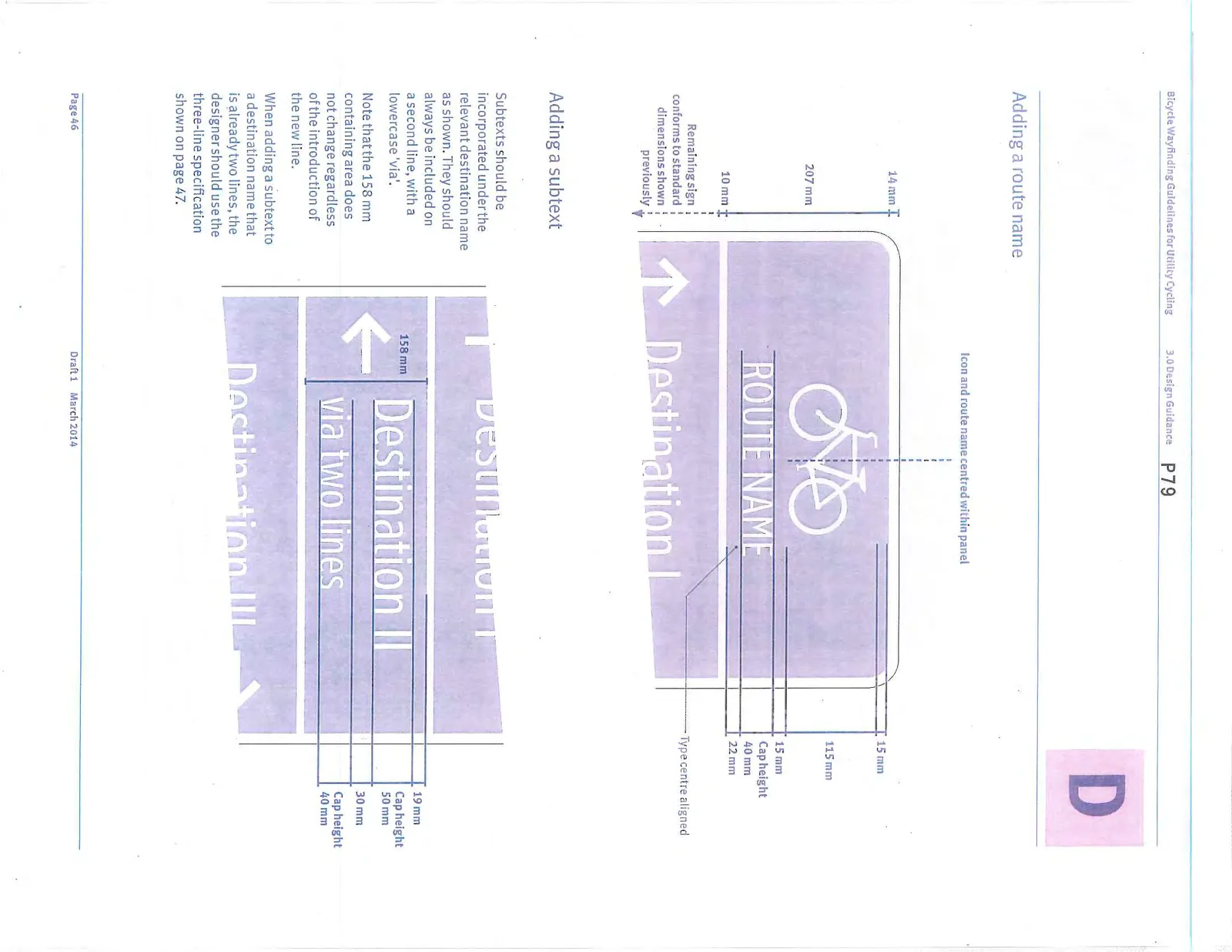
Adding a subtext
Subtexts should be incorporated under the relevant destination name as shown. They should always be included on a second line, with a lowercase ‘via’. Note that the 158 mm containing area does not change regardless of the introduction of the new line. When adding a subtext to a destination name that is already two lines, the designer should use the three-line specification shown on page 47.
Destination names that run to two lines
Longer destination names may require two lines. This should be done as shown. Again, the 158 mm containing area does not change regardless of the introduction of the new line.
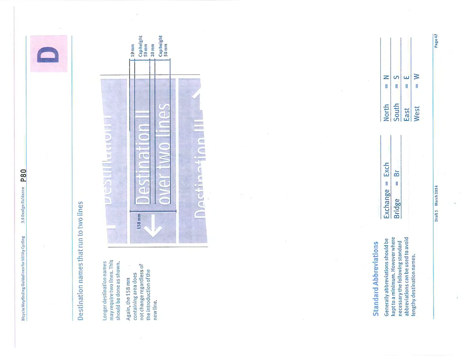
Standard Abbreviations
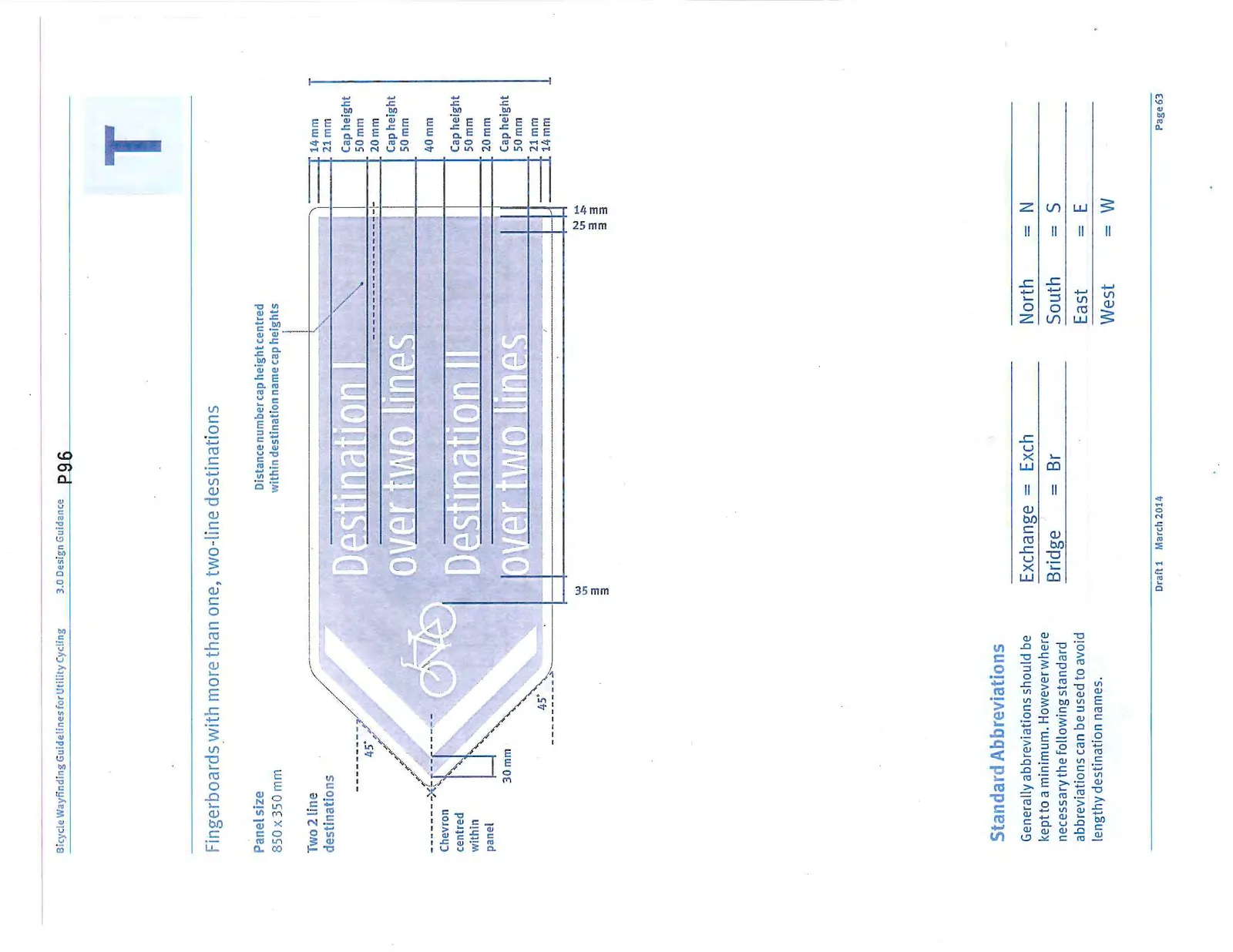
Generally abbreviations should be kept to a minimum. However where necessary the following standard abbreviations can be used to avoid lengthy destination names.
| Full word | Abbreviation | Full word | Abbreviation | |
|---|---|---|---|---|
| Exchange | Exch | North | N | |
| Bridge | Br | South | S | |
| East | E | |||
| West | W |
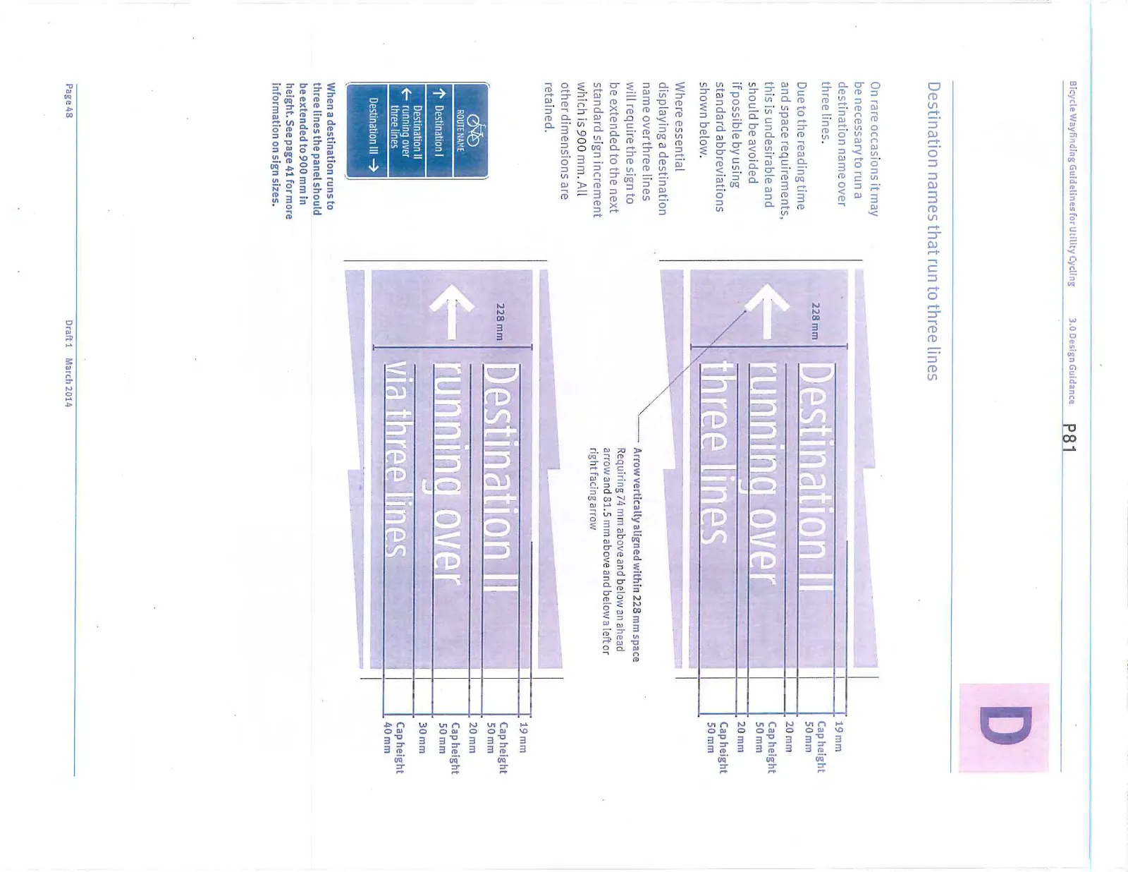
Destination names that run to three lines
On rare occasions it may be necessary to run a destination name over three lines. Due to the reading time and space requirements, this is undesirable and should be avoided if possible by using standard abbreviations shown below. Where essential displaying a destination name over three lines will require the sign to be extended to the next standard sign increment which is 900 mm. All other dimensions are retained.
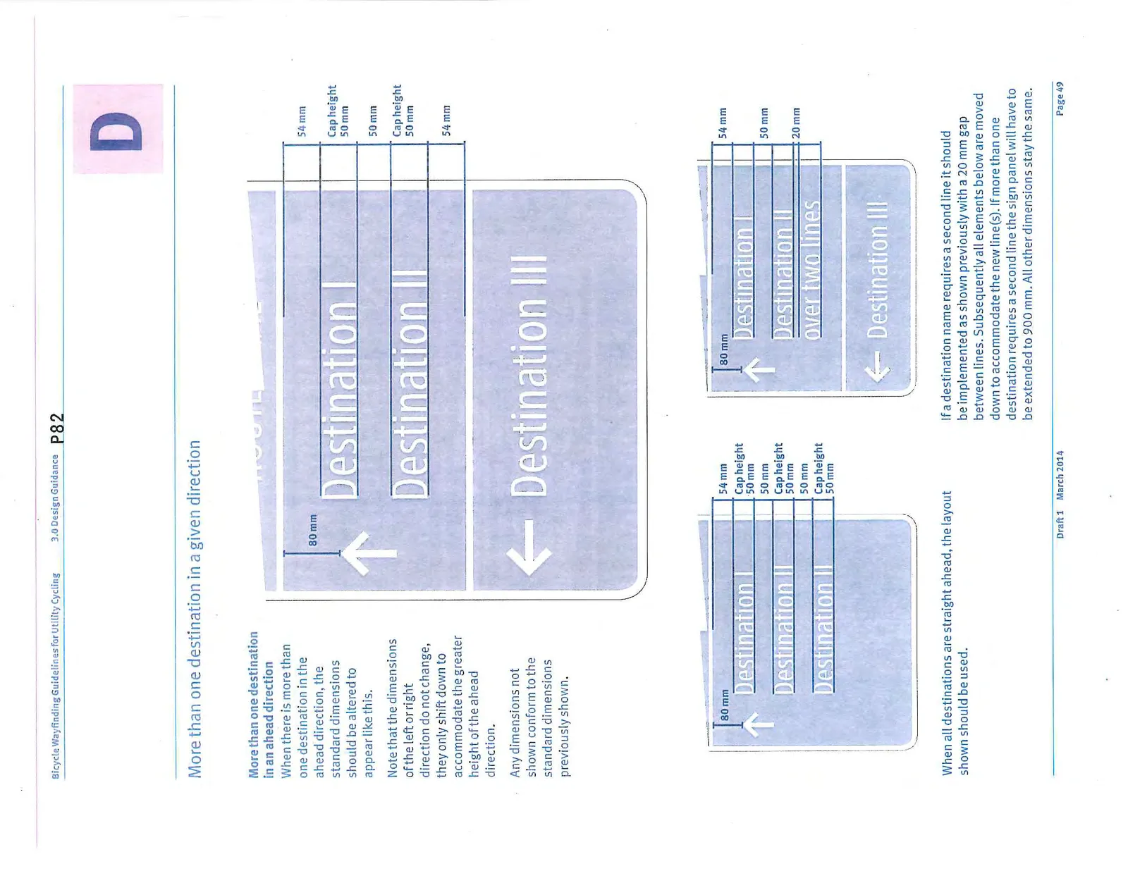
More than one destination in a given direction
When there is more than one destination in the ahead direction, the standard dimensions should be altered to appear like this. Note that the dimensions of the left or right direction do not change, they only shift down to accommodate the greater height of the ahead direction.
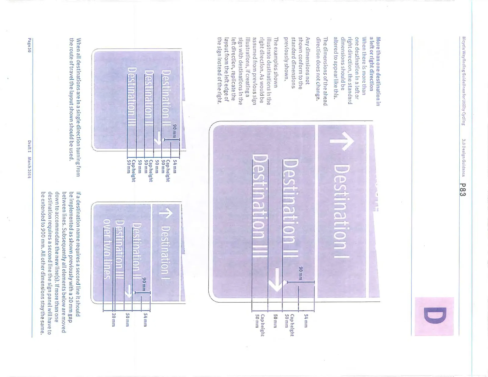
More than one destination in a left or right direction
When there is more than one destination in a left or right direction, the standard dimensions should be altered to appear like this. The dimensions of the ahead direction does not change.
3.4.2 Confirmation signs
Standard dimensions
Panel size 600 x 600 mm
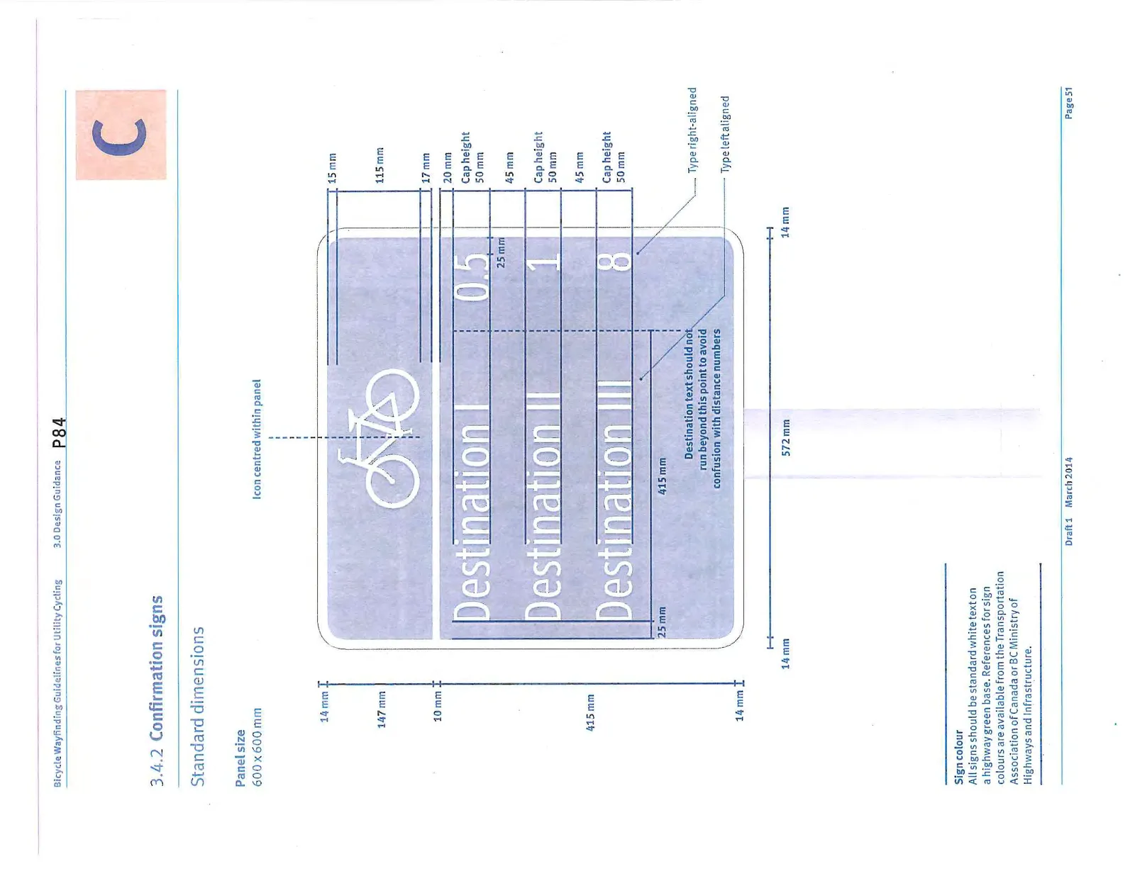
Sign colour All signs should be standard white text on a highway green base.
Standard elements
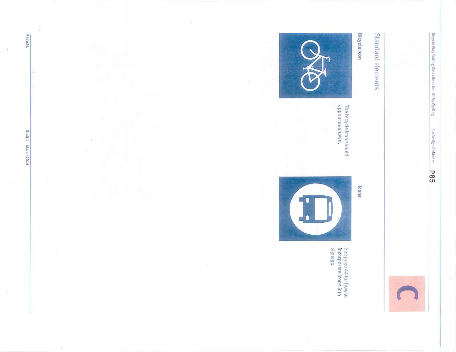
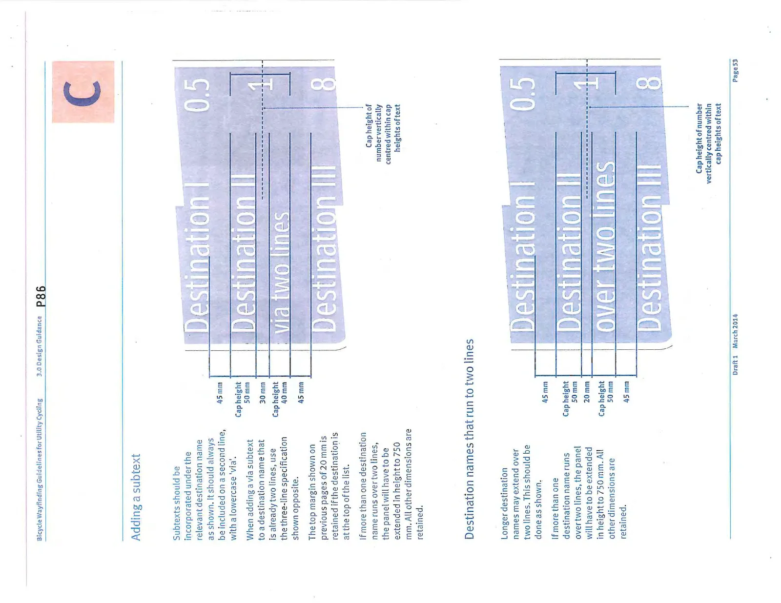
Adding a subtext
Subtexts should be incorporated under the relevant destination name as shown. It should always be included on a second line, with a lowercase 'via'. The top margin shown on previous pages of 20 mm is retained if the destination is at the top of the list. If more than one destination name runs over two lines, the panel will have to be extended in height to 750 mm. All other dimensions are retained.
Destination names that run to two lines
Longer destination names may extend over two lines. This should be done as shown.
Destination names that run to three lines
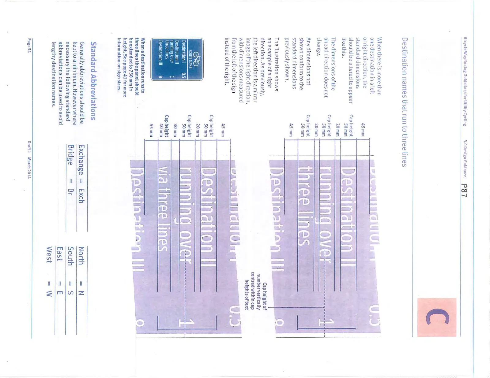
Standard Abbreviations
Generally abbreviations should be kept to a minimum. However where necessary standard abbreviations can be used to avoid lengthy destination names. (Same table as Decision signs).
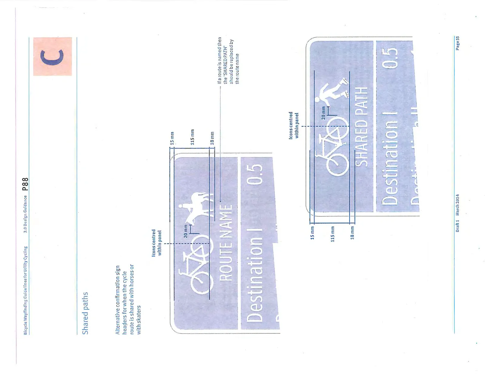
Shared paths
Alternative confirmation sign headers for when the cycle route is shared with horses or with skaters.
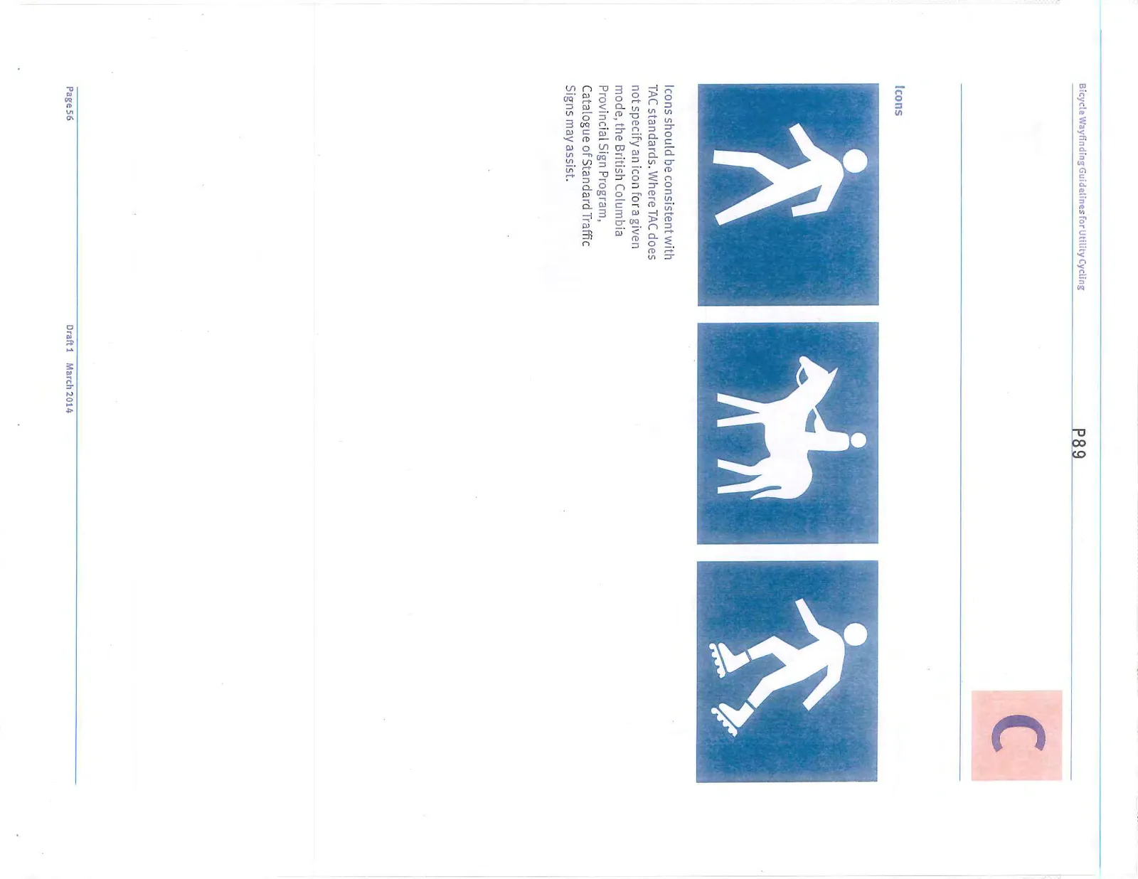
Icons
3.4.3 Turn Fingerboards
Standard dimensions
Panel size 850 x 215 mm
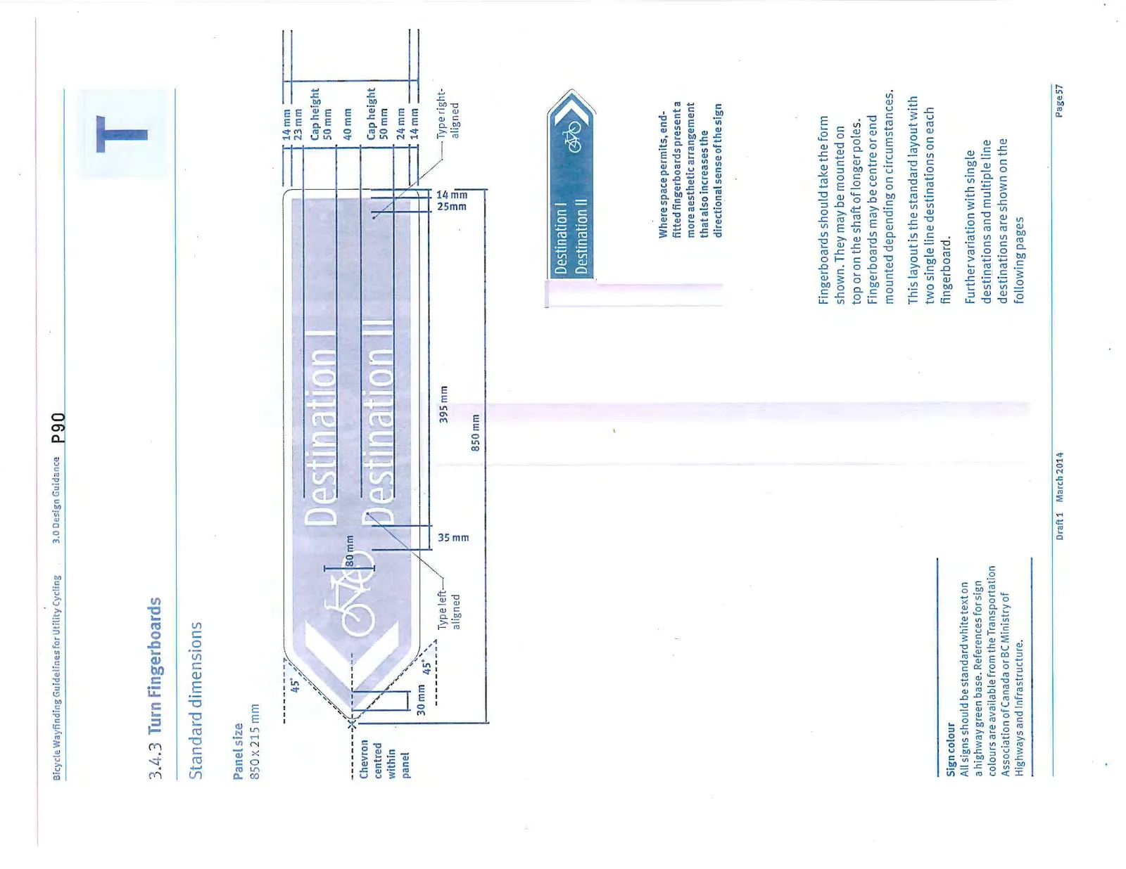
Sign colour All signs should be standard white text on a highway green base.
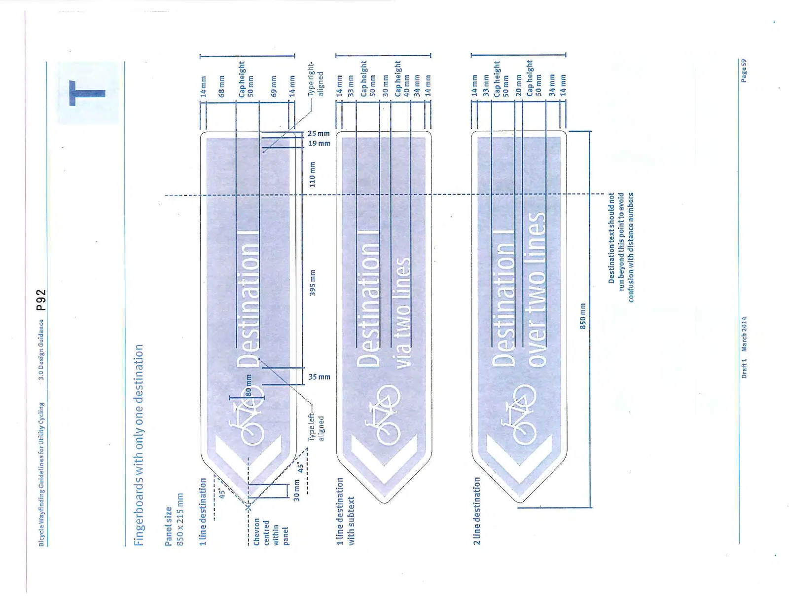
Fingerboards should take the form shown. They may be mounted on top or on the shaft of longer poles. Fingerboards may be centre or end mounted depending on circumstances. This layout is the standard layout with two single line destinations on each fingerboard. Further variation with single destinations and multiple line destinations are shown on the following pages.
Standard elements
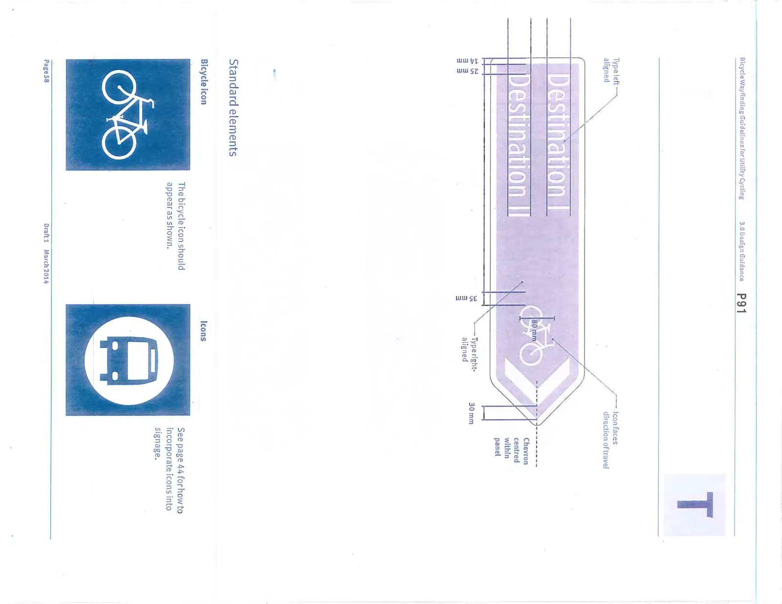
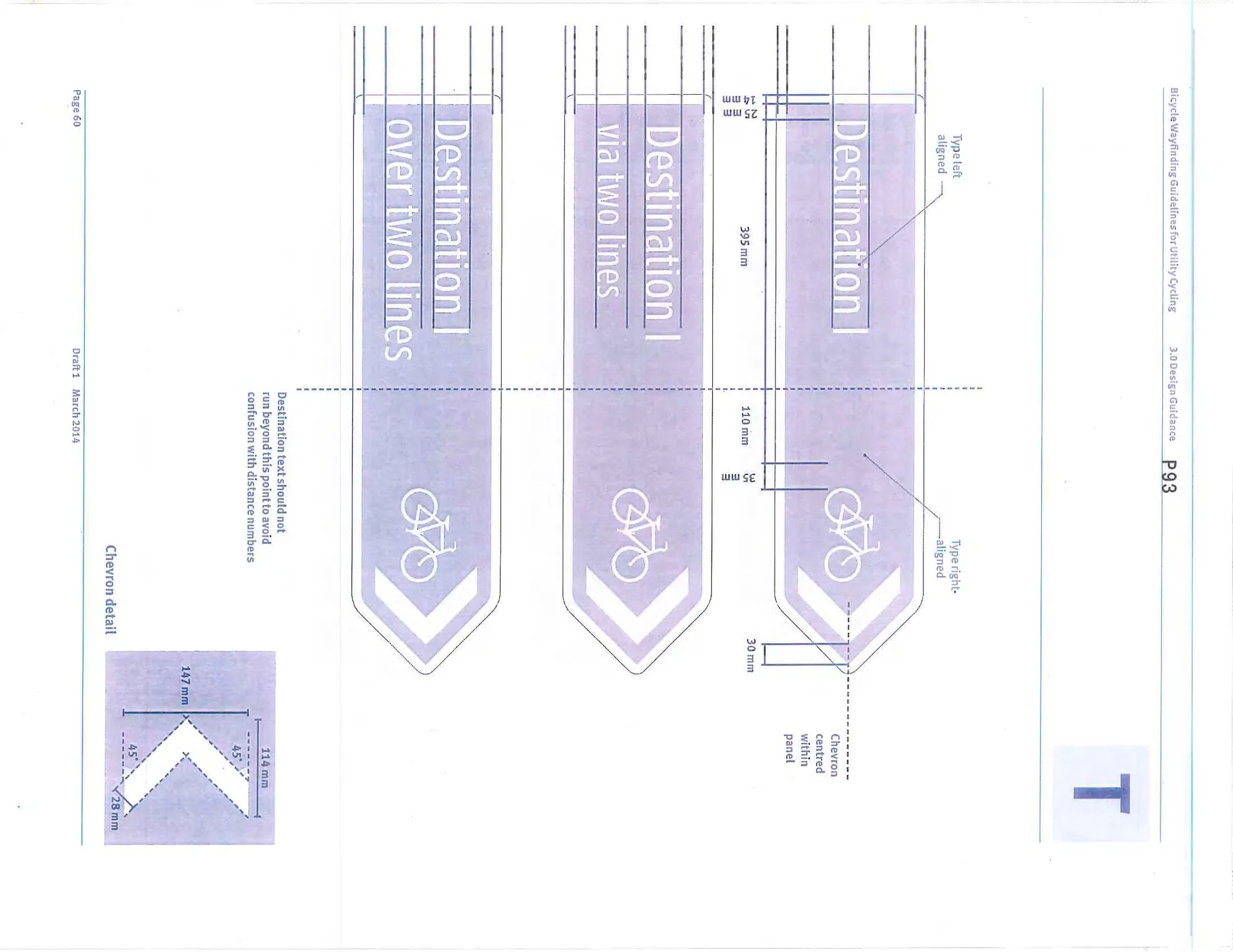
Fingerboards with only one destination
Panel size 850 x 215 mm
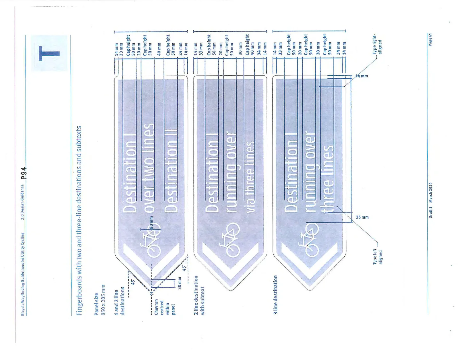
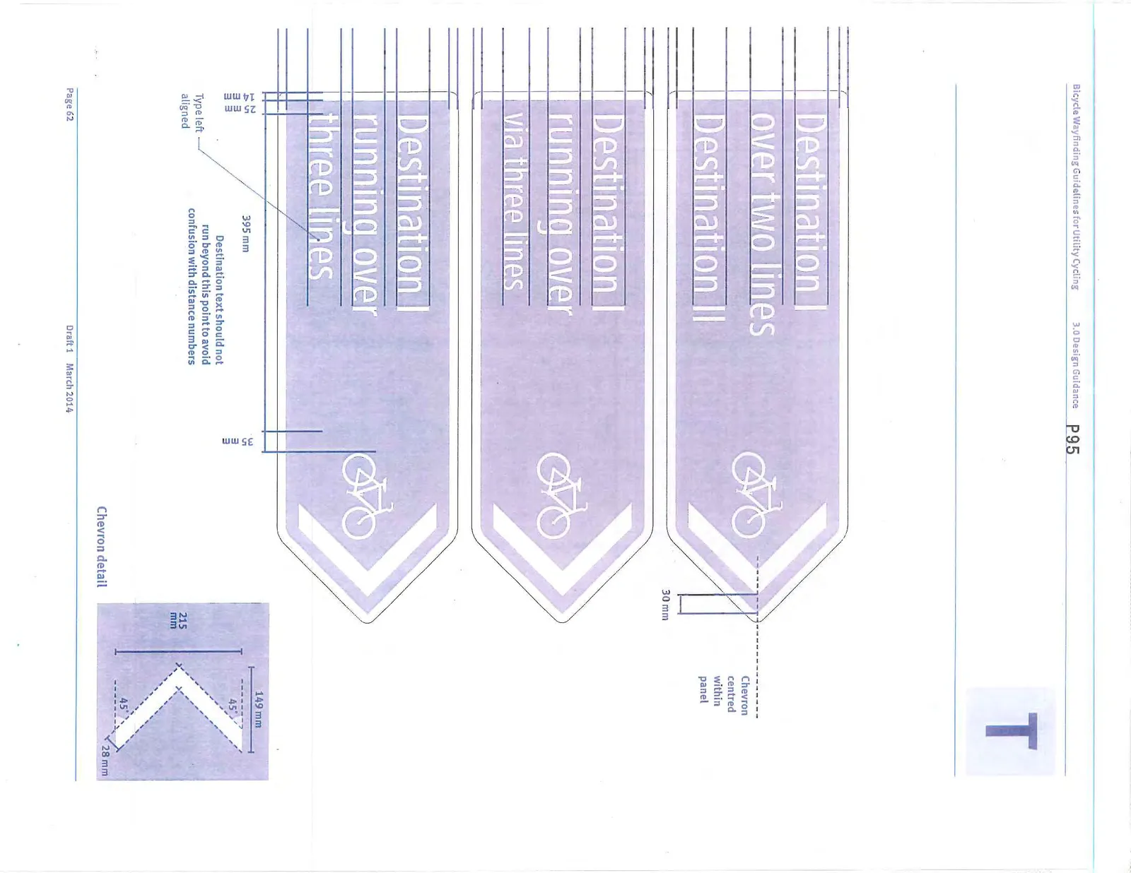
Fingerboards with two and three-line destinations and subtexts
Panel size 850 x 285 mm
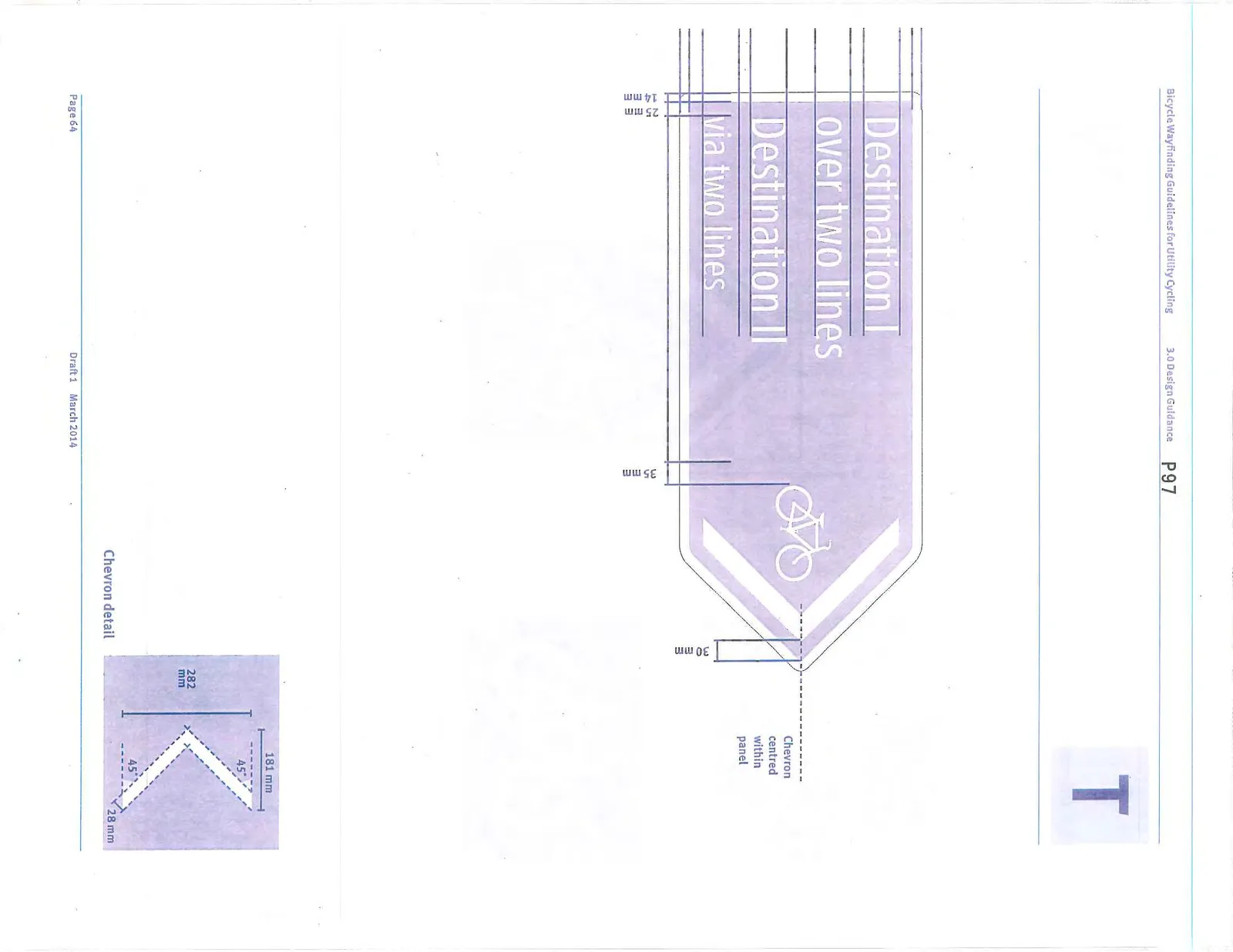
Fingerboards with more than one, two-line destinations
Panel size 850 x 350 mm
3.4.4 Off-network Waymarkers
Standard dimensions
Panel size 300 x 450 mm
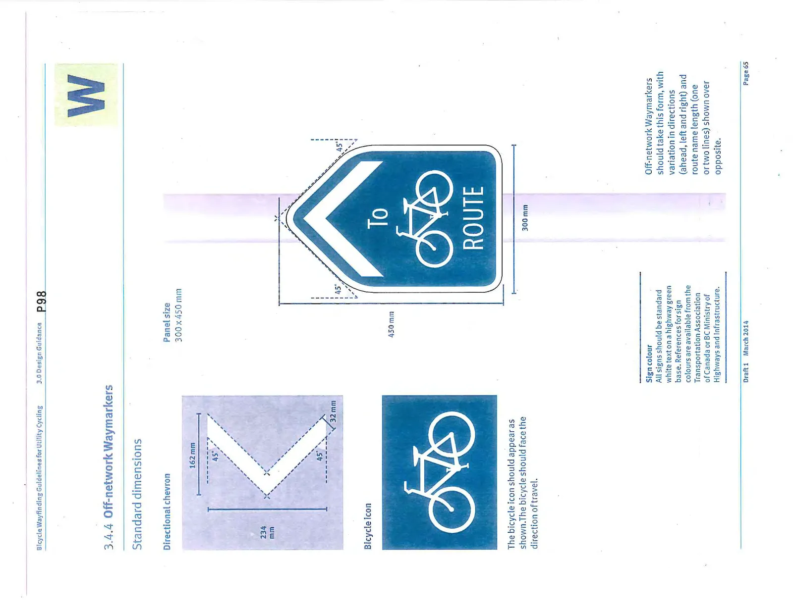
Sign colour All signs should be standard white text on a highway green base.
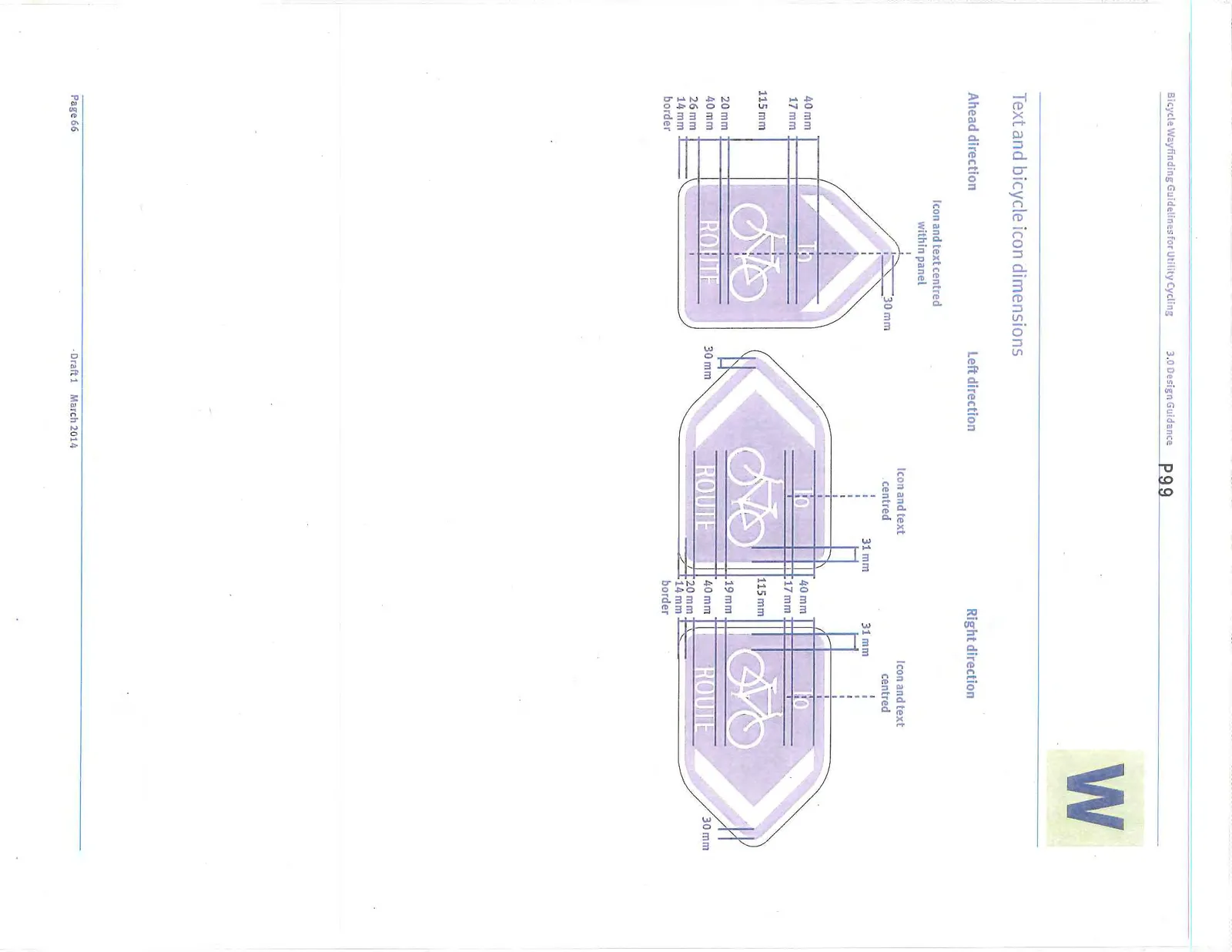
Off-network Waymarkers should take this form, with variation in directions (ahead, left and right) and route name length (one or two lines) shown over opposite.
Text and bicycle icon dimensions
3.4.5 Specifying for manufacture
CRD municipalities determine their own standards for signage products. Specifications for materials, reflectivity, mounting and installation methods should be added to the agreed sign schedule in a manner appropriate to the application and relevant local, provincial and national sign production standards.
Appendix 1
Intersection example To follow
Document Images
(16)