Engineering Drawings - Becker Residence (Sheets S1-S10)
Comprehensive set of structural engineering drawings for the residence at 12 Vickery Road.
DRAWING LIST
| Drawing No. | Description | Revision | Date |
|---|---|---|---|
| S0 | Cover sheet | revised for foundation | 2020.02.14 |
| S1 | General notes & standard concrete details | revised for foundation | 2020.02.14 |
| S2 | General notes & standard details | revised for foundation | 2020.02.14 |
| S3 | General notes & standard details | revised for foundation | 2020.02.14 |
| S4 | Foundation plan | revised for foundation | 2020.02.14 |
| S5 | Upper floor framing plan | revised for foundation | 2020.02.14 |
| S6 | Roof framing plan | revised for foundation | 2020.02.14 |
| S7 | Concrete sections | revised for foundation | 2020.02.14 |
| S8 | Details | revised for foundation | 2020.02.14 |
| S9 | Framing details | revised for foundation | 2020.02.14 |
| S10 | Framing details | revised for foundation | 2020.02.14 |

Becker residence 12 Vickery Road, View Royal, BC Project No: 10441
S1 - General Notes & Standard Concrete Details
GENERAL NOTES
- Construction shall comply with all applicable codes and industry standards as noted in the contract documents. The consulting structural engineer assumes no responsibility for the consequences of failure by builders to obtain necessary approvals from the authority having jurisdiction.
- The contractor shall review all contract documents in conjunction with other disciplines and shall verify all dimensions and review documentation for discrepancies. Contact the engineer and design team for clarification prior to construction. All unreported discrepancies are the responsibility of the contractor.
- All structural design is limited to the structural components shown on these drawings. Design of components not clearly identified on these drawings is to be supplied by those supplier of these components. If design values and loads for these components differ from the parameters shown on these drawings, if there is any ambiguity, consult the structural engineer.
- The structure is designed to resist the design loads once completed. All bracing and support necessary for stability during construction is the responsibility of the contractor.
- Use only drawings that have been prepared specifically for construction and are labeled as such.
- Detail marker represented as [Detail Number] / [Sheet Number] shall be read as detail #1 on page S6.
- See architectural drawings for floor and roof elevations and sections, recesses, drainage slopes, etc.
- The following notes in the various sub-categories of general notes are to be followed unless noted otherwise. If unclear, consult with the engineer.
DESIGN DATA
- All structural components in this drawing package have been designed in accordance with the following codes: a. BCBC 2018
- Climatic data used for the design of these structural components: Location: View Royal, BC Ss = 1.3 kPa, Sr = 0.3 kPa Wind: q50 = 0.4 kPa Seismic: Sa(0.2) = 1.32, Sa(0.5) = 1.19, Sa(1.0) = 0.697, Sa(2.0) = 0.415, Sa(5.0) = 0.122, PGA = 0.609, Site Class = D
- All foundations are designed in accordance with limit states design. Soil bearing capacity is assumed to be as follows: Serviceability Bearing Capacity (SLS) = 100 kPa Ultimate Bearing Capacity (ULS) = 125 kPa
FOUNDATIONS
- All concrete for foundations is to be as per the supplier's specifications to meet the following requirements in accordance with CSA 23.1/23.2 and CSA 23.3: a. minimum 28-day compressive strength f'c = 25 MPa b. exterior foundation walls and footings to meet class F-2 performance c. interior foundation walls, footings and slabs to meet class N performance
- Foundations to be placed in cast with tolerances not to exceed the following: a. footing width: -1" to +2" b. footing depth: -1/2" to +1/2" c. wall thickness: ± 1/4" d. concrete clear cover: ± 1/4" e. footing misplacement or eccentricity is allowable up to 2% of footing width in direction of misplacement but shall not exceed 2".
- The tolerances provided in notes 2 and 3 do not relieve the contractor of his or her responsibility of meeting more rigid requirements specified elsewhere in the construction documents or as required by equipment shop drawings or specifications such as those for elevators, etc.
- Footings to be placed on a suitable substrate with the specified frost protection, refer to plan.
- It is the contractor's responsibility to verify that the soil conditions are suitable for the foundations as per design by engaging a suitably qualified individual to confirm the soil bearing capacity and usefulness.
- Protection of adjacent structures is the responsibility of the contractor.
- All foundations to be located as per these structural drawings. Where specific notes aren't provided, the foundations are to be centered under the support from above.
- Footings are designed in accordance with limit states design. Service confirm bearing pressure prior to placing footings as footings may need to be lowered to suit site services.
- Dowels are to be placed prior to concrete pour unless approval to do otherwise has been obtained from Simpson. Templates should be used to set column or holddown anchorage.
- All foundation walls are to be continuous from footing to floor system above.
- Provide two (2) 15M continuous at top of all foundation walls.
- Provide minimum 2x3 keyway in all footings unless poured monolithically with walls.
- Provide minimum two 15M continuous through footings.
- Unless specified otherwise, provide 15M @ 18" o/c each way at bottom of pad footings.


CONCRETE
- All concrete is to meet the following requirements in accordance with CSA 23.1/23.2 and CSA 23.3: a. minimum 28-day compressive strength f'c = 25 MPa, U.N.O.
- The contractor is responsible for concrete that meets the performance requirements stated above.
- Concrete to have architectural or concrete finishes as specified by the design drawings and is to be the responsibility of the contractor.
- Provide the following minimum concrete clear covers U.N.O.: a. Footings placed against soil: 75mm (3") b. Placed beside normal, free draining soil or fill: 38mm (1-1/2") c. Against soil with sulfides, chlorides or sulfates: 65mm (2-1/2") d. Slabs-on-grade: 20mm (3/4") e. Minimum Clear Cover U.N.O.: 32mm (1-1/4")
- All slabs to have 6x6-10/10 welded wire fabric (WWF) reinforcement at mid-depth of slab (U.N.O.). All slabs to have 10M bars @ 18" o/c each way or as per BCBC 2018 (6.6.7.1/4.2.1.4.1) welded wire mesh in the slab, centered (not on the ground) unless noted otherwise. Mesh must be located between 1/3 and 2/3 depth of slab.
- Continuous footings shall have reinforcement with a minimum lap distance of 600mm (24"). At reentrant corners rebar is to extend 600mm beyond corner, U.N.O.
- All openings in slabs 24" (600mm) or larger to have two 15M bars extending 600mm beyond corners.
- Slab reinforcing shall not be spliced at doorway or other openings, U.N.O.
- Slabs on grade are not to bear on foundation walls.
- Concrete to have a minimum yield strength of 300 MPa for 10M bars and 400 MPa for all larger bar with a minimum lap distance as per CSA 23.3 and CSA S269.1.
- Splice length of rebar to be a minimum of 600 mm (24") U.N.O.
- Rebar fabrication and installation shall be in accordance with CSA A23.1 to verify compressive strength and failure mode at 7 and 28 days.
- Provide a sampling of concrete field testing in accordance with CSA A23.1 to verify compressive strength and failure mode at 7 and 28 days.
- It is recommended to provide saw cut control joints at 10' intervals to control cracking. Control joints may be replaced with construction joints where required. Crack control is the responsibility of the contractor.
S2 - General Notes & Standard Details
RETAINING WALLS
- Retaining walls are defined as any concrete wall retaining grade that is not supported at the top by a floor or roof system.
- All concrete for retaining walls is to have a minimum 28-day compressive strength of f'c = 25 MPa.
- Weep holes should be included or perforated drain pipes be installed to provide appropriate drainage. See below.
- Backfill to be designed by geotechnical engineer.
- See architectural drawings and elevations for wall locations and heights.
- Vertical reinforcing in retaining walls shall always be located on the high grade side.
| height (H) | B | T1 | T2 | "C" bar | "D" bar | "E" bar |
|---|---|---|---|---|---|---|
| between 4'-6' | 3'-0" | 8" | 10" | 15M @ 16" | 15M @ 16" | 15M @ 20" |
| between 6'-8' | 4'-0" | 8" | 10" | 15M @ 12" | 15M @ 10" | 15M @ 18" |
| between 8'-10' | 5'-0" | 10" | 12" | 15M @ 12" | 15M @ 8" | 15M @ 16" |
ROUGH CARPENTRY
- All wood framing is to conform with CSA O86.
- Wire nails, spikes and staples are to be fabricated in accordance with CSA 111.1.
- Framing lumber is to be SPF #2 or better U.N.O.
- Wall sheathing is to be oriented strand board (OSB) to CAN3-O437.0 grade 0-2.
- All floors and roofs are considered to be diaphragms and must be built with the following framing: a. All floor sheathing is to be 3/4" plywood glued and nailed to framing. b. Perimeter nailing of sheets to be 2-1/2" nails at 6" o/c. c. Intermediate nailing of sheets to be 2-1/2" nails at 12" o/c. d. All roof sheathing is to be 1/2" plywood nailed to framing. e. Perimeter nailing of sheets to be 2-1/2" nails at 6" o/c. f. Intermediate nailing of sheets to be 2-1/2" nails at 12" o/c. g. Sheathing could be replaced with 5/16" OSB provided there is a minimum of 2x decking to support the gravity loads.
- T&G decking is permitted to act as a diaphragm in lieu of sheathing if it is oriented at 45° to the framing.
- U.N.O. walls are considered to provide lateral restraint and are constructed with: a. 1/2" OSB sheathing or better. b. 2-1/2" nails at 6" o/c around perimeter of each panel. c. 2-1/2" nails at 12" o/c for intermediate panel framing. d. 2x6 studs at 16" o/c for foundation walls up to floor/roof framing. e. If studs are placed 24" o/c use 5/8" plywood. f. Provide double top plates on all load bearing walls, and splice top plates with a minimum of 12-3" nails at each side of the splice.
- Provide a suitable post base connector and cap connector for all free standing posts. Verify suitability of connector with Engineer before installation.
- Block all edges of sheathing above openings.
- Birdsmouths in joists are not to exceed noted size or 1/4 of depth of member.
- All posts are to be continuous with blocking in floor systems or posts below to match post right down to the foundation. Larger posts may be specified at lower levels.
- Provide double bottom plates for all walls on floors with concrete topping.
- All sills or plates resting on concrete or masonry shall be pressure treated SPF or other approved chemically treated lumber.
- Lumber joists over 15' 0" long should have blocking or bridging at 1/3 and 2/3 spans.
- Provide minimum 1-1/2" bearing for framing members unless noted otherwise.
- Provide full width joists under beams, U.N.O.
- Provide blocking between trusses and nail roof diaphragm to blocking.
- Any damaged OSB may be substituted for plywood.
- Provide blocking at midpoint support between joists where suitable.
- Acceptable deflection limits used in the structural design process are as follows: a. Roof Framing: i. Snow Load: L/360 ii. Total Load: L/240 b. Floor Framing: i. Live Load: L/480 ii. Total Load: L/240
SHEARWALLS
- Shearwalls to be constructed in accordance with CSA O86.
- A continuous load path is required between the shearwalls and the foundation.
- Chords at edges of shearwall to be two ply minimum, U.N.O., complete with holddown connection.
- Plywood panel dimensions not to be less than 2400 mm x 1200 mm (8 ft x 4 ft), except near boundaries, openings and changes in framing where up to two short panels, with panel dimensions not less than 300 mm may be used.
- For panels that are applied directly to framing as exterior siding, the minimum panel thickness shall be 9.5mm.
- Panel edges backed with 38 mm or wider framing. Panels are installed either horizontally or vertically. Fasteners along intermediate framing members shall not be spaced greater than 300 mm on center.
- Blocking to fit tight between studs. Can be on edge or on flat with clinched nails.
- The minimum shank diameter for any diaphragm/shearwall nailing shall be: Common Nail Size Min Shank Diameter 64mm (2-1/2") 3.25mm (0.128") 76mm (3") 3.66mm (0.144")
- Fasteners shall be placed not less than 9 mm from framing and panel edges.
- Perimeter fasteners shall be spaced not less than 50 mm and not more than 150 mm on center.
- Where panels are applied on both faces of a wall and nail spacing is less than 150 mm on center on either side, panel joints are offset to fall on different members or framing are 64 mm or thicker and fasteners on either side of joint are staggered.
- For Construction Sheathing OSB, product specification also includes a panel mark identifying an end-use rating.


S3 - General Notes & Standard Details
PRE-ENGINEERED WOOD PRODUCTS
All engineered wood framing to conform to CSA O86.
All joist products must be manufactured according to CSA O122 and certified in accordance with CSA A269.
Structural Composite Lumber (SCL) such as Laminated Veneer Lumber (LVL) or Parallel Strand Lumber (PSL) must be installed in service conditions conforming with manufacturer's specifications.
Follow all of the manufacturer's directions for proper storage, handling and installation of SCL products, including fastening of multiple members.
Manufacturer's responsible to supply all steel hangers and brackets required to support the members.
LVL products are to be 2.0E Microllam unless noted otherwise.
Allowances for holes in LVL headers or beams are limited: a. Only round holes are permitted in LVL products. b. No holes are permitted in joists or beams in plate orientation. c. Maximum hole size allowed in LVL products and as follows: i. 5-1/2" depth allows for max. 1-3/4" diameter round holes ii. 7-1/4" to 30" depth allows for max. 2" diameter round holes d. No holes are permitted in cantilevered sections of an LVL member. e. No holes are permitted in members with uniform loads only.
PSL products are to be 1.8E Parallam unless noted otherwise.
Allowances for holes in the I-joist web are illustrated below. Minimum distances and hole sizes should be confirmed with supplier. a. No holes larger than 1-1/2" shall be permitted in cantilevered sections of an I-joist. b. Closely grouped holes are permitted provided the group perimeter meets requirements for round or square holes. c. Drilling and/or cutting flanges is not permitted.

TIMBER NOTES
- Timber frame shop drawings should be read in conjunction with all contract documents as applicable.
- Temporary support and bracing is the responsibility of the contractor and is not detailed, labeled or shown on the timber frame drawings.
- Bracing components are labeled and noted as 'timber frame' and are not part of the lateral load resisting system. The timber components are designed for gravity loads only and should be securely fastened to the lateral load resisting system.
- It is the contractor's responsibility to manage the joinery and timber tolerances suitable for the project. At no point, shall tolerances exceed 1/8" of the joinery dimensions specified.
- Unless noted otherwise, all housings shall be: a. beams and girders: 1/2" b. beams, joists, rafters: 1/2" i. provide a minimum of 4" wash for housing on receiving member
- No notching of timbers or beams or joists unless specifically detailed or noted.
- Unless noted otherwise, all connections are to be fastened with a minimum of one 5/16" ∅ structural timber screw approximately equal in length to the depth of the member being fastened and four screwed at each connection point.
- Where no end distance spacing is specified for post, provide a minimum end distance and 4 times the bolt diameter.
STRUCTURAL STEEL
- All steel to be fabricated and erected in accordance with CSA S16.1.
- Structural steel is to meet the requirements of CSA G40.21 as per the following table, unless specifically noted otherwise: a. hollow sections: 350W b. steel plates: 300W c. bolts: ASTM A325 - 240W d. anchors: ASTM A307
- Weld to CSA W59 by fabricators qualified in accordance with CSA W47.1.
- All electrodes to be E480XX (E70XX) or better.
- Provide at least two 3/4" ∅ A325 bolts in each connected piece and be designed as bearing connections, U.N.O.
- All exterior steel is to be galvanized or painted with a zinc rich epoxy paint.
- All exterior steel is to be isolated from 2" minimum thick block and column base plates shall be 20 mm thick, minimum.
- Use only 150MPa non-shrink grout between steel base plates and other connections bearing onto concrete.

LAG BOLTS
- Lag screw holes consisting of a lead hole for the threaded portion and a counterbore for the unthreaded portion of the shank.
- The screw must be turned with a wrench, not driven with a hammer. Soap or any non-petroleum based lubricant can be used to make turning easier.
- These installation procedures must be strictly followed, or the load carrying capacity of the joint will be seriously reduced.
| Drilling dimensions for lag screw holes | Lead hole | ||||
|---|---|---|---|---|---|
| Diameter | Holes | Counterbore | Dense hardwoods | D. Fir-L | Hem-Fir, SPF Northern |
| same as shank | same as shank | 65-85% of shank | 60-75% of shank | 40-70% of shank | |
| Depth | same as shank | threaded length | threaded length | threaded length | threaded length |
SIMPSON HARDWARE
- Simpson straps are not to be bent, unless specifically designed to do so.
- Follow all installation instructions provided by manufacturer, this includes: a. using the correct fastener type, b. using the correct fastener quantity, c. filling all fastener holes, d. not overclinching fasteners, and, e. driving screws on a completely level surface.
- For joist hangers, cut joists to the correct length. The gap between the end of the joist and the header material shall be no greater than 1/8" U.N.O.
- Failure to follow manufacturer's instructions may result in improperly installed hardware. Incorrectly installed hardware may not perform to the specifications used in the design of this structure.
STARWALLS
- All stairs and guards are to be designed and constructed as per BCBC 2018 and are not included in the consulting structural engineer's specialty details.
- Break up unsupported wall spans at stair levels with a midplate, provide (3) 2x6 continuous plate (max span 10') supported by the floor system c/w (2) studs either side.
- Unless supported by a midplate as defined in sentence 2, stairs and posts are to be continuous from floor to floor.
PRE-ENGINEERED WOOD TRUSSES
- Manufacturer shall be responsible for using number of lumbers of sufficient strength to carry all loads indicated in the truss design drawings.
- All accessories including but not limited to bearing hardware, blocking, bridging, and bracing shall be provided by the manufacturer.
- The contractor is responsible for providing accurate field dimensions to the truss manufacturer prior to fabrication.
- Shop drawings indicating design loads, wood species and grade are to be reviewed by bluepoint prior to fabrication for general conformance only.
- All components are to be fabricated and erected as per the reviewed truss shop drawings.
- It is the contractors responsibility to ensure truss locations are coordinated with the roof penetrations, see arch.
- Trusses must be clearly marked and visible on the truss bottom chord
- Field notching, cutting or other modifications to the trusses are not permitted.
- Roof diaphragms shall be designed for boundary linear of mean 360 plf and this load shall be transferred through to supporting walls.
- Top chord to be designed for a minimum of 5 psf dead load.
TALL WALLS
- 2x6 walls taller than 14' shall be comprised of studs @ 12" o/c min. and walls taller than 18' may require 2x8 studs.
- Advise EOR of any walls over 18' or any tall walls as defined in sentence 1 that have not been specified in these drawings.
S4 - Foundation Plan
FOUNDATION PLAN NOTES:
- all footings to have a minimum 24" of frost protection refer to geotechnical report
- all footings to be brought to a suitable bearing strata
- bearing capacity is as per S0 - design data
- all new strip footings to be 24" wide by 8" deep, U.N.O.
- reinforce strip footings with three 15M continuous at bottom, U.N.O.
- reinforce top of new foundation wall with two 15M continuous, U.N.O.
- provide 15M vertical rebar @ 24" o/c along outside face of new exterior concrete walls hooked 8" into footings U.N.O
- all dimensions to be site verified
| SL-1 | - new 4" concrete slab on grade c/w 10M each way at 18" o/c at mid-height (provide chairs) on suitable subgrade typ. |
|---|---|
| SL-2 | - 2" skim coat |
| SL-3 | - patio by contractor |
DRAWING LEGEND
- (1) - change in wall height or type
- (2) - retaining wall see detail 106/S2
- (3) - opening see 5/S8
- [box] - shearwall hold-down anchorage required (see framing plan for shearwall information)
- [circle x] - point load from above (PLA)
- [---] - opening in foundation wall
- [===] - bearing stud wall above
| FOUNDATION WALL SCHEDULE | |||||
|---|---|---|---|---|---|
| TYPE | DESCRIPTION | VERT. REINF. | HORIZ. REINF. | EXTRA | MAXIMUM FILL DIFFERENTIAL |
| FW1 | 8" concrete | 15M @ 16" o/c I.F. | 15M @ 16" o/c E.F. | (2) 15M cont. top | 10'-0" |
| FW2 | 8" concrete | 15M @ 16" o/c I.F. | 10M @ 16" o/c E.F. | (2) 15M top cont. | |
| FW3 | 8" concrete | 15M @ 16" o/c I.F. | 10M @ 16" o/c E.F. | (2) 15M top cont. | 4'-0" |
| FW4 | 8" concrete | 15M @ 16" o/c I.F. | 10M @ 16" o/c E.F. | (2) 15M top cont. |
| CONCRETE COLUMN SCHEDULE | ||
|---|---|---|
| TYPE | DESCRIPTION | REINFORCEMENT |
| CC1 | 8"x8" concrete column c/w (4) 15M vertical, 10M @ 10" o/c (4) ties (2) 15M @ 6" o/c top | |
| CC2 | 8"x8" concrete column c/w (4) 15M vertical, (2) 10M @ 4" o/c top |
| PAD FOOTING SCHEDULE | ||||
|---|---|---|---|---|
| TYPE | LENGTH | WIDTH | THICKNESS | REINFORCEMENT |
| PF1 | 2'-0" | 2'-0" | 8" | (4) 15M Each way, bottom |
| PF2 | 2'-6" | 2'-6" | 8" | (5) 15M Each way, bottom |
| PF3 | 3'-6" | 3'-6" | 10" | (15M @ 8" o/c each way, bottom |
| STRIP FOOTING SCHEDULE | ||
|---|---|---|
| TYPE | SIZE | REINFORCEMENT |
| SF1 | 20"x8" | (3) 15M Cont. |
| SF2 | 24"x8" | (3) 15M Cont. |

S5 - Upper Floor Framing Plan
WOOD BEAM SCHEDULE
| TYPE | DESCRIPTION |
|---|---|
| B1 | (4) 2x10 SPF No. 2 |
| B2 | (2) 1 3/4" x 9 1/2" 2.0E LVL |
| B3 | (3) 1 3/4" x 11 7/8" 2.0E LVL |
| B4 | (5) 1 3/4" x 11 7/8" 2.0E LVL |
| B5 | (3) 1 3/4" x 14" 2.0E LVL |
| B6 | (4) 1 3/4" x 11 7/8" 2.0E LVL |
| B7 | (3) 1 3/4" x 11 7/8" 2.0E LVL |
| B8 | (2) 2x8 SPF No. 2 |
WOOD COLUMN SCHEDULE
| MARK | DESCRIPTION |
|---|---|
| P1 | (2) ply built up post |
| P2 | (3) ply built up post |
| P3 | (4) ply built up post |
| P4 | 3 1/2" x 5 1/2" LSL (P.S.L. No.) |
| P5 | 6x6 (D. Fir No. 1) |
| P6 | 8x8 (D. Fir No. 1) |
| P7 | 3-1/2" x 5 1/2" 1.8E PSL |
LINTEL SCHEDULE
| TYPE | HEADER SIZE | BEARING, U.N.O. |
|---|---|---|
| L1 | (2) 2x8 SPF No. 1/2 | (1) jack (1) king |
| L2 | (2) 2x10 SPF No. 1/2 | (1) jack (1) king |
| L3 | (2) 1-3/4" x 9-1/2" 2.0E LVL | (1) jack (1) king |
LEDGER SCHEDULE
| TYPE | DESCRIPTION |
|---|---|
| L01 | 2x8 ledger c/w (4) 3 1/2" nails @ 12" o/c, and (1) GRK @ 32" o/c |
JOIST SCHEDULE
| TYPE | DESCRIPTION |
|---|---|
| J1 | J-joist typ. as per supplier, U.N.O. |
| J2 | 11 7/8" I-joist @ 16" o/c by supplier, U.N.O. |
| J3 | 11 7/8" I-joist @ 19.2" o/c by supplier, U.N.O. |
FRAMING NOTES:
- all new exterior walls to be 2x6 @ 16" o/c, U.N.O.
- all new interior walls to be 2x4 @ 16" o/c, U.N.O.
- all point loads are to be blocked between floors and all posts are to be carried down to the foundation
- all posts are to be continuous from floor to floor/roof framing.
- architectural base plan shows lower floor plan below the upper floor framing
KEYNOTES
- skylight see arch.
- lower roof
- fireplace see arch.
- lift see arch.
- upside down hanger for cantilever joist
- (3) 2x6 king post
- provide simpson hanger for -6 kN factored uplift load by supplier
- line up post with shear-wall above
- continuous 1-3/4"x9-1/2" 2.0E LVL structural fascia
- 2x and stud fasten to timber/ built up post by (2) 3-1/2" nail @ 4" o/c see 12/S9
- wood stair as per BCBC 2018
- top plate splices on this wall require (24) 3" nails or connect with MSTC28
- nail sheathing c/w 2-1/2" nails (3.25mm diameter) @ 4" o/c and block panel joints
- MSTC28 strap to connect LVL beams
- line up 1 post with min. 3" wide flange and connect framing this line with MSTC40 straps over breaks
- 1/2" anchors @ 24" o/c sill plate to concrete
- joist over exterior wall to support 1.3kp factored load from fascia beam. Supplier to ensure hanger capacity sufficient for this.
- joists either side of chimney to support 500# factored load from fascia beam. Supplier to ensure hanger sufficient for this.
- Cantilever column per detail 1/S10
- LSTA18 strap from LVL to blocking between joists
- MSTC28 strap from double top plate to blocking between studs centered over Grid 2
- LSL beside shearwall in lower roof system. Connect to blocking between studs in shearwall c/w 3-1/2" nails @ 4" o/c and connect to jst nailed to studs c/w (4) 3-1/2" nails each connection. Nail roof sheathing to LSL with 2-1/2" nails @ 4" o/c.
- MSTC40 strap from LVL to sill plate. 5/8" anchors @ 10" o/c from sill plate and sill plate shall be continuous for min (4) bolts from LVL
- LSTA 18 from top plate to joist
- Anchor exterior portion of shearwall to concrete with 5/8" anchors @ 10" o/c
- Extend lower LVL beam to run to the end of the shearwall
- line up joist over shearwall c/w 2-1/2" nails @ 4" o/c from roof sheathing and A35 @ 16" o/c to top plate
- bearing wall above
S6 - Roof Framing Plan
WOOD BEAM SCHEDULE
| TYPE | DESCRIPTION |
|---|---|
| B1 | 8x8 D.Fir. No. 1 |
| B2 | (2) 1-3/4" x 9-1/2" 2.0E LVL |
| B3 | (3) 1-3/4" x 11-7/8" 2.0E LVL |
| B4 | (3) 1-3/4" x 14" 2.0E LVL |
| B5 | (3) 1-3/4" x 11-7/8" 2.0E LVL |
| B6 | (4) 1-3/4" x 11-7/8" 2.0E LVL |
| B7 | (5) 1-3/4" x 11-7/8" 2.0E LVL |
| B8 | (4) 1-3/4" x 14" 2.0E LVL |
| B9 | (2) 2x8 SPF No. 2 |
WOOD COLUMN SCHEDULE
| MARK | DESCRIPTION |
|---|---|
| P1 | (2) ply built up post |
| P2 | (3) ply built up post |
| P3 | (4) ply built up post |
| P4 | 5 1/2" x 5 1/2" D.Fir No. 1 |
| P5 | 8x8 D.Fir No. 1 |
| P6 | 3-1/2" x 5 1/2" 1.8E PSL |
JOIST SCHEDULE
| TYPE | DESCRIPTION |
|---|---|
| J1 | I-joist typ. as per supplier, U.N.O. |
| J2 | 11 7/8" I-joist @ 16" o/c by supplier, U.N.O. |
| J3 | 11 7/8" I-joist @ 19.2" o/c by supplier, U.N.O. |
LINTEL SCHEDULE
| TYPE | HEADER SIZE | BEARING, U.N.O. |
|---|---|---|
| L1 | (2) 2x8 SPF No. 1/2 | (1) jack (1) king |
| L2 | (2) 2x10 SPF No. 1/2 | (1) jack (1) king |
| L3 | (2) 1-3/4" x 9-1/2" 2.0E LVL | (1) jack (1) king |
FRAMING NOTES:
- all new exterior walls to be 2x6 @ 16" o/c, U.N.O.
- all new interior walls to be 2x4 @ 16" o/c, U.N.O.
- all point loads are to be blocked between floors and all posts are to be carried down to the foundation
- all posts are to be continuous from floor to floor/roof framing.
- architectural base plan shows lower floor plan below the roof framing
- provide 1/2" roof sheathing nailed to joists c/w 2-1/2" wire nails @ 6" o/c
KEYNOTES
- skylight see arch.
- lower roof
- fireplace see arch.
- lift see arch.
- upside down hanger for cantilever joist
- (3) 2x6 king post
- provide simpson hanger for -6 kN factored uplift load by supplier
- line up post with shear-wall above
- continuous 1-3/4"x9-1/2" 2.0E LVL structural fascia
- 2x and stud fasten to timber/ built up post by (2) 3-1/2" nail @ 4" o/c see 12/S9
- wood stair as per BCBC 2018
- top plate splices on this wall require (24) 3" nails or connect with MSTC28
- nail sheathing c/w 2-1/2" nails (3.25mm diameter) @ 4" o/c and block panel joints
- MSTC28 strap to connect LVL beams
- line up 1 post with min. 3" wide flange and connect framing this line with MSTC40 straps over breaks
- 1/2" anchors @ 24" o/c sill plate to concrete
- joist over exterior wall to support 1.3kp factored load from fascia beam. Supplier to ensure hanger capacity sufficient for this.
- joists either side of chimney to support 500# factored load from fascia beam. Supplier to ensure hanger sufficient for this.
- Cantilever column per detail 1/S10
- LSTA18 strap from LVL to blocking between joists
- MSTC28 strap from double top plate to blocking between studs centered over Grid 2
- LSL beside shearwall in lower roof system. Connect to blocking between studs in shearwall c/w 3-1/2" nails @ 4" o/c and connect to jst nailed to studs c/w (4) 3-1/2" nails each connection. Nail roof sheathing to LSL with 2-1/2" nails @ 4" o/c.
- MSTC40 strap from LVL to sill plate. 5/8" anchors @ 10" o/c from sill plate and sill plate shall be continuous for min (4) bolts from LVL
- LSTA 18 from top plate to joist
- Anchor exterior portion of shearwall to concrete with 5/8" anchors @ 10" o/c
- Extend lower LVL beam to run to the end of the shearwall
- line up joist over shearwall c/w 2-1/2" nails @ 4" o/c from roof sheathing and A35 @ 16" o/c to top plate
- bearing wall above
S7 - Concrete Sections

S8 - Details


S9 - Framing Details
S10 - Framing Details
==End of extracted content==
Document Images
(78)
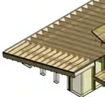
3D architectural rendering of the residence exterior showing roof framing and siding
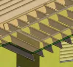
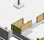
Diagram 101 - foundation wall intersection bar

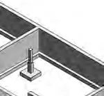
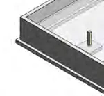
Diagram 102 - exterior pad footing showing min. 5/8" epoxy anchor (200mm embedment) and footing size

Diagram 103 - foundation wall corner bar

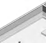
Diagram 104 - step footing showing 2 15M continuous at bottom of footing

Retaining wall diagram showing vertical reinforcing and drainage details

Retaining wall diagram showing perforated drain pipe and skimmer coat

Diagram 201 - top plate splice
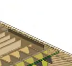
Diagram 202 - typ. wall framing

Diagram 203 - typ. 4 ply nailing

Diagram 204 - typ. shearwall showing sheathing and holddown details

Diagram 205 - flush beam to shear wall

Diagram 206 - drop beam to shear wall
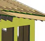
Diagram 207 - HDU holddown to concrete

Diagram 208 - STHD holddown

Detail 301 - base plate for steel post on stud wall
Detail 211 - typ. overhang detail


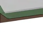


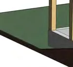


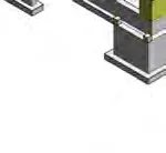
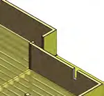
3D rendering of the concrete foundation structure
Main upper floor framing plan drawing with labels D, C, B, A and 1, 2, 3, 4, 5
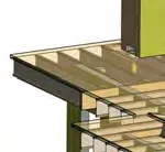
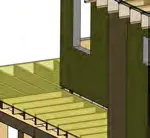
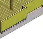
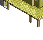
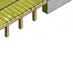
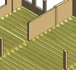
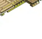
3D rendering of the upper floor framing


Main roof framing plan drawing with labels D, C, B, A and 1, 2, 3, 4, 5
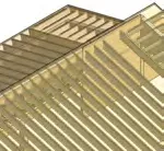
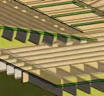
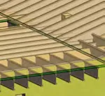
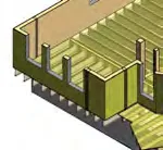
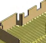
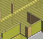
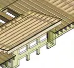
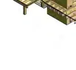
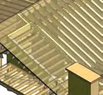
3D rendering of the roof framing
Detail 1/S4 - typical cross-section of foundation wall with floor system and footing

Detail 2/S4 - typical cross-section of foundation wall with ledger and footing
Detail 3/S4 - typical cross-section of foundation wall showing skim coat and exterior pad footing

Detail 4/S4 - cross-section of foundation wall at ledger showing handrail and floor system
Detail 5/S4 - section showing joist hanger and floor framing over foundation wall
Detail 7/S4 - elevator shaft and pit wall section

Detail 2/S4 - joist/beam framing detail

Detail 3/S4 - concrete pedestal and post connection detail

Detail 4/S4 - typical post to pad footing connection
Detail 12/S6 - timber post or built up post connection detail

Detail 11/S6 - roof framing arch and joist connection detail
Detail 10/S6 - typical roof framing and rafter detail with birdsmouth
Detail 9/S6 - roof framing rafter/joist connection at overhang

Detail 9/S6 - fascia arch and joist framing detail
Detail 8/S6 - typical roof and wall framing intersection detail

Detail 7/S6 - typical beam and stud wall framing detail