Appendix
roof framing plan
April 15, 2025Page 6052 sections
Structural engineering drawing showing the roof framing plan for a project at 12 Vickery Road.
12 Vickery RoadMark Buesink, P.Engstructural engineer
Mark Buesink, P.Eng, P.E. structural engineer
Page 605
roof framing plan
1/4" = 1'-0"
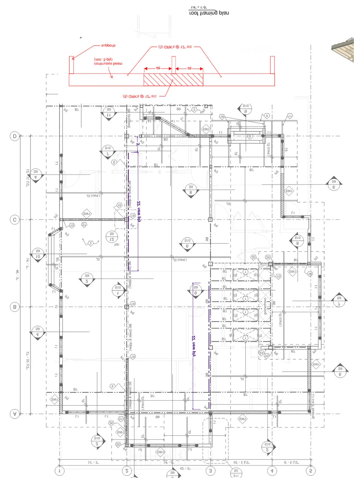
Continuous Beam Detail
- Member: continuous beam (min. 3-ply)
- Supports: Indicated at 4ft intervals.
- Fasteners:
- (5) GRK's @ 12" o/c
- (3) GRK's @ 12" o/c
Plan Dimensions and Callouts
- Horizontal Grid Dimensions: 11'- 3", 14'- 0", 10'- 3 1/2", 6'- 5 1/2" (Total: 42'- 0")
- Vertical Grid Dimensions: 17'- 10 1/2", 14'- 7", 13'- 11 1/2" (Total: 46'- 5")
- Key Annotations:
- 22' new ply (indicated along various support lines)
- B6 (lower & upper)
- J3 (cant.)
- (5) GRK's @ 12" o/c
- Various beam (B7, B3, B9), joist (J3, J2), and lintel (L1, L2) specifications.
- Shear wall (SW1) locations.
- Structural detail references (bubbles with numbers like 1/S10, 2/S10, 4/S9, etc.).
Page 605
Extracted from: 2025 04 15 Council Agenda - Agenda - Pdf