Appendix
Attachment 7 - Typical Retaining Wall Sections
September 1, 2015Page 641 section
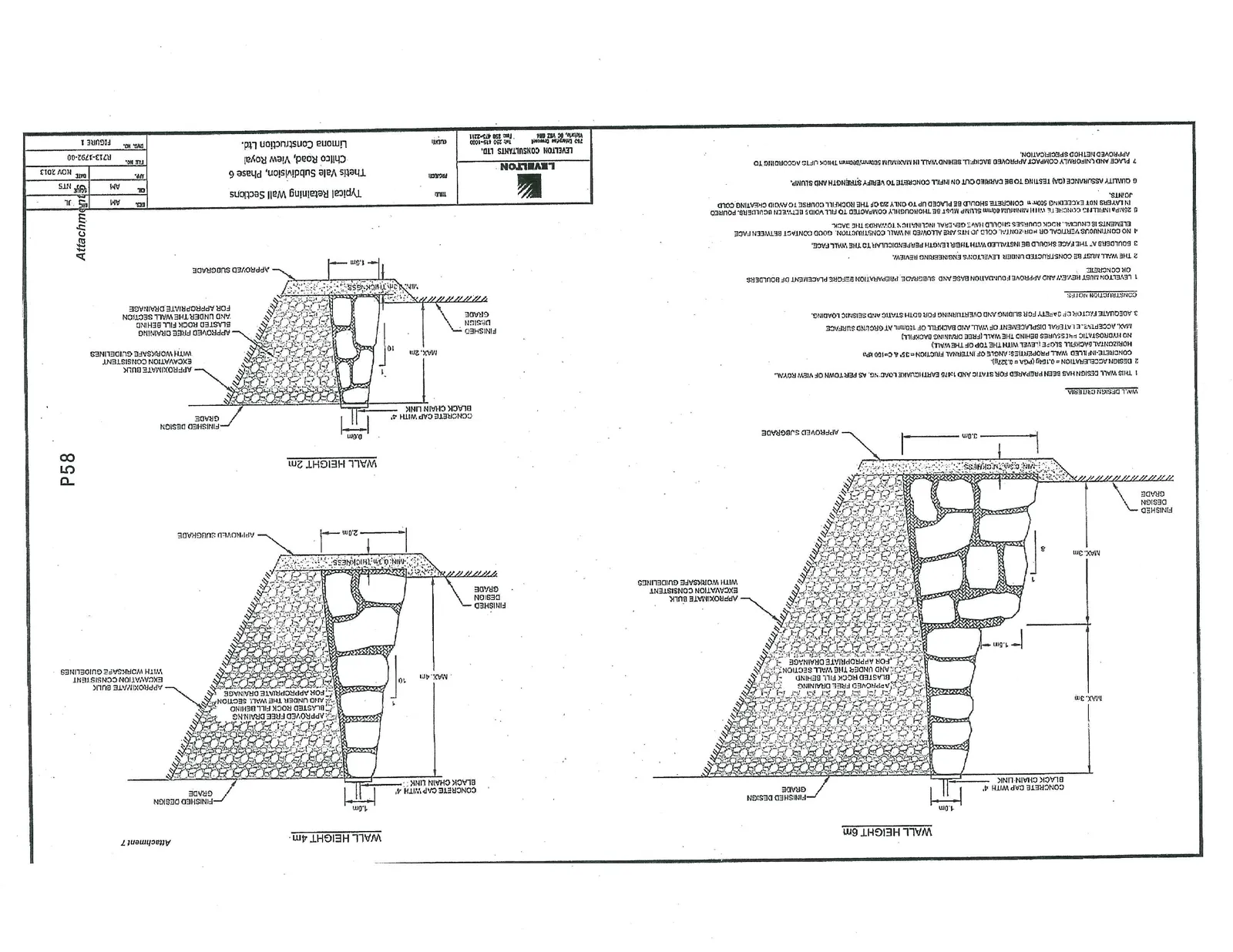
Technical drawings of typical mortared rock retaining wall sections for heights of 2m, 4m, and 6m.
November 2013Levelton Consultants Ltd.Thetis Vale Subdivision Phase 6
Typical Retaining Wall Sections
Attachment 7
Wall Height 6m
- Top Width: 1.0m
- Base Width: 3.0m
- Height Segments: Maximum 3m per section
- Features:
- Concrete cap with 4' black chain link fence.
- Finished design grade at top and bottom.
- Approved free draining blasted rock fill behind and under the wall section for appropriate drainage.
- Approximate bulk excavation consistent with WorkSafe guidelines.
- Approved subgrade.
- Boulders stacked with a 1.5m offset at the mid-section.
Wall Height 4m
- Top Width: 1.0m
- Base Width: 2.0m
- Maximum Height: 4m
- Features:
- Concrete cap with 4' black chain link fence.
- Finished design grade.
- Wall batter: 10°
- Minimum boulder thickness: 0.7m
- Approved free draining blasted rock fill behind and under the wall section for appropriate drainage.
- Approximate bulk excavation consistent with WorkSafe guidelines.
- Approved subgrade.
Wall Height 2m
- Top Width: 0.6m
- Base Width: 1.5m
- Maximum Height: 2m
- Features:
- Concrete cap with 4' black chain link fence.
- Finished design grade.
- Wall batter: 10°
- Minimum boulder thickness: 0.7m
- Approved free draining blasted rock fill behind and under the wall section for appropriate drainage.
- Approximate bulk excavation consistent with WorkSafe guidelines.
- Approved subgrade.
Wall Design Criteria
- This wall design has been prepared for static and 1:475 earthquake loading as per Town of View Royal.
- Design Acceleration = 0.198g (PGA = 0.337g). Concrete-or-soil wall properties: Angle of internal friction = 33° & C=100 kPa Horizontal backfill slope (level with the top of the wall) No hydrostatic pressure behind the wall (free draining backfill). Max. acceptable lateral displacement of wall and backfill of 100mm, at ground surface.
- Adequate factor of safety for sliding and overturning for both static and seismic loading.
Construction Notes
- Levelton must review and approve foundation base and subgrade preparation before placement of boulders or concrete.
- The wall must be constructed under Levelton's engineering review.
- Boulders at the face should be installed with their length perpendicular to the wall face.
- No continuous vertical or horizontal cold joints are allowed in wall construction. Good contact between face elements is critical. Rock surfaces should have rough facial irregularities to avoid creating cold joints.
- 20 MPa infilling concrete (100mm maximum slump) must be thoroughly compacted to fill voids between boulders. Pours in layers not exceeding 500mm. Concrete should be placed up to only 2/3 of the rock fill course to avoid creating cold joints.
- Quality assurance (QA) testing to be carried out on infill concrete to verify strength and slump.
- Place and carefully compact approved backfill behind wall in maximum 300mm/12 inch thick lifts according to approved method specification.
Project Information
| Field | Description |
|---|---|
| Title | Typical Retaining Wall Sections |
| Project | Thetis Vale Subdivision, Phase 6 |
| Location | Chilco Road, View Royal |
| Client | Limona Construction Ltd. |
| Consultant | Levelton Consultants Ltd. |
| Date | NOV 2013 |
| File No. | R713-1752-00 |
| Figure No. | Figure 1 |
| Designed By | AHL |
| Drawn By | AM |
| Checked By | AM |
| Scale | NTS |
Page 64
Extracted from: 2015 09 01 Council Agenda