RYZUK GEOTECHNICAL Geotechnical Investigation Report (March 15, 2019)
A comprehensive geotechnical investigation report and associated test pit data for the property at 1938 West Park Lane.
March 15, 2019 File No: 7877-3
Seymour Pacific Developments Ltd. 100 St. Ann’s Road Campbell River, BC V9W 4C4
Attn: Dave Cooper (By Email: dave.cooper@seymourpacific.ca)
Re: Proposed Residential Structure 1938 West Park Lane – View Royal, BC
As requested, we have completed a geotechnical investigation of the soil conditions at the referenced site. This report summarizes the results of our investigation and associated recommendations as related to the proposed development. Our work in this regard has been carried out in accordance with, and is subject to, the attached Terms of Engagement.
PROPOSED DEVELOPMENT
From the preliminary site plan that was provided to us by Seymour Pacific Developments, we understand that the proposed development will involve the subdivision of a portion of the existing lot near its southeast corner, which was previously the Thetis Lake Campground, and the construction of two six-story residential buildings and a surrounding parking lot. We anticipate that the proposed buildings will be wood framed with concrete foundations. The two residential buildings are oriented parallel to the south/southeast property line and are approximately 50 m long x 17 m wide. From the drawings provided, we understand that the main floor of both buildings will be constructed at an elevation of approximately 44.76 m. This will result in engineered fills of up to 6 m on the eastern half of the site, and cuts of up to 4 m on the western half of the site. We anticipate that retaining walls will be required to accommodate grade changes for the cuts and fills, and details can be provided for these once finished grades are known.
INVESTIGATION PROCEDURES
Our geotechnical investigation consisted of a review of available geological mapping and our file information from previous projects in the area, followed by our site attendance on February 21, 2019, to monitor a shallow subsurface test pit investigation. A review of geological mapping indicated that the soil conditions would consist of bedrock outcrops, with shallow soil cover overtop of bedrock. This was consistent with our previous project experience in the area. To confirm the information regarding the surrounding area and assess the thicknesses of fills and soils on site, six test pits were advanced at select locations across the site using a 20 ton excavator, to refusal depths varying between 2.2 and 4.3 m below existing grades. At the request of Seymour Pacific, the number and location of the test pits were limited during the investigation due to buried utilities in unknown locations across the site.
SURFACE AND SUBSURFACE CONDITIONS
The development site consists of a triangularly shaped lot bounded by Thetis Lake Park to the northwest and southeast, and the Trans Canada Highway to the southwest. The proposed structures will be constructed in the southeastern corner of the lot, within the footprint of the old camp grounds. Currently there are two small buildings on the site, with several small structures attached to them. In the southern portion of the site near the current alignment of West Park Lane, some paved areas are present. The remaining surfacing varies from native soil to fills, rubble, and a few small concrete pads from previously removed structures. There is minimal low-lying vegetation on the site, with a few scattered large trees around the perimeter. Topography slopes down from north to south across the site with about 8 m of relief, and more gently slopes down from the west property line to the center of the site with 6 m of relief. There are many localized flat areas across the site, with visible fill areas and cut slopes, indicating that significant grading has been done in the past. To the west and north of the eastern portion of the site, forested slopes exist with inclinations of between 20 and 30 degrees. The building and test pit locations are shown on the attached drawing no. 7877-3-1, dated March 2019.
Subsurface soil conditions were fairly uniform across the site and generally consisted of a layer of topsoil and/or fill to depths of between 0.2 and 1.9 m, over a thin layer of native mineral soils, atop bedrock. Native mineral soils for test pits TP19-01 to 05 consisted of stiff to very stiff light brown/bluish grey silty clay with trace sand. For test pit TP19-06 native mineral soils consisted of compact to dense light brown/reddish brown gravel with trace to some sand and trace to some silt. The surface of the bedrock was noted to be intact for test pits TP19-01 to 04, and lightly to moderately fractured/weathered in test pits TP19-05 and 06. Bedrock was noted to be dark, fine grained and hard, likely consisting of diorite or granodiorite. The surface of the bedrock in Victoria is generally erratic, and it is likely that depth of bedrock will fluctuate across the site.
Long term groundwater observations were not included in this scope of work, however minor seepage was observed in within the fill layer of TP19-04. We expect that perched water conditions may be experienced at the interface between the existing fill and native clay, and at the surface of the bedrock. These flows will likely be more prominent during periods of heavy and/or prolonged rainfall, due to the sloping nature of the site and the fact that the lot is undeveloped uphill of the site.
GEOTECHNICAL ASSESSMENT AND RECOMMENDATIONS
On the basis of our investigation, we do not foresee any unique geotechnical issues relating to development as proposed at this site. All existing fill materials will need to be removed from the building footprint areas and reinstated with engineered fill. We expect that the foundations will consist of conventional strip and pad footings bearing on stiff native clay, bedrock, or engineered fill placed upon native undisturbed strata. As noted above, we expect that retaining walls may be required to accommodate cuts and engineered fills. Rock excavation may be required near the west end of Building B where the grade is to be lowered and cut into the existing slope.
Excavation Considerations
It is expected that excavations of between 3 and 4 m will be required for the west end of Building B, up to 3 m to remove existing fills under both buildings, and up to 3 m deep for installing new utilities. During excavation works, we expect that temporary excavation cutslopes will be stable at the following general configurations:
- 0.75H:1.0V (horizontal to vertical) topsoil, existing fills, and compact gravel
- 0.5H:1.0V stiff clays
Cutslopes may need to be covered with polyethylene sheeting immediately after excavation to reduce erosion damage to cutslopes as a result of rainfall. Adjustments to the above configurations may be required upon site inspection during construction if variations of the soil conditions or seepage are observed, and due to the possible presence of existing utilities. According to WorkSafeBC guidelines, excavations deeper than 1.2 m must be inspected and approved by a qualified geotechnical professional.
Rock Excavation
At the western end of Building B, the proposed building elevation is expected to require approximately 4.5 m of excavation. Based on the nearest test pits, it is likely that bedrock will be located at a shallower depth, requiring rock removal. Since the observed bedrock in these areas was noted to be weathered at the surface but sound with 0.5 to 1.0 m depth, the removal method may consist of blasting or hoe-ramming depending on how much rock removal is required. In either case, care will need to be taken to avoid impacts on adjacent utilities in West Park Lane to the southeast, and/or the Trans Canada Highway to the south. The excavated rock is expected to be reasonably durable and is suitable for crushing and possibly re-use as granular fill on site (provided it is of suitable size and gradation), or for landscaping/retaining wall purposes. Any permanent exposed rock cuts will need to be assessed once excavated, to determine whether any scaling or further remediation measures will be required to stabilize the slopes.
Seismic Considerations
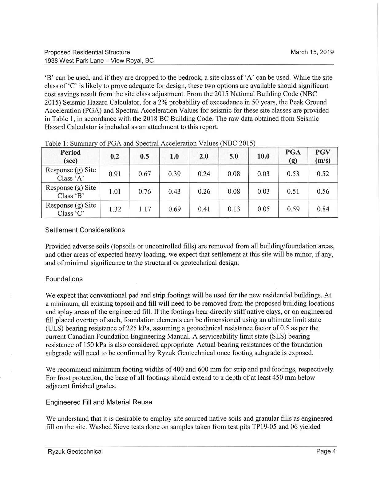
Greater Victoria is situated in a region of very high seismicity. Considerable earthquake risk exists, stemming from our proximity to the Cascadia subduction zone and numerous more local faults in southwestern BC and northwestern Washington State. Based on our observations onsite and knowledge of the soil conditions from past work in the area, we expect the building foundations to be located on engineered fill overtop of stiff native clays or bedrock. As such, we expect the Vs30 for the site to be greater than 360 m/s in all instances. Based on this result, the buildings can both be safely designed using a seismic site class of ‘C’. It should, however, be noted that if building foundations and/or seismic cores are dropped to within 3 m of bedrock, a site class improvement to ‘B’ can be used, and if they are dropped to the bedrock, a site class of ‘A’ can be used. While the site class of ‘C’ is likely to prove adequate for design, these two options are available should significant cost savings result from the site class adjustment. From the 2015 National Building Code (NBC 2015) Seismic Hazard Calculator, for a 2% probability of exceedance in 50 years, the Peak Ground Acceleration (PGA) and Spectral Acceleration Values for seismic for these site classes are provided in Table 1, in accordance with the 2018 BC Building Code. The raw data obtained from Seismic Hazard Calculator is included as an attachment to this report.
Table 1: Summary of PGA and Spectral Acceleration Values (NBC 2015)
| Period (sec) | 0.2 | 0.5 | 1.0 | 2.0 | 5.0 | 10.0 | PGA (g) | PGV (m/s) |
|---|---|---|---|---|---|---|---|---|
| Response (g) Site Class ‘A’ | 0.91 | 0.67 | 0.39 | 0.24 | 0.08 | 0.03 | 0.53 | 0.52 |
| Response (g) Site Class ‘B’ | 1.01 | 0.76 | 0.43 | 0.26 | 0.08 | 0.03 | 0.51 | 0.56 |
| Response (g) Site Class ‘C’ | 1.32 | 1.17 | 0.69 | 0.41 | 0.13 | 0.05 | 0.59 | 0.84 |
Settlement Considerations
Provided adverse soils (topsoils or uncontrolled fills) are removed from all building/foundation areas, and other areas of expected heavy loading, we expect that settlement at this site will be minor, if any, and of minimal significance to the structural or geotechnical design.
Foundations
We expect that conventional pad and strip footings will be used for the new residential buildings. At a minimum, all existing topsoil and fill will need to be removed from the proposed building locations and splay areas of the engineered fill. If the footings bear directly stiff native clays, or on engineered fill placed overtop of such, foundation elements can be dimensioned using an ultimate limit state (ULS) bearing resistance of 225 kPa, assuming a geotechnical resistance factor of 0.5 as per the current Canadian Foundation Engineering Manual. A serviceability limit state (SLS) bearing resistance of 150 kPa is also considered appropriate. Actual bearing resistances of the foundation subgrade will need to be confirmed by Ryzuk Geotechnical once footing subgrade is exposed.
We recommend minimum footing widths of 400 and 600 mm for strip and pad footings, respectively. For frost protection, the base of all footings should extend to a depth of at least 450 mm below adjacent finished grades.
Engineered Fill and Material Reuse
We understand that it is desirable to employ site sourced native soils and granular fills as engineered fill on the site. Washed Sieve tests done on samples taken from test pits TP19-05 and 06 yielded between 10.7% and 15.6% fines respectively. From these results, and subject to inspection at the time of construction, excavated native reddish brown sand and gravel may be suitable for reuse for engineered fill under roads and parking lots as sub-base fills (not part of the pavement structure), or general fill for landscaping purposes across the site. We expect that retaining walls may be desired to create level parking/landscape areas within the fill zones. Once finished elevations are better known we can provide details for such retaining walls if requested.
All engineered fill materials are to be compacted to a minimum of 95% of Standard Proctor Maximum Dry Density (SPMDD), with in-situ density testing conducted to ensure compaction in the engineered fill. The engineered fill must have a footprint that extends horizontally beyond the footings a distance equal to the thickness of the engineered fill, to provide adequate splay for foundation loads. In perimeter areas, it is inadvisable to have the fill splay extend beyond property lines.
Floor Slab
Use of a grade supported floor slab for the lower at grade slabs is considered feasible. A minimum 0.15 m of 19 mm minus crushed rock is recommended immediately beneath the slab, as well as a conventional subslab moisture barrier to minimize capillary rise of moisture into the slab. All subslab fill material should be free draining (contain less than 5% passing the #200 sieve) and be compacted to at least 95% of SPMDD.
Foundation Wall Backfill
Foundation walls should be backfilled with clean granular material per the Engineered Fill section above. Where the grade elevation differs significantly between the two sides of a perimeter wall, and the wall is free to rotate in order to develop the active earth pressure state (rotation of 0.1% of the wall height, non rigid wall), the wall should be designed to resist a lateral earth pressure (due to granular backfill) similar in magnitude and distribution to that of a fluid having a unit weight of 6.3 kN/m³. Lateral earth pressures due to floor loadings and/or foundation loads from adjacent portions of the building can be calculated assuming a lateral coefficient of 0.35. Where the wall cannot rotate (rigid wall), it should be designed to resist an at rest lateral earth pressure loading, similar in magnitude and distribution to that of a fluid having a unit weight of 8.6 kN/m³. In this case, lateral earth pressure due to floor loadings and/or foundation loads from adjacent buildings can be calculated assuming a lateral coefficient of 0.45. Equipment larger than a bobcat should not be allowed within 1.5 m of the foundation walls during backfilling.
Lateral earth pressures resulting from seismic activity can be calculated according to the following equations:
Non Rigid Wall: PE = 0.375 kh γ H²
Rigid Wall: PE = 0.5 kh γ H²
where:
- PE is the resultant force per unit length of wall;
- the coefficients of 0.375 and 0.5 are dimensionless;
- kh is the design peak horizontal ground acceleration coefficient;
- γ is the moist unit weight of the backfill material, which is approximately 20.4 kN/m³ for most granular backfill;
- H is the height of the wall
In the case of the non rigid wall, the backfill pressure distribution resulting from the earthquake loading can be assumed to be triangular, increasing from zero at the base of the wall to a maximum of 0.75 kh γ H at the top of the wall, with the resultant force acting at 0.67H above the base of the wall.
In the case of the rigid wall, the backfill pressure distribution resulting from the earthquake loading can be assumed to be parabolic, with the resultant force acting at 0.5H above the base of the wall.
For design purposes, the pressure distribution resulting from earthquake loading on the backfill should be added to either the active or at rest pressure distribution depending on whether the noted wall rotation can occur.
It should be noted that reduced pressures may be possible where the foundation walls are placed in close proximity to bedrock or through the use of light weight geofoam fill placed between the bedrock cut and the building walls. Should this be considered advantageous, these reduced loads can be addressed at a later date.
Foundation Drainage
Conventional perimeter foundation drainage tied into the recommended free draining backfill material will be suitable to limit hydrostatic pressure on the foundation walls. The foundation drain arrangement (perforated pipe and uniform gravel/drain rock) should be covered with non-woven geotextile filter fabric, or a suitably graded granular medium, to prevent migration of finer materials from the backfill into voids within the drain arrangement. Any pits below perimeter drainage are to be gravity drained or tanked and pumped.
Pavement / Road Structure Considerations
For general parking and light traffic areas, a pavement structure consisting of 50 mm of asphalt surfacing overlying at least 100 mm of 19 mm minus crushed base course and a minimum of 150 mm of 75 mm minus subbase is typically recommended over native soils, engineered fills over native soils, or bedrock. For heavier traffic areas, the thickness of the asphalt surfacing should be increased to a minimum of 75 mm and the base course thickened to 150 mm. Base and subbase layers should be compacted to 100% of SPMDD.
Geohazard Considerations
The western portion of the site is located adjacent to moderately steep areas, sloping up to the northwest at between 20 and 30 degrees. These slopes are undeveloped and vegetated with low-lying brush and large mature trees. While local steeper and flatter slopes were observed on and adjacent to the site, no significant rock slopes, or large unstable rocks were noted which may result in rockfall hazards. As well, we do not anticipate a risk of flooding or debris flows on or adjacent to the site as no well-defined channels were observed nearby. There was no evidence of landslides or landslips, such as scarps or debris flow, on or adjacent to the site. Due to the subsurface conditions, which consist of dense native mineral soils over bedrock, we expect that no risk of a deep-seated landslide on or directly adjacent to the site. Due to the forested groundcover and the relatively low snow-pack in the area, we do not expect that the site will be subject to avalanche risk. We anticipate that cuts into the existing slopes will be required near the northwest corner of the site, and recommend that further analysis of the slope be done once finished grades are known.
Given the above and provided our recommendations are followed, we do not expect that construction activity on site will adversely affect the slope stability or induce significant erosion. We do not expect that the development as proposed would adversely affect neighboring properties, and as such development of the site is considered feasible from a geotechnical engineering perspective. Accordingly, the site may be safely used for the use intended, that being multi family residential use, considering a design seismic event with a 2% probability of exceedance in 50 years.
CLOSURE
We trust the preceding is suitable for your purposes at present. Please don’t hesitate to contact our office if we can be of further assistance.
Yours very truly, Ryzuk Geotechnical
Shane Haxton, EIT Junior Engineer
Antoine Letendre, M.Eng, P.Eng. Project Engineer
Attachments:
- Terms of Engagement
- Drawing No. 7877-3-1 - Location Plan
- Table 1: Summary of Test Pit Information
- Seismic Hazard Calculations
TERMS OF ENGAGEMENT
GENERAL
Ryzuk Geotechnical (the Consultant) shall render the Services, as specified in the agreed Scope of Services, to the Client for this Project in accordance with the following terms of engagement. The Services, and any other associated documents, records or data, shall be carried out and/or prepared in accordance with generally accepted engineering practices in the location where the Services were performed. No other warranty, expressed or implied is made. The Consultant may, at its discretion and at any stage, engage sub-consultants to perform all or any part of the Services.
Ryzuk Geotechnical is a wholly owned subsidiary of C. N. Ryzuk & Associates Ltd.
COMPENSATION
All charges will be payable in Canadian Dollars. Invoices will be due and payable by the Client on receipt of the invoice without hold back. Interest on overdue accounts is 24% per annum.
REPRESENTATIVES
Each party shall designate a representative who is authorized to act on behalf of that party and receive notices under this Agreement.
TERMINATION
Either party may terminate this engagement without cause upon thirty (30) days' notice in writing. On termination by either party under this paragraph, the Client shall forthwith pay to the Consultant its Charges for the Services performed, including all expenses and other charges incurred by the Consultant for this Project.
If either party breaches this engagement, the non-defaulting party may terminate this engagement after giving seven (7) days' notice to remedy the breach. On termination by the Consultant under this paragraph, the Client shall forthwith pay to the Consultant its Charges for the Services performed to the date of termination, including all fees and charges for this Project.
ENVIRONMENTAL
The Consultant’s field investigation, laboratory testing and engineering recommendations will not address or evaluate pollution of soil or pollution of groundwater. The Consultant will cooperate with the Client’s environmental consultant during the field work phase of the investigation.
PROFESSIONAL RESPONSIBILITY
In performing the Services, the Consultant will provide and exercise the standard of care, skill and diligence required by customarily accepted professional practices and procedures normally provided in the performance of the Services contemplated in this engagement at the time when and the location in which the Services were performed.
INSURANCE
Ryzuk Geotechnical is covered by Professional Indemnity Insurance as follows:
- $2,000,000 each and every claim
- $4,000,000 aggregate
- $5,000,000 commercial/general liability coverage
LIMITATION OF LIABILITY
The Consultant shall not be responsible for:
- the failure of a contractor, retained by the Client, to perform the work required for the Project in accordance with the applicable contract documents;
- the design of or defects in equipment supplied or provided by the Client for incorporation into the Project;
- any cross-contamination resulting from subsurface investigations;
- any Project decisions made by the Client if the decisions were made without the advice of the Consultant or contrary to or inconsistent with the Consultant’s advice;
- any consequential loss, injury or damages suffered by the Client, including but not limited to loss of use, earnings and business interruption;
- the unauthorized distribution of any confidential document or report prepared by or on behalf of the consultant for the exclusive use of the Client
- Subsurface structures and utilities
The Consultant will make all reasonable efforts prior to and during subsurface site investigations to minimize the risk of damaging any subsurface utilities/mains. If, in the unlikely event that damage is incurred where utilities were unmarked and/or undetected, the Consultant will not be held responsible for damages to the site or surrounding areas, utilities/mains or drilling equipment or the cost of any repairs.
The total amount of all claims the Client may have against the Consultant or any present or former partner, executive officer, director, stockholder or employee thereof under this engagement, including but not limited to claims for negligence, negligent misrepresentation and breach of contract, shall be strictly limited to the amount of any professional liability insurance the Consultant may have available for such claims.
No claim may be brought against the Consultant in contract or tort more than two (2) years after the date of discovery of such defect.
DOCUMENTS AND REPORTING
All of the documents prepared by the Consultant or on behalf of the Consultant in connection with the Project are instruments of service for the execution of the Project. The Consultant retains the property and copyright in these documents, whether the Project is executed or not. These documents may not be used on any other project without the prior written agreement of the Consultant.
The documents have been prepared specifically for the Project, and are applicable only in the case where there has been no physical alteration to, or deviation from any of the information provided to the Consultant by the Client or agents of the Client. The Client may, in light of such alterations or deviations, request that the Consultant review and revise these documents.
The identification and classification as to the extent, properties or type of soils or other materials at the Project site has been based upon investigation and interpretation consistent with the accepted standard of care in the engineering consulting practice in the location where the Services were performed. Due to the nature of geotechnical engineering, there is an inherent risk that some conditions will not be detected at the Project site, and that actual subsurface conditions may vary considerably from investigation points. The Client must be aware of, and accept this risk, as must any other party making use of any documents prepared by the Consultant regarding the Project.
Any conclusions and recommendations provided within any document prepared by the Consultant for the Client has been based on the investigative information undertaken by the Consultant, and any additional information provided to the Consultant by the Client or agents of the Client. The Consultant accepts no responsibility for any associated deficiency or inaccuracy as the result of a miss-statement or receipt of fraudulent information.
JOBSITE SAFETY AND CONTROL
The Client acknowledges that control of the jobsite lies solely with the Client, his agents or contractors. The presence of the Consultant’s personnel on the site does not relieve the Client, his agents or contractors from their responsibilities for site safety. Accordingly, the Client must endeavor to inform the Consultant of all hazardous or otherwise dangerous conditions at the Project site of which the Client is aware.
The client must acknowledge that during the course of a geotechnical investigation, it is possible that a previously unknown hazard may be discovered. In this event, the Client recognizes that such a hazard may result in the necessity to undertake procedures which ensure the safety and protection of personnel and/or the environment. The Client shall be responsible for payment of any additional expenses incurred as a result of such discoveries, and recognizes that under certain circumstances, discovery of hazardous conditions or elements requires that regulatory agencies must be informed. The Client shall not bring about any action or dispute against the Consultant as a result of such notification.
FIELD SERVICES
Where applicable, field services recommended for the Project are the minimum necessary, in the sole discretion of the Consultant, to observe whether the work or a contractor retained by the Client is being carried out in general conformity with the intent of the Services. Any reduction from the level of services recommended will result in the Consultant providing qualified certifications for the work.
DISPUTE RESOLUTION
If requested in writing by either the Client or the Consultant, the Client and the Consultant shall attempt to resolve any dispute between them arising out of or in connection with this Agreement by entering into structured non-binding negotiations with the assistance of a mediator on a without prejudice basis. The mediator shall be appointed by agreement of the parties. If a dispute cannot be settled within a period of thirty (30) calendar days with the mediator, the dispute shall be referred to and finally resolved by arbitration under the rules of the arbitrator appointed by agreement of the parties or by reference to a Judge of the British Columbia Court.
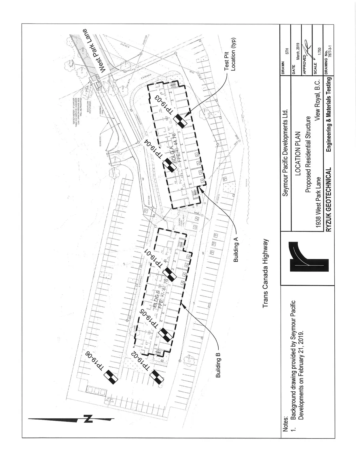
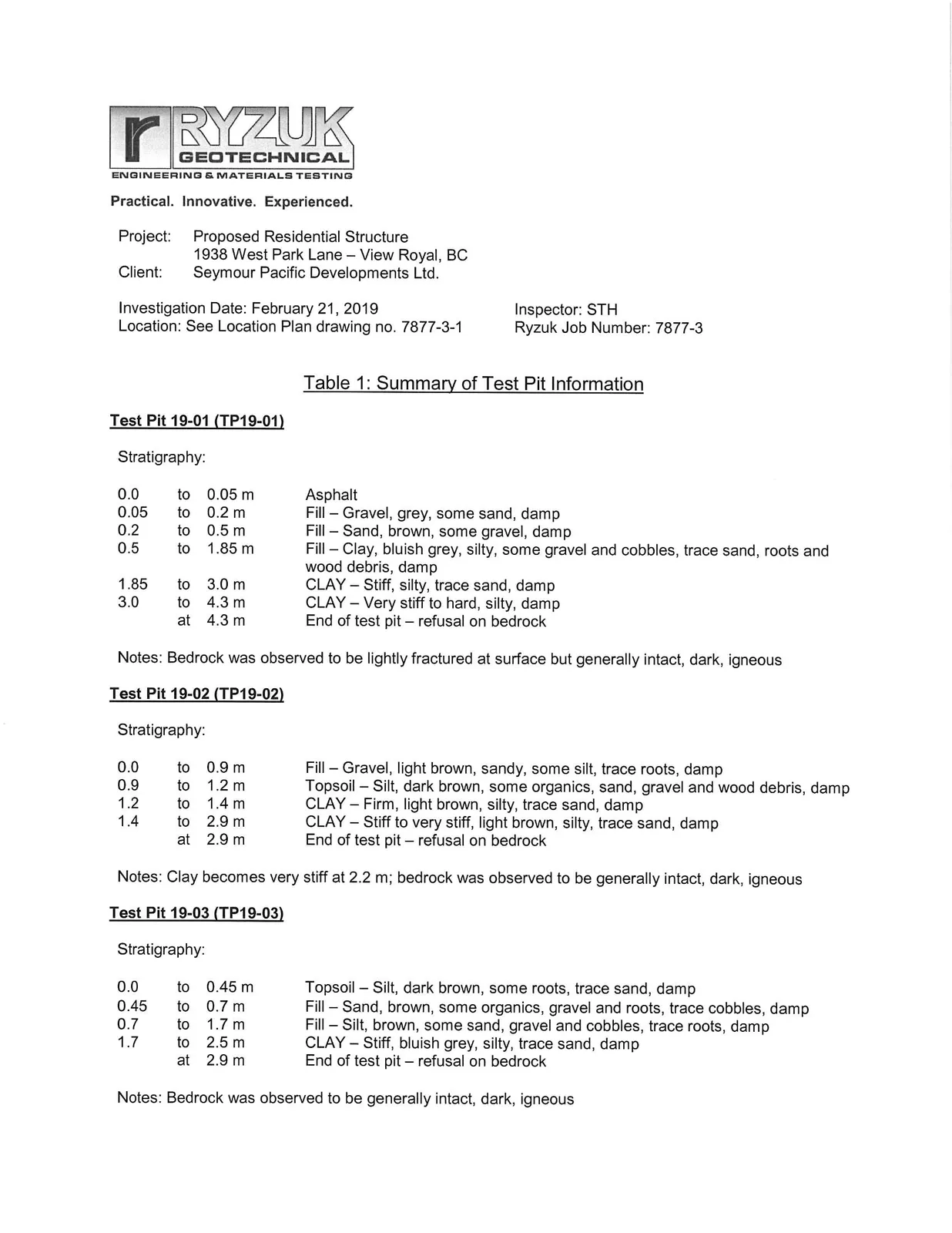
Table 1: Summary of Test Pit Information
Test Pit 19-01 (TP19-01)
Stratigraphy:
- 0.0 to 0.05 m: Asphalt
- 0.05 to 0.2 m: Fill - Gravel, grey, some sand, damp
- 0.2 to 0.5 m: Fill - Sand, brown, some gravel, damp
- 0.5 to 1.85 m: Fill - Clay, bluish grey, silty, some gravel and cobbles, trace sand, roots and wood debris, damp
- 1.85 to 3.0 m: CLAY – Stiff, silty, trace sand, damp
- 3.0 to 4.3 m: CLAY – Very stiff to hard, silty, damp
- at 4.3 m: End of test pit – refusal on bedrock
Notes: Bedrock was observed to be lightly fractured at surface but generally intact, dark, igneous
Test Pit 19-02 (TP19-02)
Stratigraphy:
- 0.0 to 0.9 m: Fill – Gravel, light brown, sandy, some silt, trace roots, damp
- 0.9 to 1.2 m: Topsoil – Silt, dark brown, some organics, sand, gravel and wood debris, damp
- 1.2 to 1.4 m: CLAY – Firm, light brown, silty, trace sand, damp
- 1.4 to 2.9 m: CLAY – Stiff to very stiff, light brown, silty, trace sand, damp
- at 2.9 m: End of test pit – refusal on bedrock
Notes: Clay becomes very stiff at 2.2 m; bedrock was observed to be generally intact, dark, igneous
Test Pit 19-03 (TP19-03)
Stratigraphy:
- 0.0 to 0.45 m: Topsoil – Silt, dark brown, some roots, trace sand, damp
- 0.45 to 0.7 m: Fill – Sand, brown, some organics, gravel and roots, trace cobbles, damp
- 0.7 to 1.7 m: Fill – Silt, brown, some sand, gravel and cobbles, trace roots, damp
- 1.7 to 2.5 m: CLAY – Stiff, bluish grey, silty, trace sand, damp
- at 2.9 m: End of test pit – refusal on bedrock
Notes: Bedrock was observed to be generally intact, dark, igneous
Document Images
(10)