This site is in beta — data may be incomplete and features are still being added.
Committee of the Whole/Documents/Engineering Drawing - Rock Wall/Soil Stabilization Profile
Appendix

Engineering Drawing - Rock Wall/Soil Stabilization Profile

May 11, 2021Page 2351 section

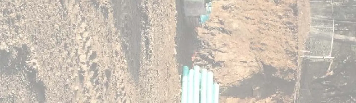
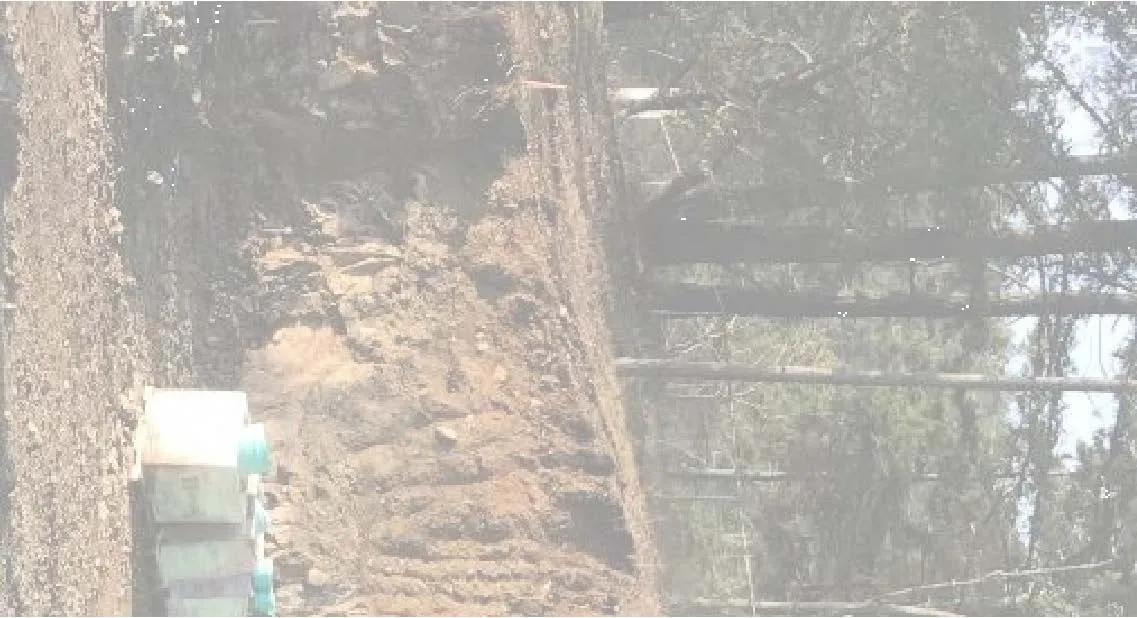
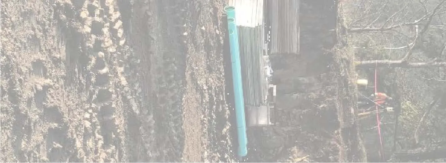
Profile drawing showing the localized rock support anchors and mesh lacing for slope stabilization.

Drawing No: 7877-7-2Approximate mesh height: 10.5 mMaximum 24 m sections for the rock wall

ROCK WALL/SOIL STABILIZATION - PROFILE

Project: Proposed Residential Development Location: 1938 West Park Lane, View Royal, B.C. Client: Seymour Pacific Developments Ltd. Status: ISSUED FOR DISCUSSION: 2020-03-26

Profile Overview

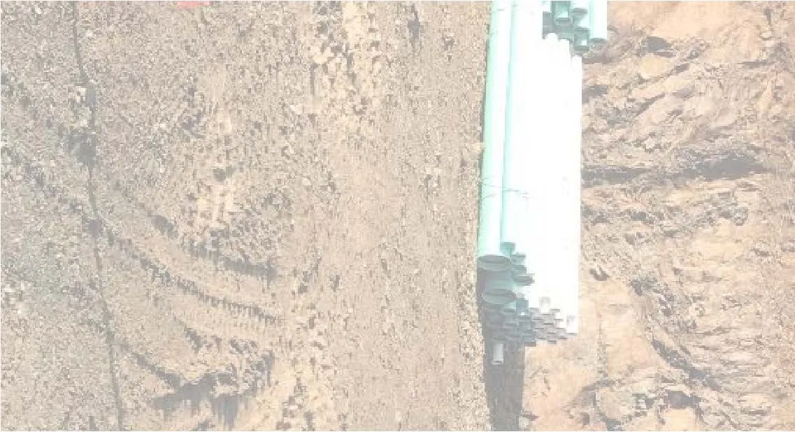
The following images represent fragments of the background site photograph and technical drawing for the rock wall and soil stabilization project:

Site photograph fragment showing ground surface
Site photograph fragment showing rock face and trees
Site photograph fragment showing tree branches
Site photograph fragment showing tree tops against the sky
Site photograph fragment showing ground area with piping
Site photograph fragment showing rock wall with stabilization mesh
Site photograph fragment showing detailed view of stabilization mesh
Site photograph fragment showing foliage and sky
Site photograph fragment showing rocky ground near the wall base
Site photograph fragment showing upper portion of the mesh system
Site photograph fragment showing central rock face area
Site photograph fragment showing mesh coverage on rock
Site photograph fragment showing utility pipes along the wall base
Site photograph fragment showing stabilization mesh on rock
Site photograph fragment showing rock and vegetation
Site photograph fragment showing foliage against a bright sky
Site photograph fragment showing cleared ground surface
Site photograph fragment showing mesh detail on the rock face
Site photograph fragment showing mesh and support components
Site photograph fragment showing upper tree canopy
Site photograph fragment showing lower rock wall section
Site photograph fragment showing canopy detail
Site photograph fragment showing ground surface near work area
Site photograph fragment showing rock wall with mesh overlay
Site photograph fragment showing detailed rock wall texture
Site photograph fragment showing base area of the stabilization project

Technical Annotations and Specifications

The profile drawing includes the following technical details and annotations:

  • Stabilization Method: Stabilization method to be determined based on actual conditions encountered.
  • Backfill: Sloped backfill soils are indicated above the block wall structure.
  • Anchors and Cables:
    • 22 mm end main anchor: Reference Detail D.
    • 19 mm suspension cable: Mesh lacing as per note 13.
    • Intermediate main anchor and Auxilliary anchor/cable: Reference Detail A.
    • 19 mm end main anchors: Spaced 200 mm between sections.
    • 19 mm end cable.
    • Localized rock support anchors (rock bolts): To be installed where necessary.
  • Mesh System Details:
    • Mesh: Applied to the rock face.
    • Mesh Height: Approximate mesh height of 10.5 m.
    • Lacing: Mesh laced between adjacent sections with 200 mm overlap on both sides.
    • Overlap: Overlap minimum 200 mm. Connection as per Detail E.
  • Project Layout:
    • Maximum Section Length: 24 m sections.
    • Slope Crest/Property Line: Indicated at the top of the stabilized rock face.
    • Anticipated Parking Elevation: Indicated at the base of the rock wall and mesh stabilization system.

Project Information

Field Information
Drawn By CPAS
Date March, 2020
Scale NTS (Not to Scale)
Drawing Number 7877-7-2
Engineering Firm RYZUK GEOTECHNICAL - Engineering & Materials Testing

Notes: (The notes section is blank on this drawing page.)

Page 235

Document Images

(1)
Document image
Extracted from: 2021 05 11 Committee of the Whole Agenda - Agenda - Pdf