Appendix
Rock Drapery Specifications
May 11, 2021Page 2364 sections
Detailed engineering specifications and MOTI standard drawings for rock slope mesh installation.
Standard: MoTI - 2018 Design Build Standard SpecificationsMesh type: 11 gauge hexagonal triple twist gabion meshCorrosion protection: hot-dip galvanized or stainless steel
Rock Drapery Specifications
- Rock drapery to be in general conformance with Section 207 of the Ministry of Transportation and Infrastructure (MOTI) - 2018 Design Build Standard Specifications for Highway Construction document unless otherwise stated in specifications below.
- All slope meshing/drapery materials to be hot-dip galvanized or stainless steel.
- Required wire mesh height for each section to be determined by contractor depending on existing and final site grades.
- Wire mesh to be installed to 1.2 m above base of excavation.
- Drilling and meshing work must be coordinated with blasting and slope rock removal.
- We recommend to mark/layout the slope stabilization area (boundaries, corners, mesh width, rock bolts) with paint prior to starting of the work so any obstacles could be visually assessed.
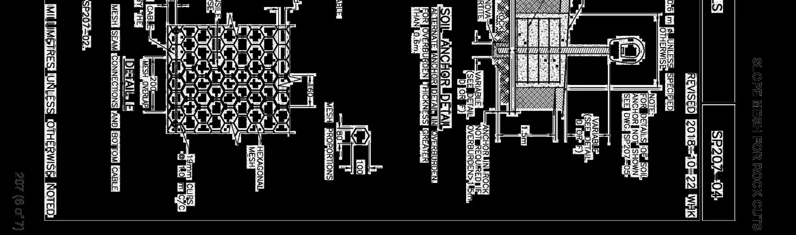
- The installation should proceed as follows: 7.1. Hydroscaling of slope. 7.2. Drilling of the end main anchors and intermediate main anchors according to the design spacing. 7.3. Install rock stabilization anchors (rock bolts) and mesh support as indicated by Ryzuk . 7.4. Grout infill anchors. 7.5. Hang wire mesh rolls from top anchors temporarily and unroll mesh ensuring a minimum 200 mm overlap. 7.6. Install suspension rope at top of wire mesh and install 6 mm lacing cable.
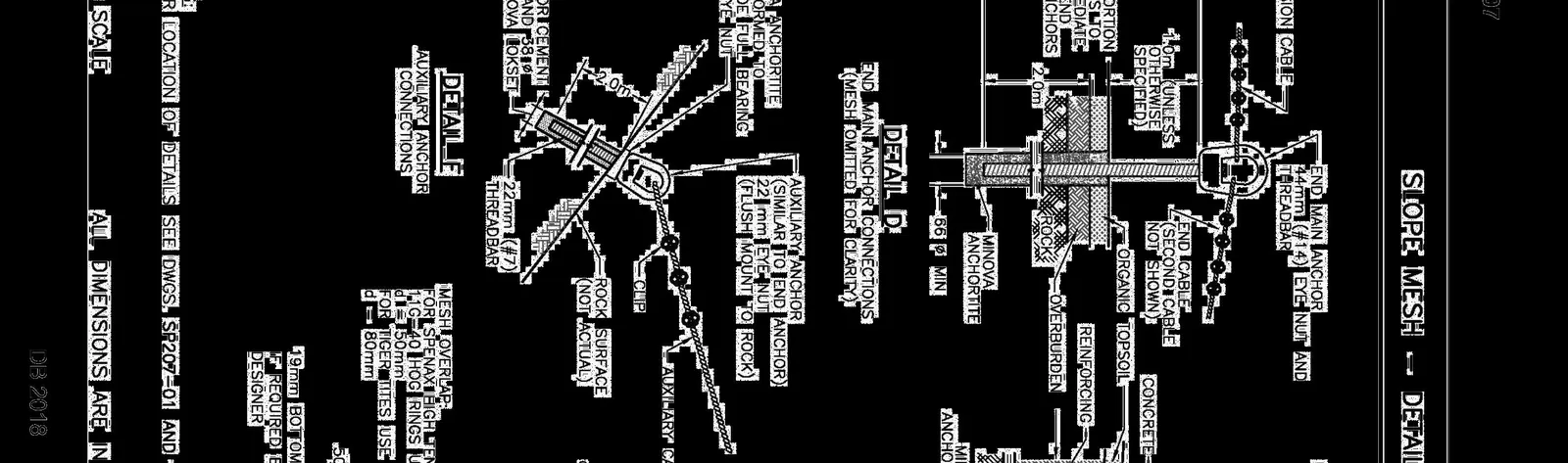
- End main anchors and intermediate main anchors to consist of galvanized DYWIDAG #14 eye nut and threadbar, embedded at least 2 m into rock. To be grouted into a ≥ 66 mm Ø hole using Minova Anchorite or approved equivalent.
- Auxilary anchors to consist of galvanized DYWIDAG #8 eye nut and threadbar, embedded at least 2 m into rock. To be grouted into a 45 mm Ø hole using non-shrinking cementitious Basailite microsil anchor grout or approved equivalent, with a minimum compressive strength of 20 MPa in 48 hours, and 40 MPa in 28 days.
- Rock support anchors to consist of galvanized DYWIDAG #8 threadbar and anchor plate installed at 10° and embedded at least 3 metres. To be grouted into a 45 mm Ø hole using non-shrinking cementitious Basalite microsil anchor grout or approved equivalent, with a minimum compressive strength of 20 MPa in 48 hours, and 40 MPa in 28 days. Rock bolts to be hand tightened with a large wrench.
- Suspension and end cable to consist of 19 mm Ø unspliced fibre core cables conforming to CSA G4. Loops to be connected with 4 clips within a length of 460 mm (torque = 175 Nm).
- Auxilar cables to consist of 16 mm Ø unspliced fibre core cables conforming to CSA G4. Loops to be connected with 3 clips within a length of 300 mm (torque = 113 Nm).
- Lacing cable to be looped through each mesh opening and around suspension cable. Loops to be connected with at least 3 clips (torque = 54 Nm). Final number of clips to be determined during construction.
- Mesh shall be 11 gauge (2.95 mm dia.) hexagonal triple twist gabion type mesh and be in accordance with MoTI spec. 207.11.01. No horizontal mesh splicing, vertical overlap to be minimum of 200 mm.
- Maximum extent of a mesh section to be 24 m horizontally.
- Meshing and rock anchor installation must be monitored by Ryzuk Geotechnical.
Page 236
MOTI - 2018 Design Build Standard Specifications for Highway Construction Section 207 - Slope Mesh for Rock Cuts, SP207-03
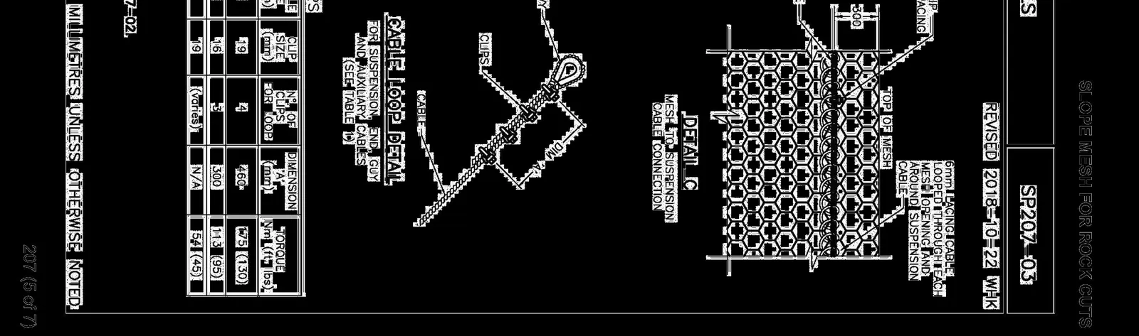
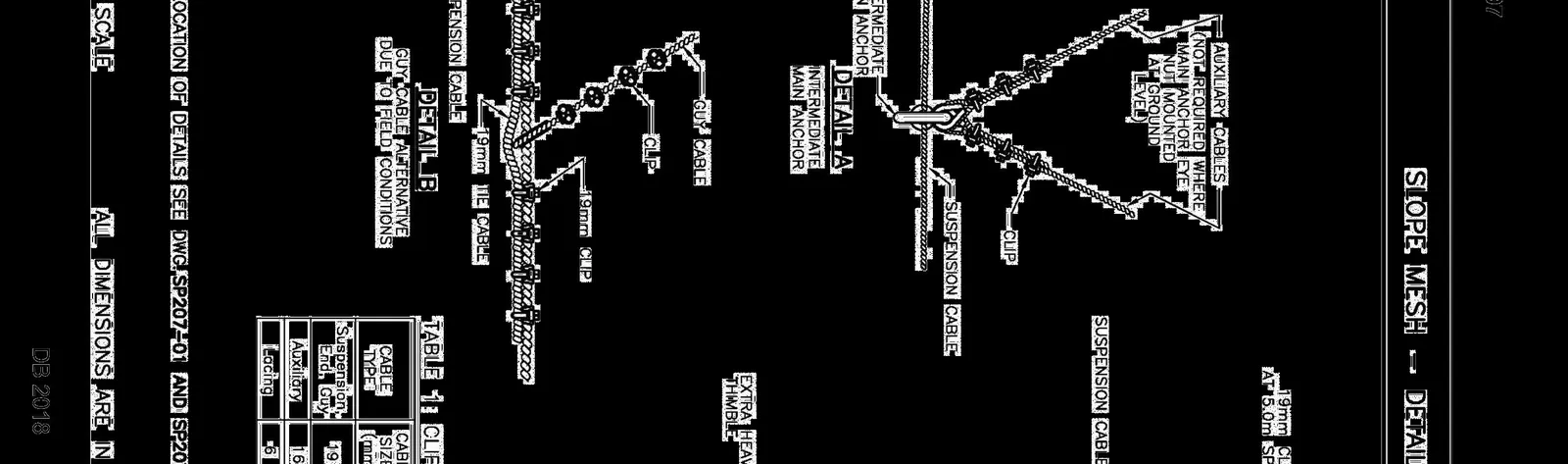
TABLE 1: CLIPS
| CABLE TYPE | CABLE SIZE (mm) | CLIP SIZE (mm) | Nº. OF CLIPS FOR LOOP | DIMENSION 'A' (mm) | TORQUE Nm (ft. lbs) |
|---|---|---|---|---|---|
| Suspension, End, Guy | 19 | 19 | 4 | 460 | 175 (130) |
| Auxiliary | 16 | 16 | 3 | 300 | 113 (95) |
| Lacing | 6 | 19 | (varies) | N/A | 54 (45) |
Page 236
MOTI - 2018 Design Build Standard Specifications for Highway Construction Section 207 - Slope Mesh for Rock Cuts, SP207-04
Page 236
Project Information
Project: Proposed Residential Development Address: 1938 West Park Lane, View Royal, B.C. Client: Seymour Pacific Developments Ltd. Engineering Firm: RYZUK GEOTECHNICAL Engineering & Materials Testing Drawing Title: DETAILS Drawing No: 7877-7-3 Date: March, 2020 Status: ISSUED FOR DISCUSSION: 2020-03-26 Drawn By: CPAS / RN Scale: NTS
Page 236
Document Images
(1)
Extracted from: 2021 05 11 Committee of the Whole Agenda - Agenda - Pdf