Proposed Retaining Walls Geotechnical Report - 315 Stewart Avenue
A geotechnical assessment and design recommendations for the replacement of failing creosote walls with new boulder retaining structures.
April 29, 2021 Revised: May 20, 2021 File No: 9087-10
Coastal Force Construction Ltd 725 Race Passage Close Sooke, BC V9Z 1C5
Attn: Bruce Sutton (By E-mail: bruce@coastalforceconstruction.com)
Re: Proposed Retaining Walls 315 Stewart Avenue – View Royal, BC
As requested, we attended the referenced site on March 29, 2021, to complete a visual geotechnical assessment of the property as such relates to the replacement of a number of existing landscape retaining walls. The site is located within the Environmental Protection & Natural Hazard Development Permit Area, in accordance with the View Royal Official Community Plan. Our associated observations, comments, and recommendations in this regard are summarized herein. Our work has been carried out in accordance with, and is subject to, the previously provided Terms of Engagement.
The site is a roughly rectangular shaped waterfront lot, which is bounded by Stewart Ave to the east, neighbouring residential properties to the north and south, and the marine foreshore of Helmcken Bay (Esquimalt Harbour) to the west. It is currently vacant except for a garage structure in the central portion. The site terrain consists of a relatively level to gently sloping upland plateau in the east, transitioning mid way through the lot to a slope down to the foreshore. The slope itself is generally comprised of a series of level benches retained by walls between 1.2 m and 1.8 m in height, with stairs on grade leading to the foreshore and to a ramp to the existing dock. Several mature trees are present upon the slope and on the bank above the foreshore. The dock ramp is supported atop an existing seawall, which is 1.8 m high in the south transitioning to 1.2 m high in the north. Overall slope relief within the western half of the site is approximately 8.5 m vertical over a distance of approximately 20 m horizontal for an average inclination of 23 degrees from horizontal. The beach consists of irregularly outcropping bedrock which comprises the toe of the slope over the south and very north, with the area between comprising a pocket of mud/clay overlain by a thin gravel layer.
The existing walls are generally comprised of stacked horizontal logs or wooden ties, with the exception of the northern portion and very south corner of seawall as well as the walls upon the slope south of the stairs on grade, which are comprised of concrete blocks. The concrete portions of seawall appear to have a poured concrete footing. The wooden walls are intact in some areas and have collapsed in others, and the wood has begun to rot throughout. Where visible, wall backfill was observed to consist of non-select fill including mixed soil/organics, concrete blocks, cobbles/boulders, tires and other garbage/debris.
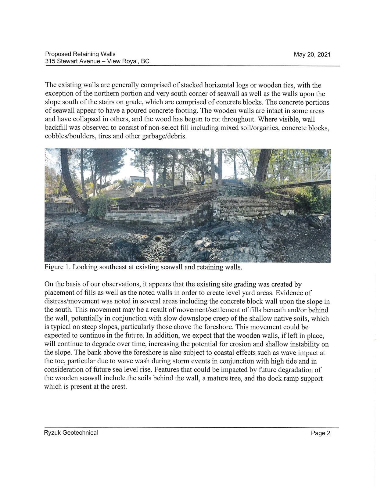
On the basis of our observations, it appears that the existing site grading was created by placement of fills as well as the noted walls in order to create level yard areas. Evidence of distress/movement was noted in several areas including the concrete block wall upon the slope in the south. This movement may be a result of movement/settlement of fills beneath and/or behind the wall, potentially in conjunction with slow downslope creep of the shallow native soils, which is typical on steep slopes, particularly those above the foreshore. This movement could be expected to continue in the future. In addition, we expect that the wooden walls, if left in place, will continue to degrade over time, increasing the potential for erosion and shallow instability on the slope. The bank above the foreshore is also subject to coastal effects such as wave impact at the toe, particular due to wave wash during storm events in conjunction with high tide and in consideration of future sea level rise. Features that could be impacted by future degradation of the wooden seawall include the soils behind the wall, a mature tree, and the dock ramp support which is present at the crest.
We understand it is proposed to replace the wooden seawall, as well as all the other walls on the slope, with boulder stacked walls. The trees would be retained. A patio surface would be included within the yard. We recommend that proposed works balance cuts and fills and avoid inducing substantial additional loading on the existing slope, to avoid accelerating the rate of shallow creep and unduly influencing slope stability. Based on our discussions, the slope grading will remain similar in some areas and be re-tiered in others. The attached Location Plan shows the approximate location of the proposed seawall and retaining walls.
We are aware that soft shore/Green Shores stabilization techniques are favoured by the local municipalities. We consider that given the existing vertical seawall arrangement, a wall of similar height and inclination will be necessary to maintain the slope in its current state. Boulder stacked walls are recommended as an option that protect steep banks by providing resistance to wave erosion, provide surface roughness similar to the existing bedrock beach outcrop (rather than the smooth/hard finish of concrete block or cast in place), allow vegetative growth in interstices, and are relatively simple/economical to construct.
The boulder stacked seawall will be founded atop intact bedrock. Existing concrete, where present, may be evaluated at the time of construction for re use in place. The bedrock is undulating/sloping in nature. Base boulders should be placed on a relatively level surface sloping slightly away from the beach, unless well interlocking with the profile of the bedrock. It may be necessary to chip the rock subgrade level, dowel the base boulders into rock, or form and pour a concrete curb/foundation to prepare the subgrade surface for the base boulders. Boulder stacked walls should consist of sound boulders of durable rock sized a minimum of 1.0 to 1.2 m in diameter, stacked in an interlocking fashion with a nominal front face batter of 1/10. We have also provided an option for the uppermost boulder stacked wall to be a maximum height of 3.2 m, provided such is battered at 3/4 Horizontal to 1 Vertical (3/4H to 1V). Where bedrock is not present, base boulders should be keyed into native, undisturbed mineral soil a minimum of 0.5 m. Boulder stacked wall details are provided in the attached section drawings entitled 'Seawall' and 'Tiered Walls.'
Backfill behind the walls should consist of a minimum 0.3 m wide drainage layer of granular backfill. For seawalls, we typically recommend a 10kg class rip rap or approved alternate. It is critical that the gradation of the seawall backfill match the specification, in order to resist erosion of the material from behind the wall through the face where gaps between boulders exist. A medium weight non-woven geotextile is recommended against the seawall temporary bank cutslope and behind the backfill in order to prevent migration of fines from the slope soils into the granular backfill. For retaining walls not interacting with the shoreline, any free draining granular fill could be used. Well graded and thoroughly compacted fill is recommended where such will support finished surfaces atop the wall. Clear drain rock could be used if desired but should be fully wrapped with medium weight geotextile in order to prevent migration of fines into the voids within the drain rock. A 0.45 m layer of planting soil (specified by others) will be placed in front of/behind walls in yard areas. Attention should be paid to gradational compatibility to prevent the planting soil from hourglassing into the voids within the free draining backfill.
Tiered walls, where proposed, should be located such that the upper tier is set back behind a minimum 1H to 1V plane extending from the base of the lower wall, so as not to induce a surcharge on the lower wall. The noted walls are intended as landscaping walls only and have been not designed for support of additional structures above. Foundations for structures upslope of the retaining walls should also be located behind a 1H to 1V plane from the base of the upper wall.
Given the scope of work is to replace existing retaining walls in similar locations, and that drainage will be provided through the face of the walls, no substantial changes to the existing stormwater regime are anticipated as a result of the work.
Based on the above, and provided our recommendations are followed, we consider the construction of the noted retaining walls can be completed without significant adverse impacts to slope stability or erosion on this or neighbouring properties.
We trust the preceding is suitable for your purposes at present. If you have any questions, or require anything further, please do not hesitate to contact us.
Yours very truly, Ryzuk Geotechnical
Laura Lessingham, P.Geo. Intermediate Geoscientist
Attachments:
- Location Plan
- Seawall section
- Tiered Walls section
LOCATION PLAN
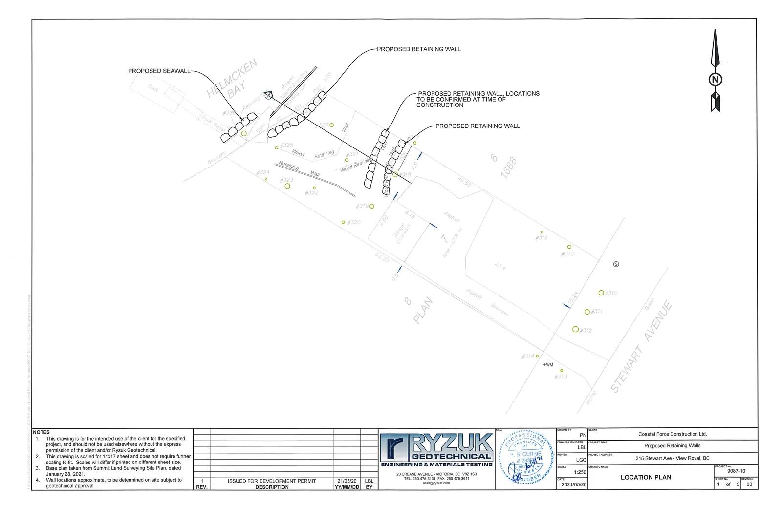
NOTES
- This drawing is for the intended use of the client for the specified project, and should not be used elsewhere without the express permission of the client and/or Ryzuk Geotechnical.
- This drawing is scaled for 11x17 sheet and does not require further scaling to fit. Scales will differ if printed on different sheet size.
- Base plan taken from Summit Land Surveying Site Plan, dated January 28, 2021.
- Wall locations approximate, to be determined on site subject to geotechnical approval.
TIERED WALLS
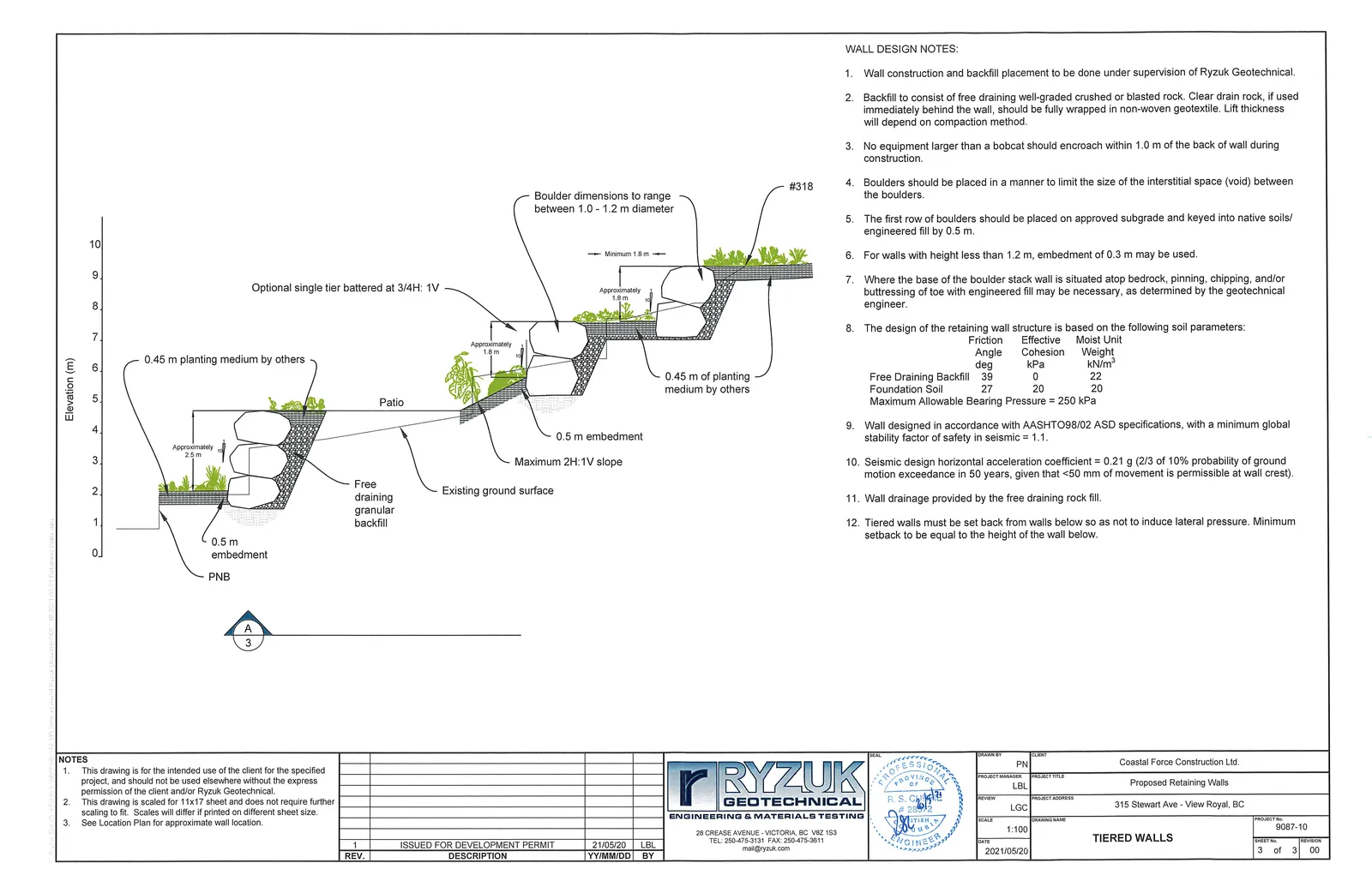
WALL DESIGN NOTES:
- Wall construction and backfill placement to be done under supervision of Ryzuk Geotechnical.
- Backfill to consist of free draining well-graded crushed or blasted rock. Clear drain rock, if used immediately behind the wall, should be fully wrapped in non-woven geotextile. Lift thickness will depend on compaction method.
- No equipment larger than a bobcat should encroach within 1.0 m of the back of wall during construction.
- Boulders should be placed in a manner to limit the size of the interstitial space (void) between the boulders.
- The first row of boulders should be placed on approved subgrade and keyed into native soils/engineered fill by 0.5 m.
- For walls with height less than 1.2 m, embedment of 0.3 m may be used.
- Where the base of the boulder stack wall is situated atop bedrock, pinning, chipping, and/or buttressing of toe with engineered fill may be necessary, as determined by the geotechnical engineer.
- The design of the retaining wall structure is based on the following soil parameters:
| Material | Friction Angle (deg) | Effective Cohesion (kPa) | Moist Unit Weight (kN/m³) |
|---|---|---|---|
| Free Draining Backfill | 39 | 0 | 22 |
| Foundation Soil | 27 | 20 | 20 |
Maximum Allowable Bearing Pressure = 250 kPa
- Wall designed in accordance with AASHTO98/02 ASD specifications, with a minimum global stability factor of safety in seismic = 1.1.
- Seismic design horizontal acceleration coefficient = 0.21 g (2/3 of 10% probability of ground motion exceedance in 50 years, given that <50 mm of movement is permissible at wall crest).
- Wall drainage provided by the free draining rock fill.
- Tiered walls must be set back from walls below so as not to induce lateral pressure. Minimum setback to be equal to the height of the wall below.
NOTES
- This drawing is for the intended use of the client for the specified project, and should not be used elsewhere without the express permission of the client and/or Ryzuk Geotechnical.
- This drawing is scaled for 11x17 sheet and does not require further scaling to fit. Scales will differ if printed on different sheet size.
- See Location Plan for approximate wall location.
Document Images
(3)