View Royal Lime Kiln Project Description and Observations
Engineering assessment of the lime kiln structure including descriptions of the masonry base, internal firing chamber, and chimney stack condition.
February 3, 2012 Project No. 11-057
Donald Luxton & Associates Ltd. 1030-470 Granville Street Vancouver, BC V6C 1V5
Attn: Donald Luxton, MAIBC
Re: View Royal Lime Kiln
PROJECT DESCRIPTION
The town of View Royal issued a request for proposals for a heritage conservation plan for the Hart Road Lime Kiln. The successful project team lead by Donald Luxton and Associates met on site on January 12, 2012 to discuss the work and to develop preliminary ideas relating to the preservation of the Lime Kiln structure.
This report provides a summary of the condition of the structure.
OBSERVATIONS
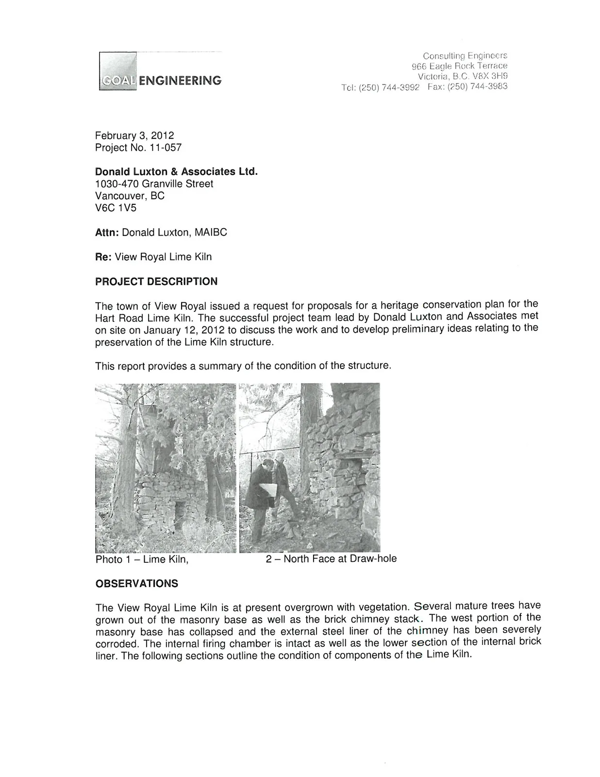
The View Royal Lime Kiln is at present overgrown with vegetation. Several mature trees have grown out of the masonry base as well as the brick chimney stack. The west portion of the masonry base has collapsed and the external steel liner of the chimney has been severely corroded. The internal firing chamber is intact as well as the lower section of the internal brick liner. The following sections outline the condition of components of the Lime Kiln.
A drawing has been created showing the approximate dimensions of the Lime Kiln elements. A project north has been selected for the northeast elevation as shown on the appended drawing. The cardinal directions referred to in this document are based on the project north direction.
RUBBLE MASONRY BASE
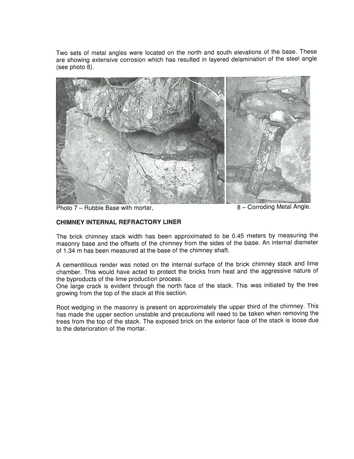
The rubble masonry base is in varied conditions on the structure. The exterior portion of the base has collapsed on the east and west elevations as shown in the photographs. The kiln base was constructed with a mortar between masonry units as shown in photograph 7. The majority of the joints between the units is void of mortar on the exterior. Extensive vegetation growth, root wedging and water runoff has likely washed out the exterior portions of the mortar of the base.
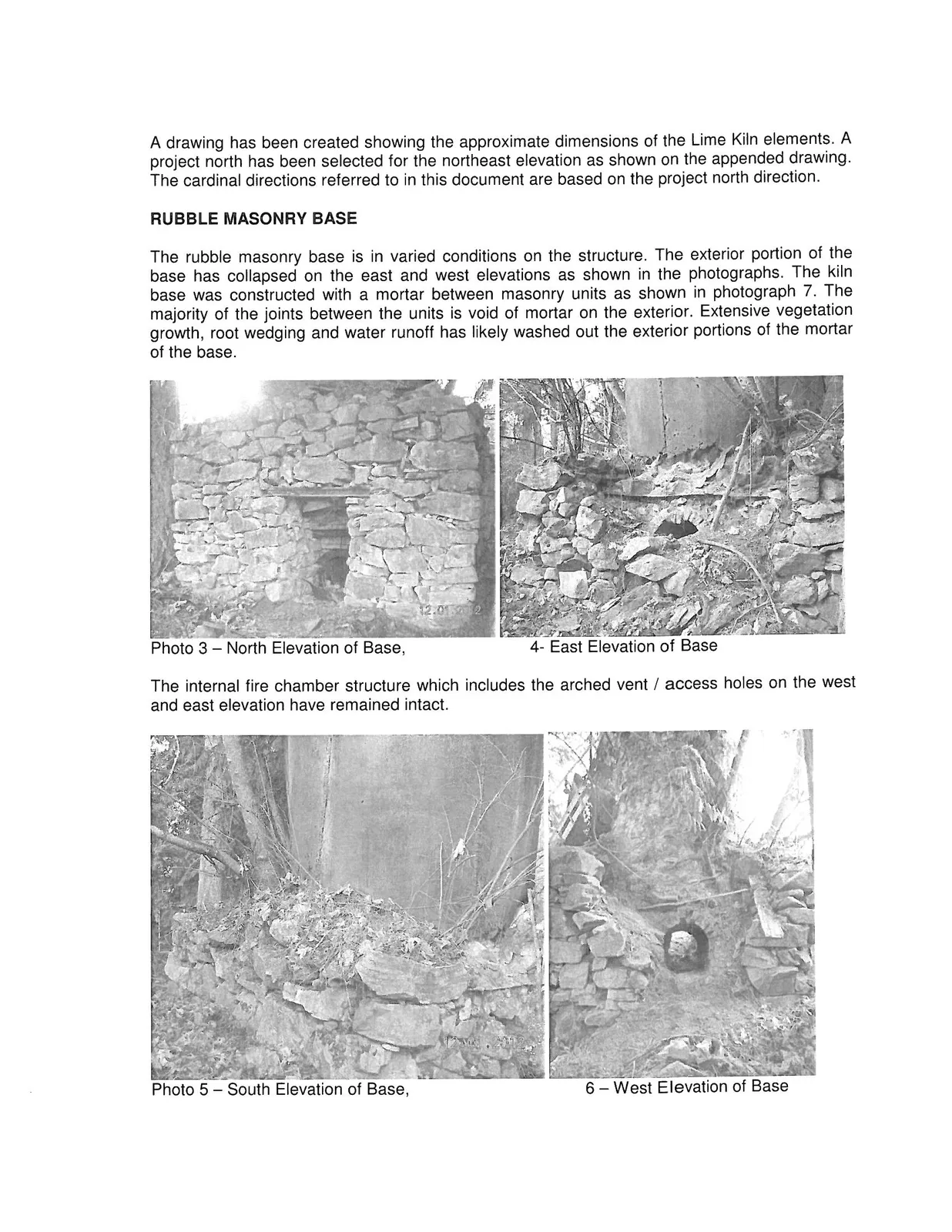
The internal fire chamber structure which includes the arched vent / access holes on the west and east elevation have remained intact.
Two sets of metal angles were located on the north and south elevations of the base. These are showing extensive corrosion which has resulted in layered delamination of the steel angle (see photo 8).
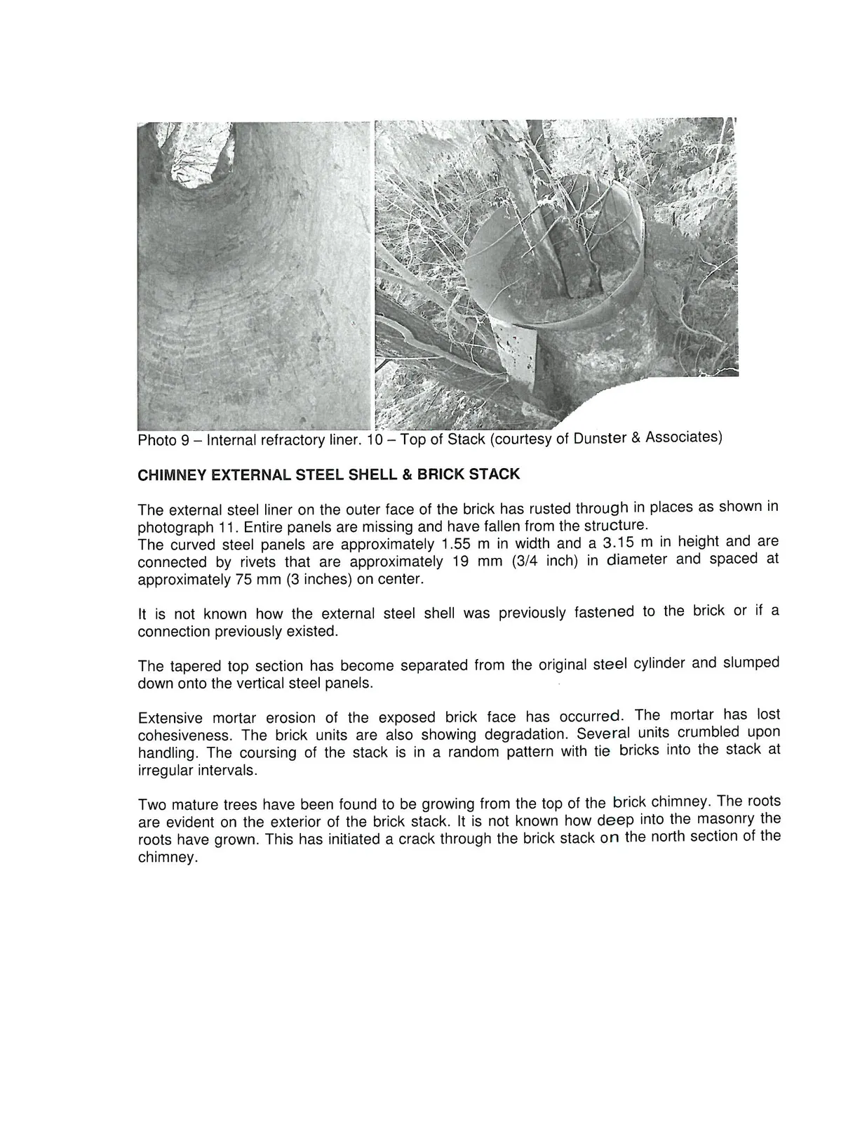
CHIMNEY INTERNAL REFRACTORY LINER
The brick chimney stack width has been approximated to be 0.45 meters by measuring the masonry base and the offsets of the chimney from the sides of the base. An internal diameter of 1.34 m has been measured at the base of the chimney shaft.
A cementitious render was noted on the internal surface of the brick chimney stack and lime chamber. This would have acted to protect the bricks from heat and the aggressive nature of the byproducts of the lime production process. One large crack is evident through the north face of the stack. This was initiated by the tree growing from the top of the stack at this section.
Root wedging in the masonry is present on approximately the upper third of the chimney. This has made the upper section unstable and precautions will need to be taken when removing the trees from the top of the stack. The exposed brick on the exterior face of the stack is loose due to the deterioration of the mortar.
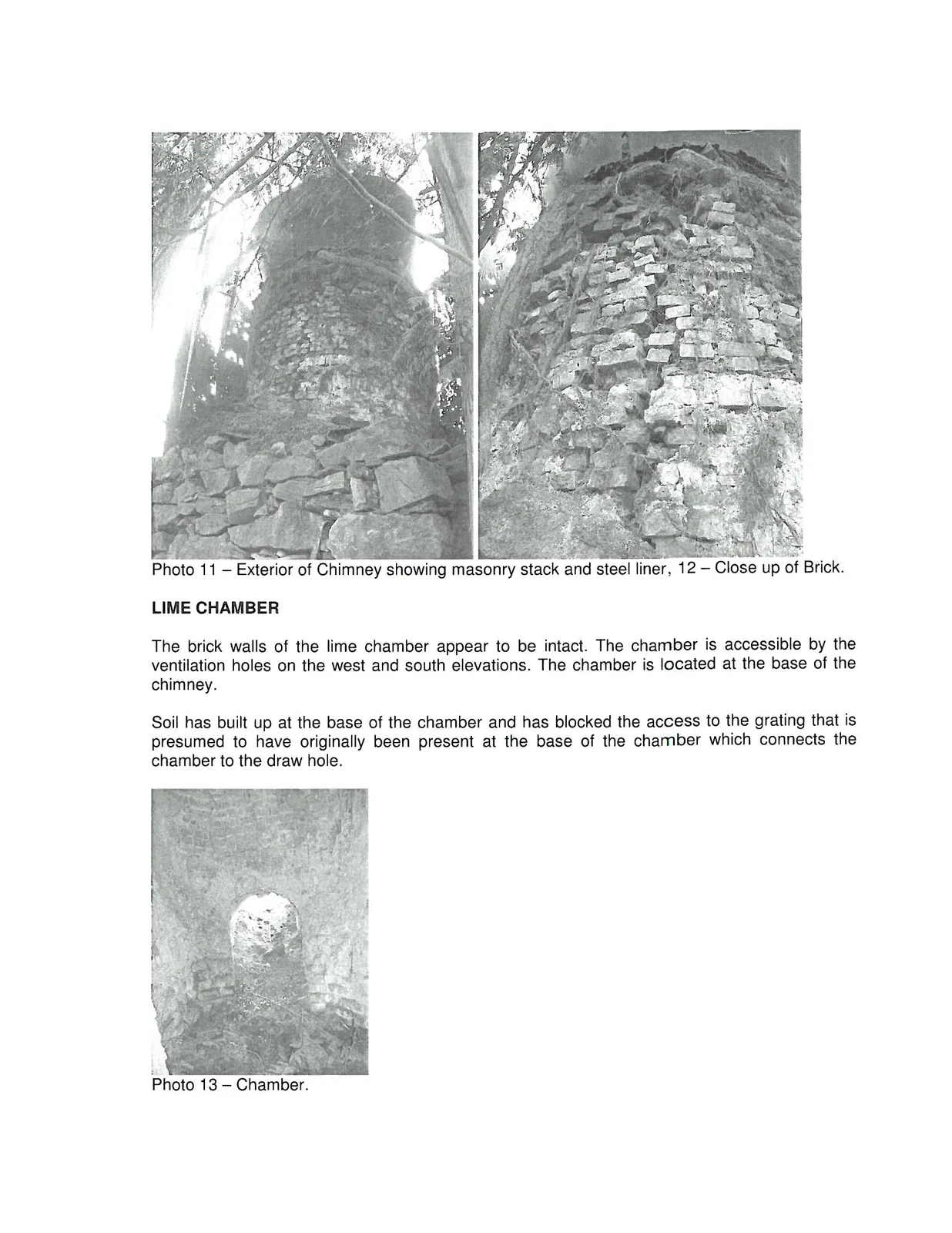
CHIMNEY EXTERNAL STEEL SHELL & BRICK STACK
The external steel liner on the outer face of the brick has rusted through in places as shown in photograph 11. Entire panels are missing and have fallen from the structure. The curved steel panels are approximately 1.55 m in width and a 3.15 m in height and are connected by rivets that are approximately 19 mm (3/4 inch) in diameter and spaced at approximately 75 mm (3 inches) on center.
It is not known how the external steel shell was previously fastened to the brick or if a connection previously existed.
The tapered top section has become separated from the original steel cylinder and slumped down onto the vertical steel panels.
Extensive mortar erosion of the exposed brick face has occurred. The mortar has lost cohesiveness. The brick units are also showing degradation. Several units crumbled upon handling. The coursing of the stack is in a random pattern with tie bricks into the stack at irregular intervals.
Two mature trees have been found to be growing from the top of the brick chimney. The roots are evident on the exterior of the brick stack. It is not known how deep into the masonry the roots have grown. This has initiated a crack through the brick stack on the north section of the chimney.
LIME CHAMBER
The brick walls of the lime chamber appear to be intact. The chamber is accessible by the ventilation holes on the west and south elevations. The chamber is located at the base of the chimney.
Soil has built up at the base of the chamber and has blocked the access to the grating that is presumed to have originally been present at the base of the chamber which connects the chamber to the draw hole.
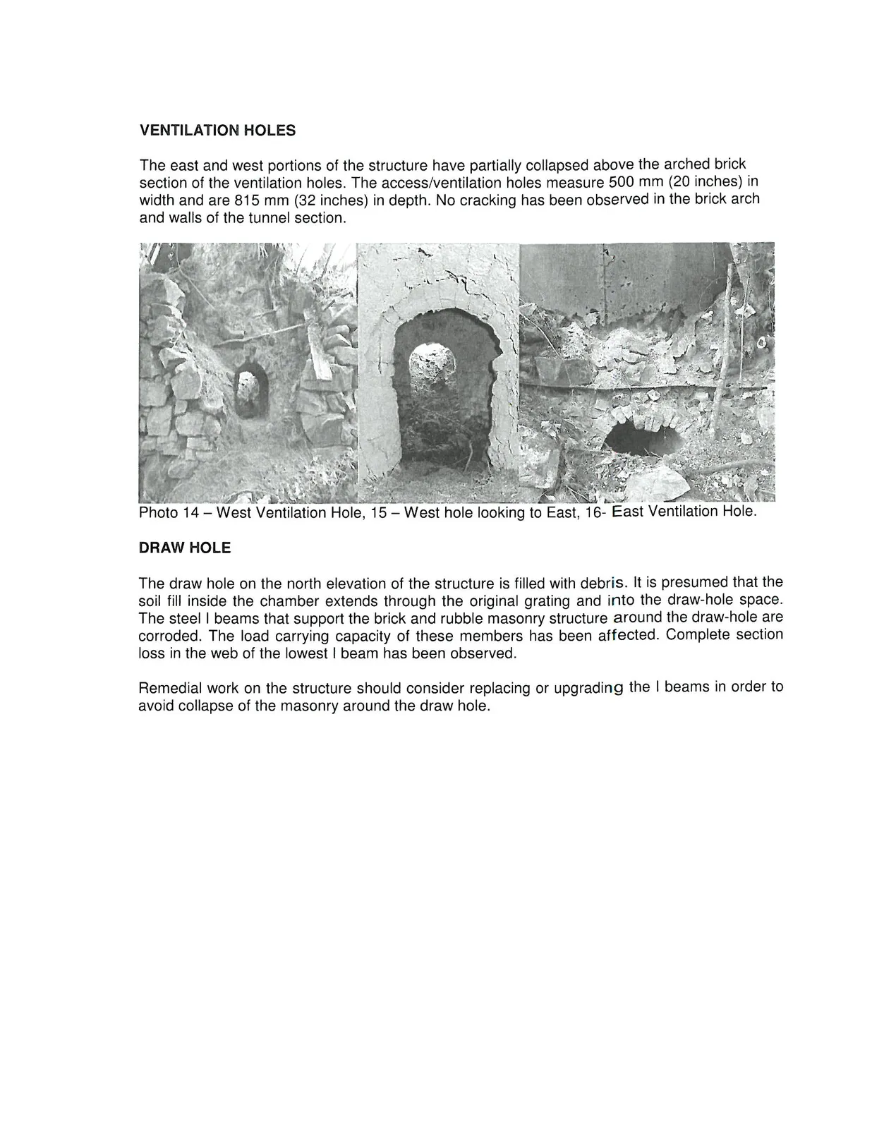
VENTILATION HOLES
The east and west portions of the structure have partially collapsed above the arched brick section of the ventilation holes. The access/ventilation holes measure 500 mm (20 inches) in width and are 815 mm (32 inches) in depth. No cracking has been observed in the brick arch and walls of the tunnel section.
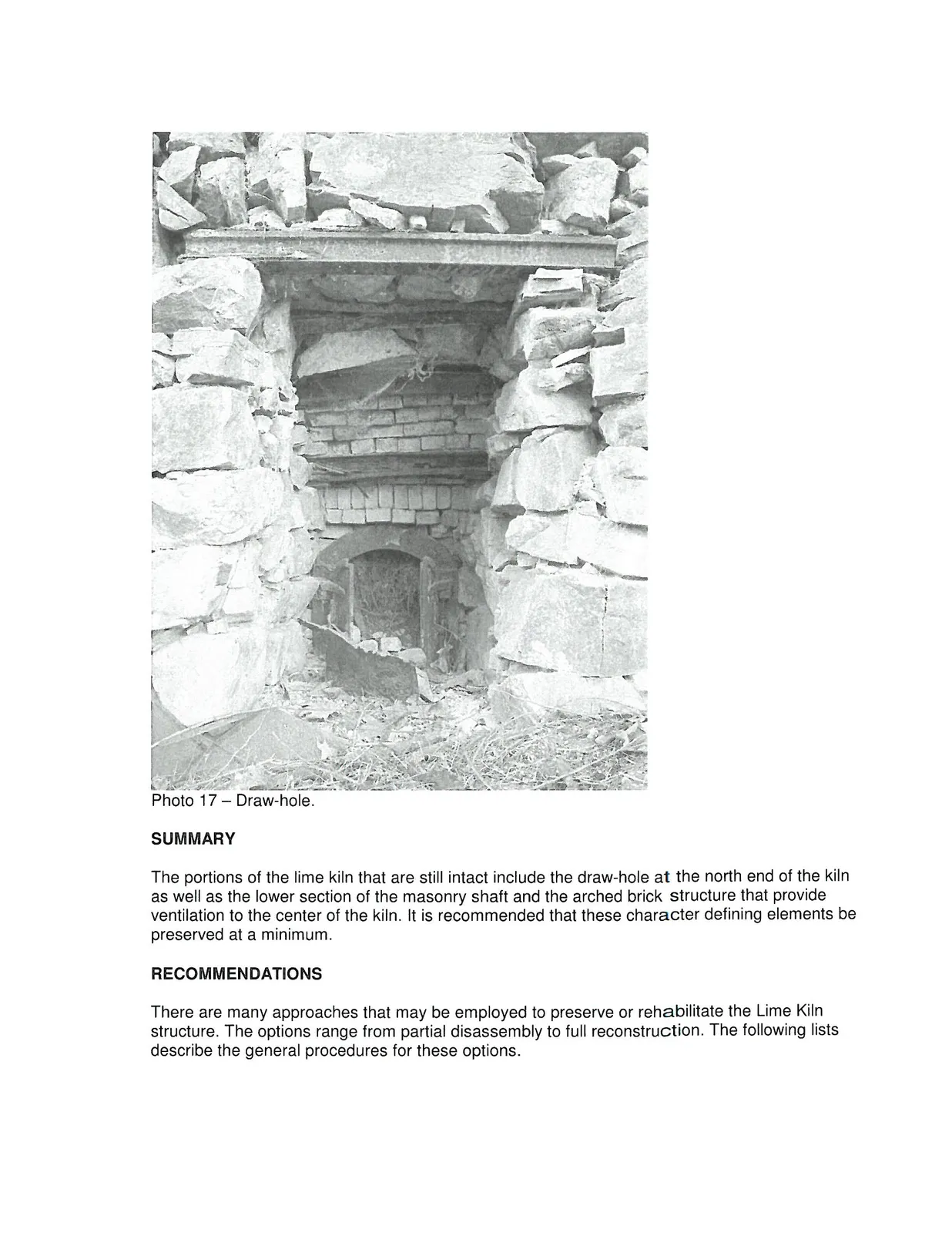
DRAW HOLE
The draw hole on the north elevation of the structure is filled with debris. It is presumed that the soil fill inside the chamber extends through the original grating and into the draw-hole space. The steel I beams that support the brick and rubble masonry structure around the draw-hole are corroded. The load carrying capacity of these members has been affected. Complete section loss in the web of the lowest I beam has been observed.
Remedial work on the structure should consider replacing or upgrading the I beams in order to avoid collapse of the masonry around the draw hole.
SUMMARY
The portions of the lime kiln that are still intact include the draw-hole at the north end of the kiln as well as the lower section of the masonry shaft and the arched brick structure that provide ventilation to the center of the kiln. It is recommended that these character defining elements be preserved at a minimum.
RECOMMENDATIONS
There are many approaches that may be employed to preserve or rehabilitate the Lime Kiln structure. The options range from partial disassembly to full reconstruction. The following lists describe the general procedures for these options.
Further investigative work would be required to identify the construction of the stack. At present the size and construction of the interior brick structure is unknown. The condition of the rubble base at depth is also not understood.
General (All Options)
- Remove trees and vegetation from brick chimney.
- Carefully disassembly of ~ 3/4 of brick stack.
- Remove steel shell from chimney exterior.
- Remove soil and vegetation from top of rubble base to expose stone units and mortar.
- Excavate soil from lime chamber.
- Remove organics from draw hole.
Option A - Disassembly
- Provide fencing to keep public away from structure at a safe distance.
Option B - Stabilization
- Partial rebuilding and re-pointing of stack.
- Reinforce load carrying capacity of steel members at draw hole. Replacement of structural steel members to be considered.
- Provide fencing to keep public away from structure at a safe distance.
Option C - Restoration
- Partial rebuilding and re-pointing of stack.
- Partial re-instatement of steel liner.
- Reinforce load carrying capacity of steel members at draw hole. Replacement of structural steel members to be considered.
- Upgrade arch support of ventilation holes at sides of chimney.
- Provide fencing to keep public away from structure at a safe distance.
Options which include re-building the stack with a steel liner supported on a steel frame should also be considered. This would require upgrading of the base to allow for anchorage of the steel frame.
The scope of the restoration work will depend on the design concept chosen for preservation of the Lime Kiln and site.
We trust this information is sufficient. Please call if you have any questions.
Sincerely,
Mark Byram, P.Eng. Materials Engineer
Greg Ovstaas, P.Eng. Senior Materials Engineer
Document Images
(1)