Appendix
Attachment 15 - Servicing Concept Diagram
March 13, 2018Page 721 section
Technical site plan overlaying the proposed utility and storm water management infrastructure.
Proposed 150 mm diameter water mainProposed detention gallery location
Servicing Concept
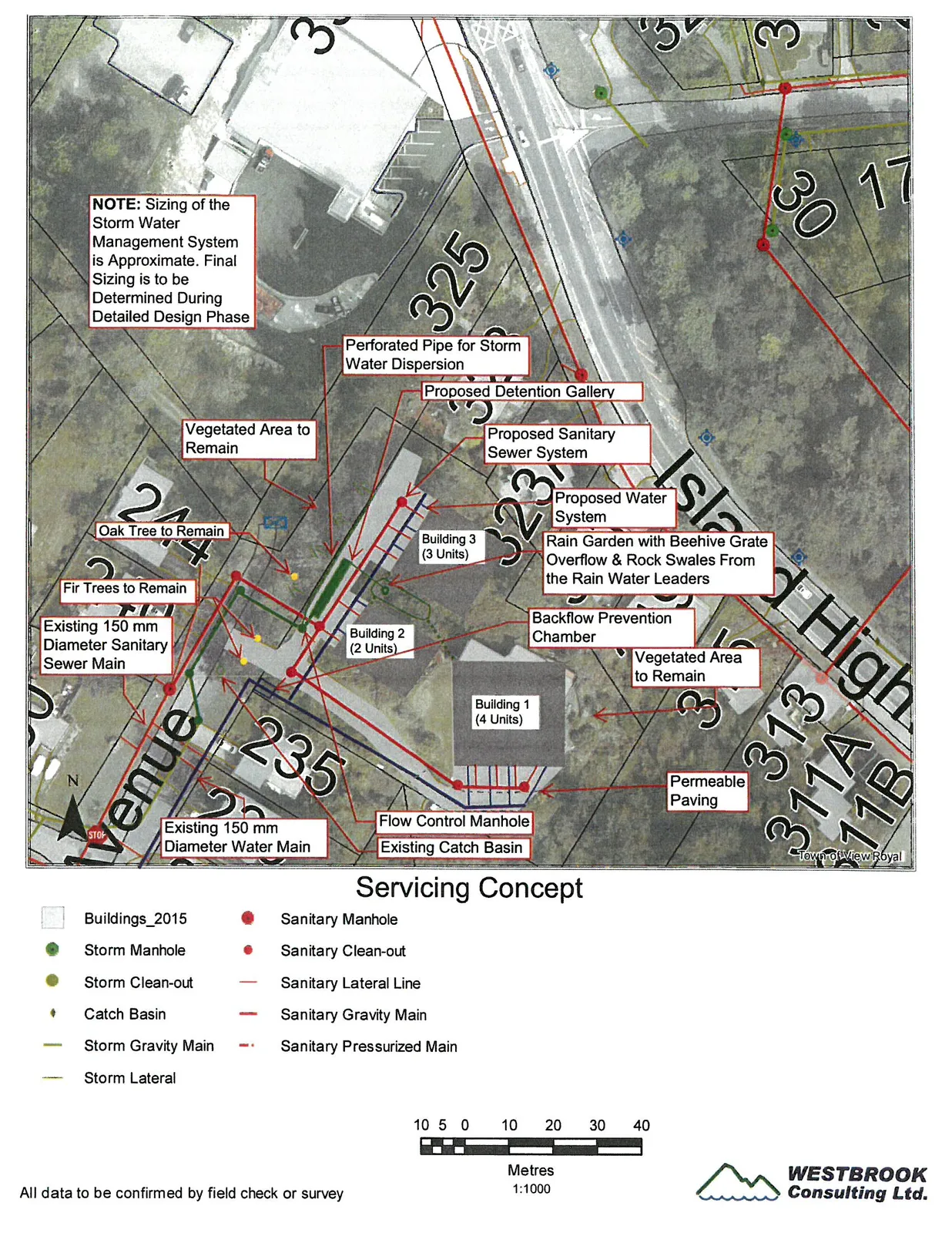
NOTE: Sizing of the Storm Water Management System is Approximate. Final Sizing is to be Determined During Detailed Design Phase
Map Labels and Callouts
- Perforated Pipe for Storm Water Dispersion
- Proposed Detention Gallery
- Proposed Sanitary Sewer System
- Proposed Water System
- Building 3 (3 Units)
- Building 2 (2 Units)
- Building 1 (4 Units)
- Rain Garden with Beehive Grate Overflow & Rock Swales From the Rain Water Leaders
- Backflow Prevention Chamber
- Vegetated Area to Remain
- Permeable Paving
- Flow Control Manhole
- Existing Catch Basin
- Oak Tree to Remain
- Fir Trees to Remain
- Existing 150 mm Diameter Sanitary Sewer Main
- Existing 150 mm Diameter Water Main
Legend
- Buildings_2015
- Storm Manhole
- Storm Clean-out
- Catch Basin
- Storm Gravity Main
- Storm Lateral
- Sanitary Manhole
- Sanitary Clean-out
- Sanitary Lateral Line
- Sanitary Gravity Main
- Sanitary Pressurized Main
All data to be confirmed by field check or survey.
Metres 1:1000 Scale: 10 5 0 10 20 30 40 Metres
Page 72
Extracted from: 2018 03 13 Committee of the Whole Agenda - Agenda - Pdf