This site is in beta — data may be incomplete and features are still being added.
Committee of the Whole/Documents/Site Plan Of Lot A Section 3 Highland District Plan VIP72045
Appendix

Site Plan Of Lot A Section 3 Highland District Plan VIP72045

September 13, 2016Pages 195–2035 sections

Series of technical drawings and photographs showing the proposed dwelling, dock location, and aerial site context.

2 APPROVAL OF AGENDA
Scale 1:200Includes Dock Elevation drawing and construction methodology photos

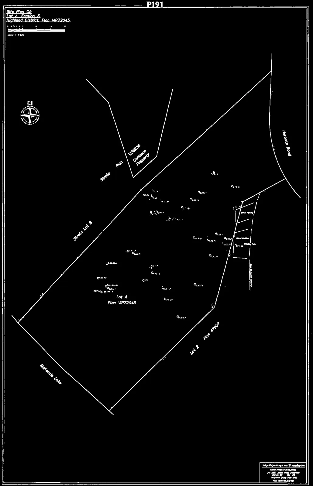
Site Plan - Lot A, Section 3

Site plan for Lot A, Section 3, Highland District, Plan VIP72045 showing property boundaries, elevations, and relationship to McKenzie Lake and Herbate Road
North arrow indicator

Project Identification

  • Site Plan Of: Lot A, Section 3, Highland District, Plan VIP72045
  • Address: 2670 Herbate Road
  • Scale: 1:200
  • Date: June 14, 2016
  • Surveyor: Wey Mayenburg Land Surveying Inc.

Notes

  • Distances and elevations shown are in metres.
  • Elevations are referenced to an assumed datum.
  • The subject property is affected by various registered documents including covenants and easements.

Page 195–203

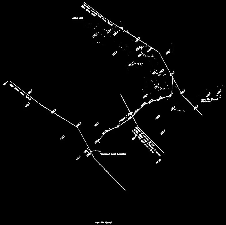
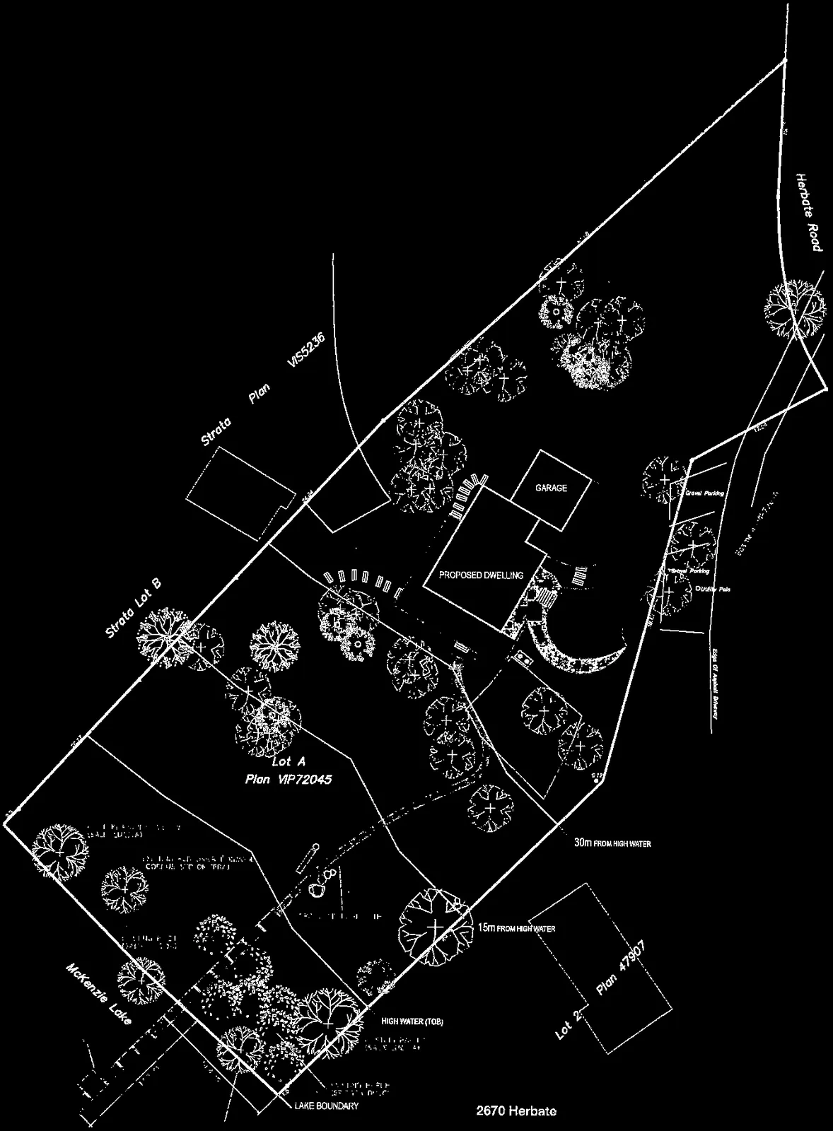
Dock Site Plan

Dock site plan showing locations for a proposed dwelling, garage, gravel parking, and the dock structure relative to the 15m and 30m high water setback lines

Location: 2670 Herbate Road

Key Map Features:

  • McKenzie Lake: Located along the southwest boundary.
  • Setbacks: 15m and 30m lines from high water are indicated.
  • Proposed Dwelling and Garage: Located in the central portion of Lot A.
  • Parking: Gravel parking area and "Oatley Path" identified near Herbate Road.
  • Dock Location: Proposed at the shoreline of McKenzie Lake.

Page 195–203

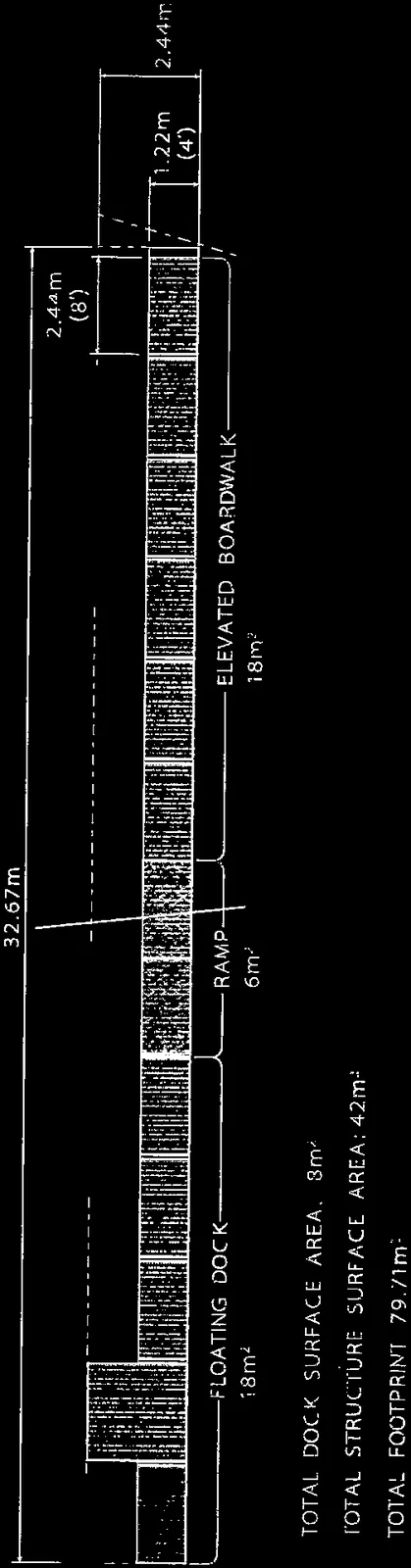
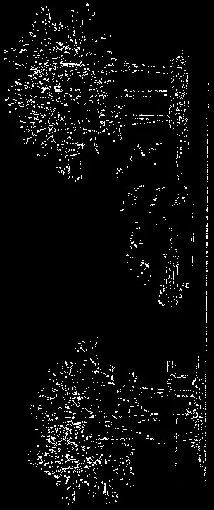
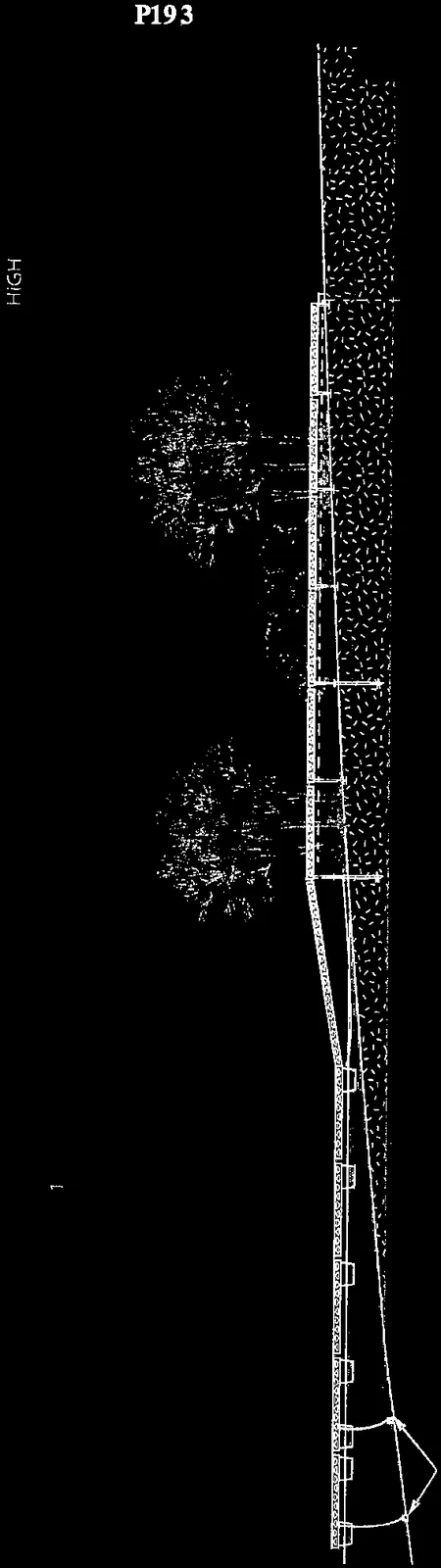
Dock Elevation and Plan

Side elevation view showing the dock structure's profile from the shoreline into the water
Plan view of the dock structure illustrating the layout of the elevated boardwalk, ramp, and floating dock sections
Cross-section rendering showing the dock structure relative to shoreline vegetation
Scale bar for the dock elevation and plan drawings (Scale 1:100)

Structure Specifications

  • Total Length: 32.67m
  • Elevated Boardwalk: 18m² area; 1.22m (4') width; composed of 2.44m (8') sections.
  • Ramp: 6m² area.
  • Floating Dock: 18m² area; 2.44m (8') width.
  • Anchoring: 4x Precast 150lb concrete anchors.

Area Summary

Feature Measurement
Total Dock Surface Area 18m²
Total Structure Surface Area 42m²
Total Footprint 79.1m²

Page 195–203

Dock Construction Details

The following photos illustrates the method of building the dock on site. The dock comes as a modular kit with components that are assembled on site.
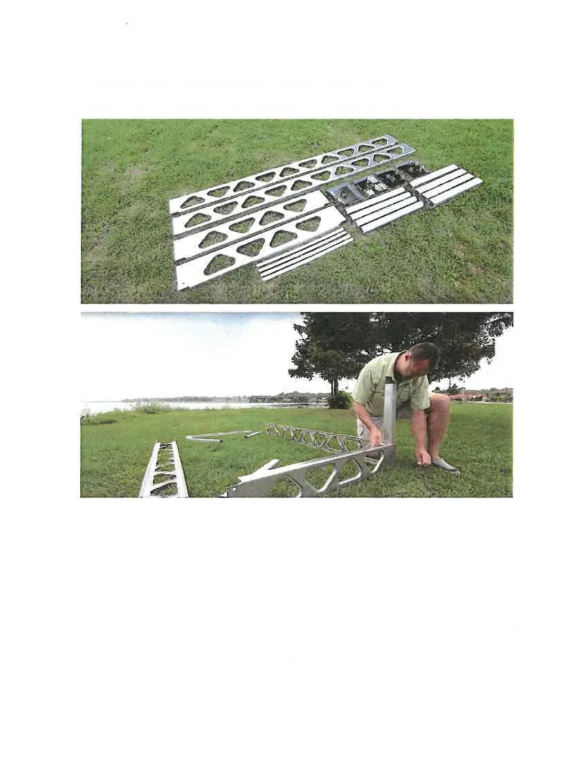
Two photos: Top photo shows the modular dock kit components laid out on grass; bottom photo shows a person assembling a metal frame segment.

The assembled modules are light enough to be positioned by hand without the use of cranes or heavy equipment.
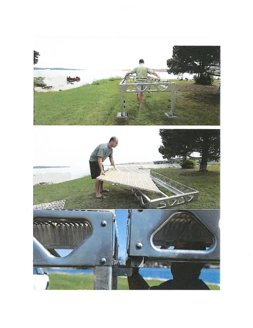
Three photos: Top photo shows a person moving an assembled metal frame; middle photo shows a person installing a deck panel; bottom photo provides a close-up detail of the metal frame connection.

4x8 Floating dock modules can be launched into the water by hand and attached to the other modules with stainless steel hardware.
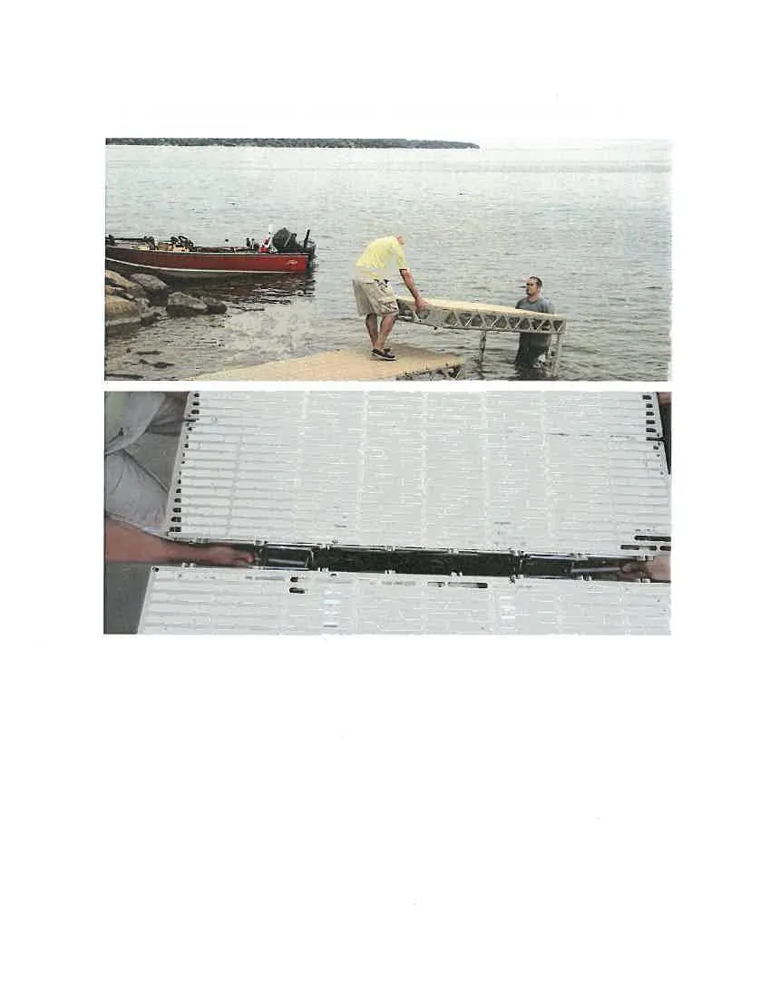
Two photos: Top photo shows two people launching a dock module into the water near a red boat; bottom photo is a close-up of the non-slip metal grating surface.

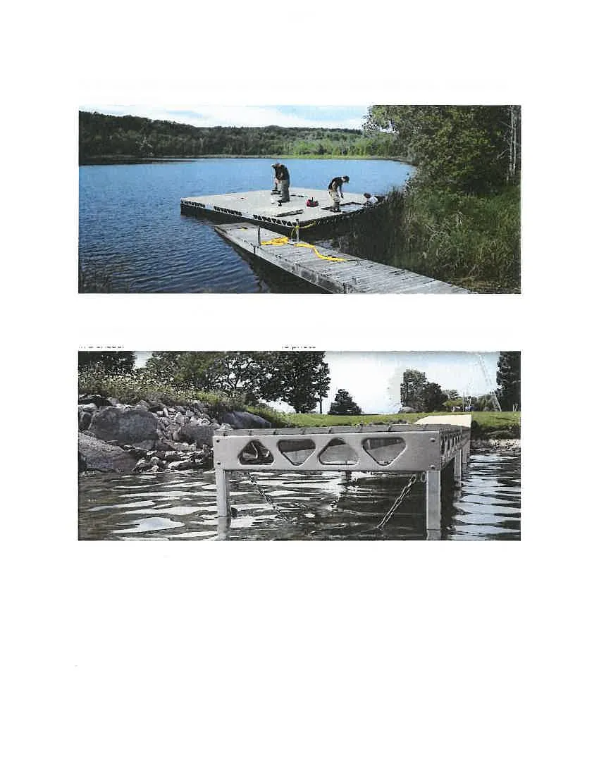
For the larger 8X8 module decking can be installed once the floating dock portion is launched into the water by hand.

[Image 17 (Top): Photo of two individuals installing decking on a floating dock module on the lake.]

The Floating dock is anchored in place with four 150lb precast concrete anchors attached to chains in a crisscross pattern. (Fixed dock shown in the photo)

[Image 17 (Bottom): Photo showing the dock frame in the water with diagonal anchor chains visible.]


Page 195–203

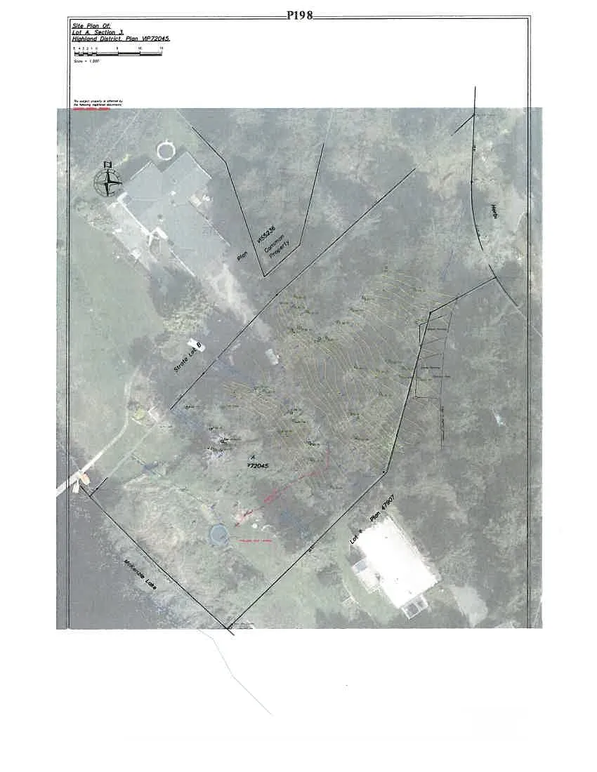
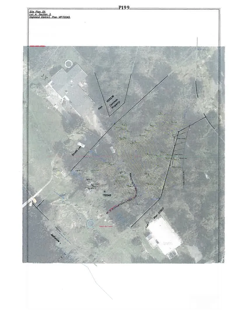
Aerial Overlays

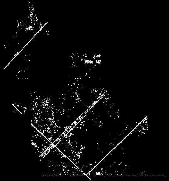
Aerial photograph of the subject property with site plan lines and topographical contours overlaid.
Aerial photograph overlay highlighting a trail path leading from the proposed development area to the dock site on McKenzie Lake.
Page 195–203

Document Images

(15)
Extracted from: 2016 09 13 Committee of the Whole Agenda