Technical Drawings and Attachments for 2 Watkiss Way
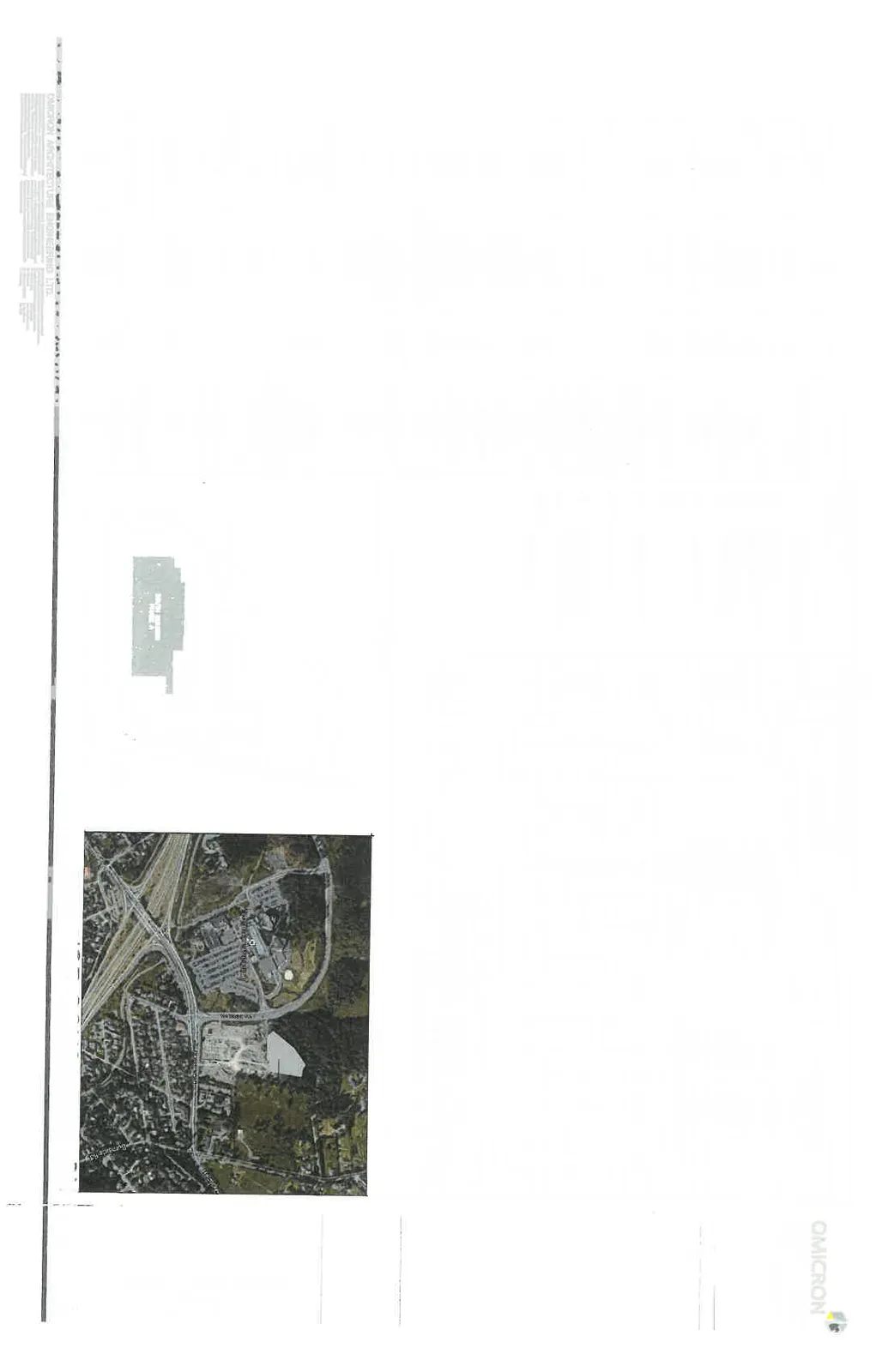
Comprehensive set of architectural drawings, floor plans, elevations, renderings, and site plans for the Phase 2 Eagle Creek Village development.
Report to Committee of the Whole Development Permit 2015/15 – 2 Watkiss Way Meeting Date: September 13, 2016
REVIEWED BY: L. Chase, MCIP, RPP, Director of Development Services
ATTACHMENTS:
- Property Location Map
- DP0.1 – Building Information – Omicron, July 20, 2016
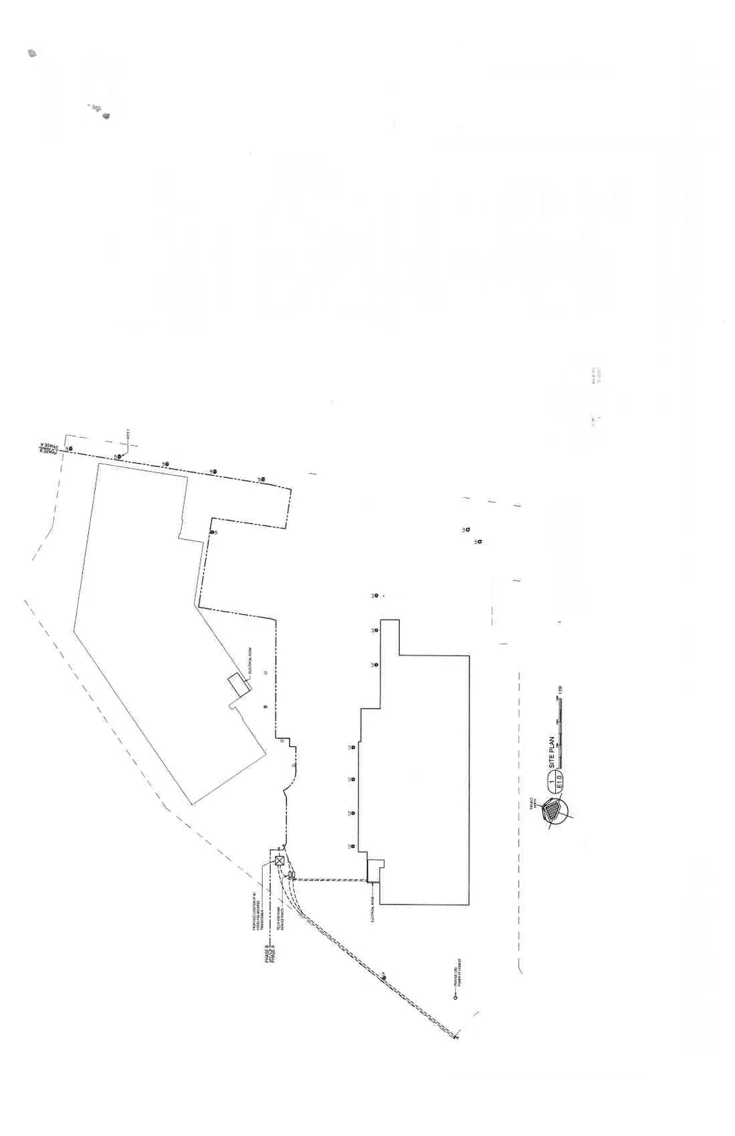
- DP1.0 – Site Plan – Omicron, July 20, 2016
- DP1.1 – Building Section and Site Details – Omicron, July 20, 2016
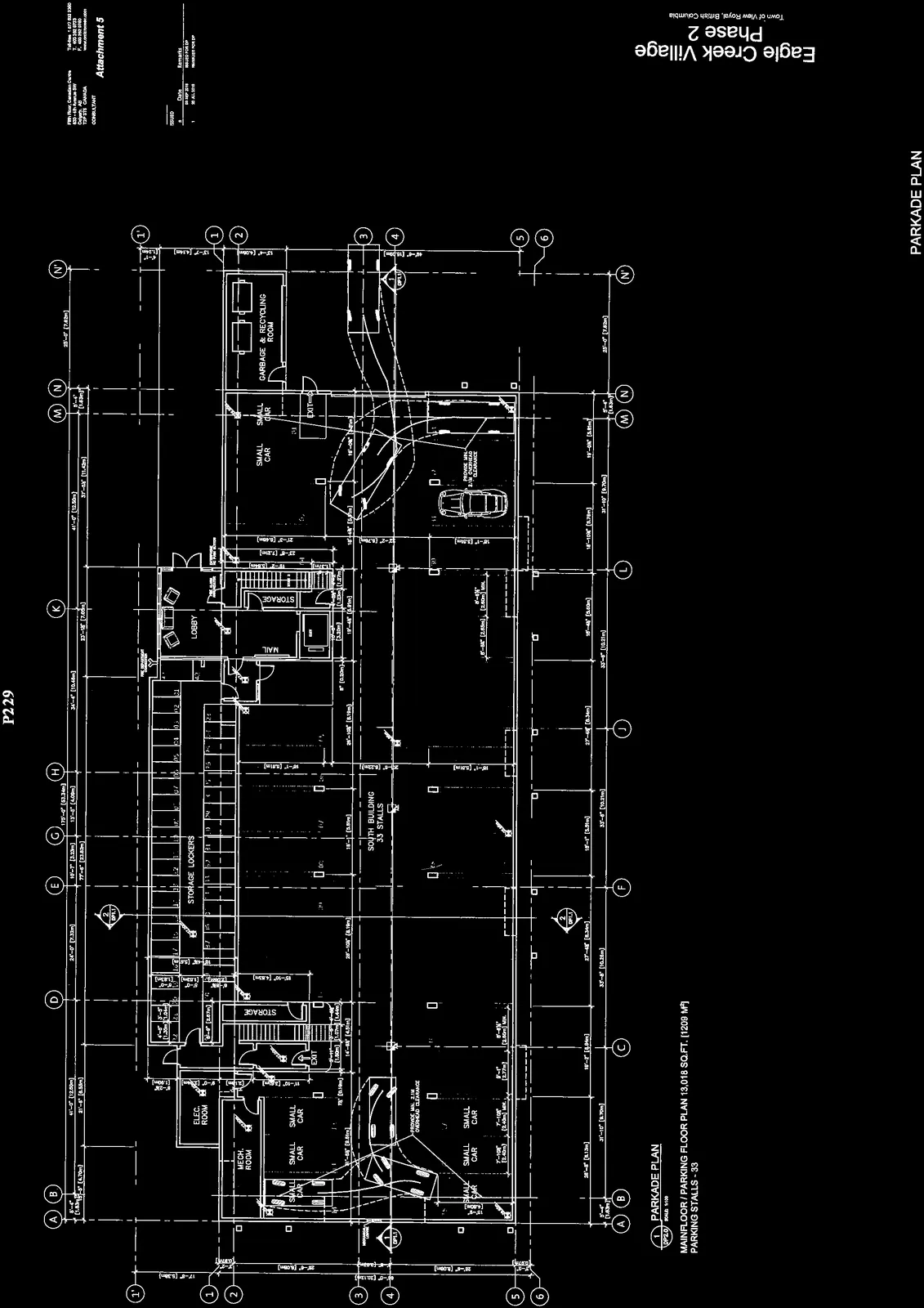
- DP2.0 – Parkade Plan – Omicron, July 20, 2016
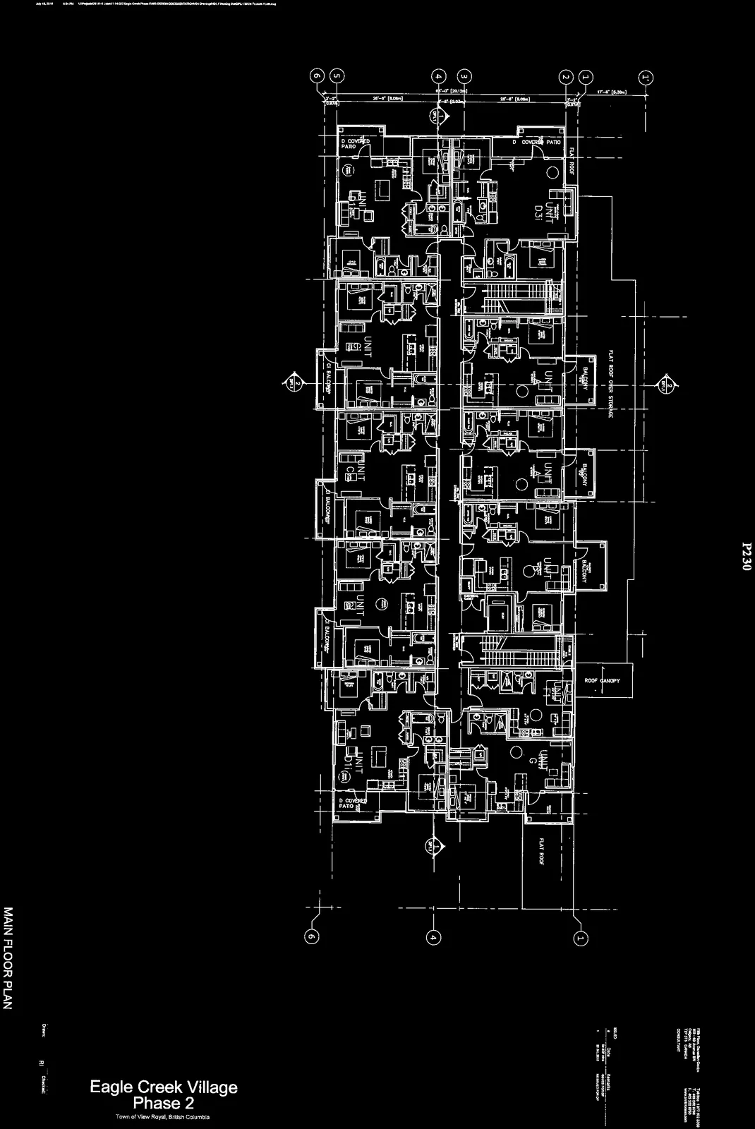
- DP2.1 – Main Floor Plan – Omicron, July 20, 2016
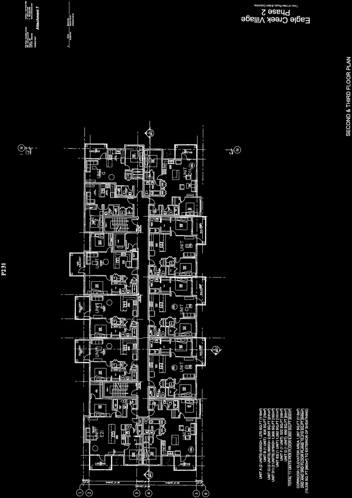
- DP2.2 – Second & Third Floor Plan – Omicron, July 20, 2016
- DP2.3 – Fourth Floor Plan – Omicron, July 20, 2016
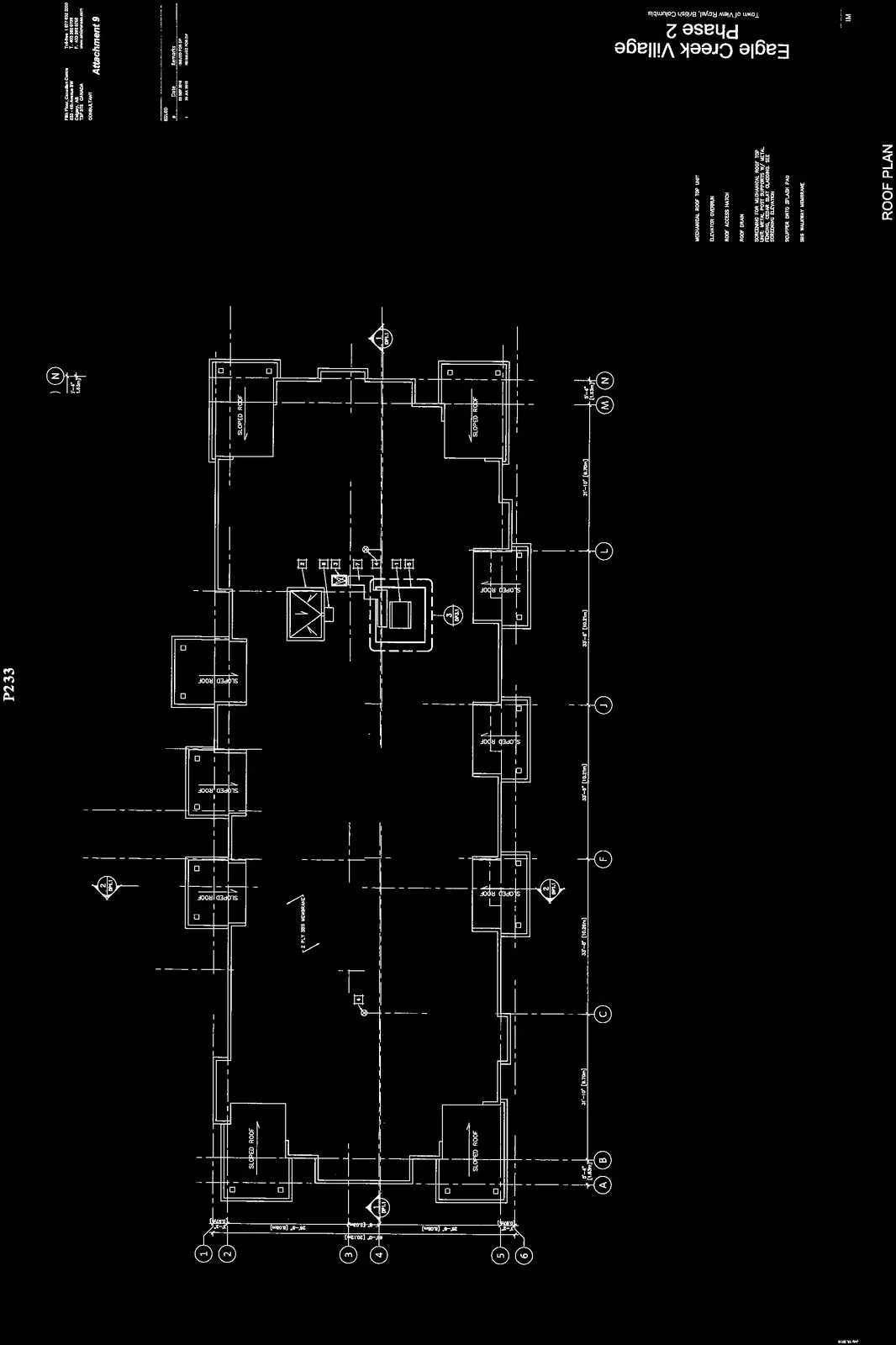
- DP2.4 – Roof Plan – Omicron, July 20, 2016
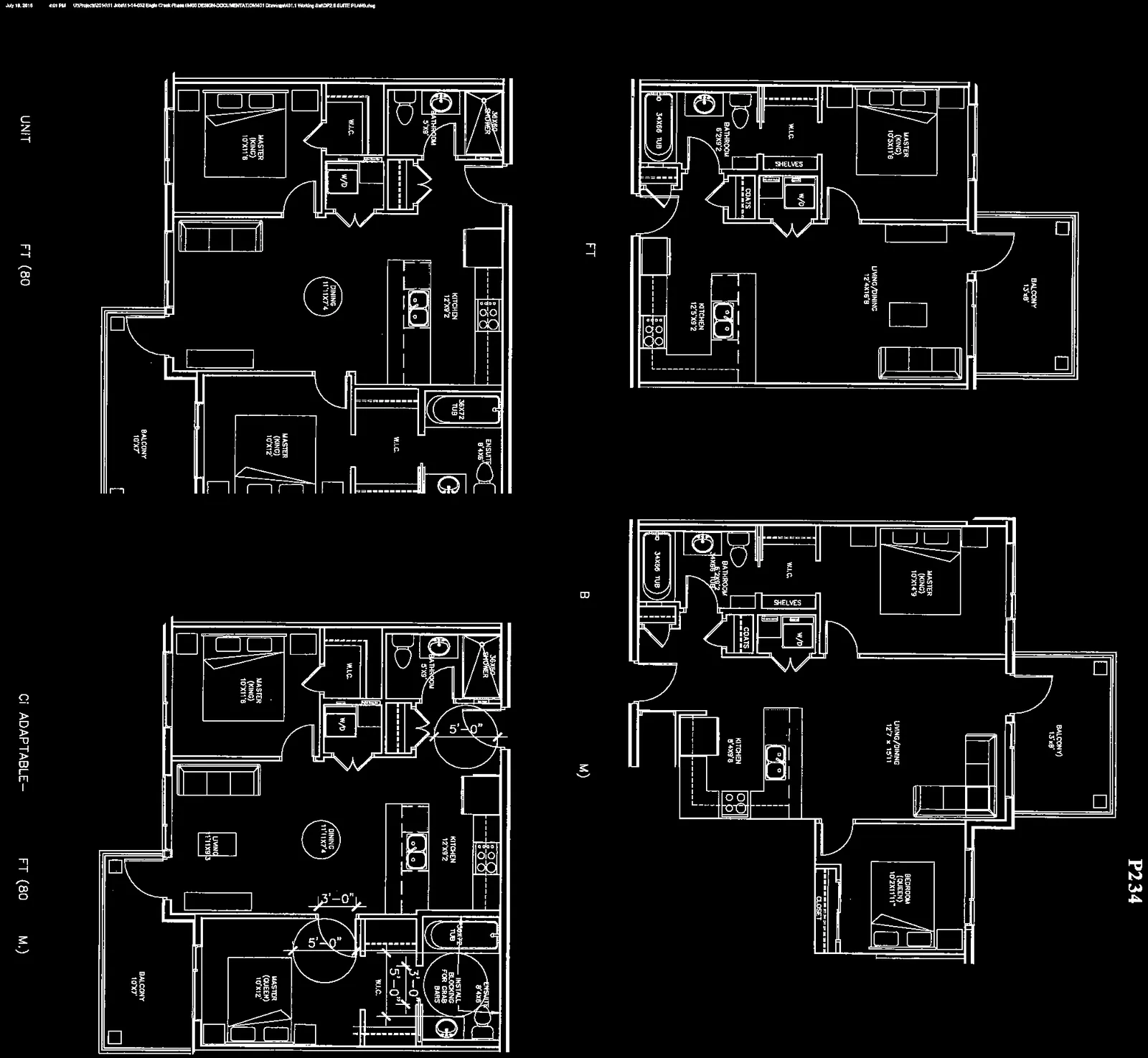
- DP2.5 – Large Scale Unit Plans – Omicron, July 20, 2016
- DP2.6 – Large Scale Units Plans – Omicron, July 20, 2016
- DP2.7 – Large Scale Unit Plans – Omicron, July 20, 2016
- DP3.1 – Exterior Elevations – Omicron, July 20, 2016
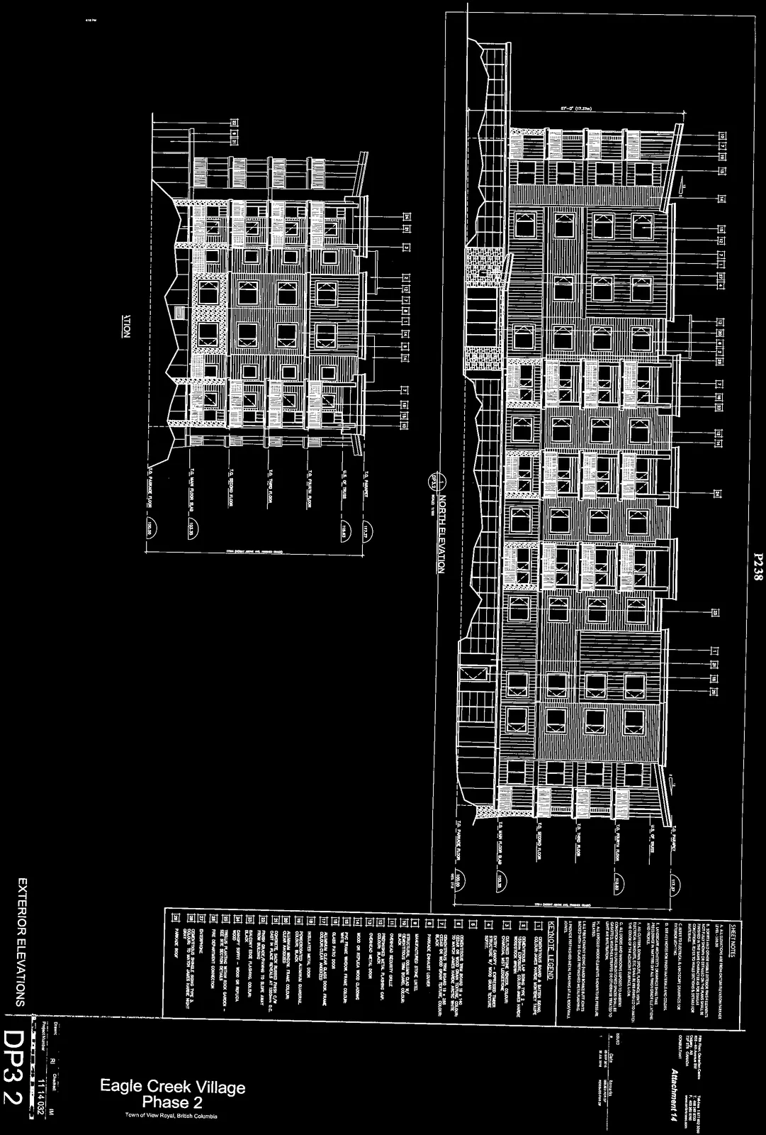
- DP3.2 – Exterior Elevations – Omicron, July 20, 2016
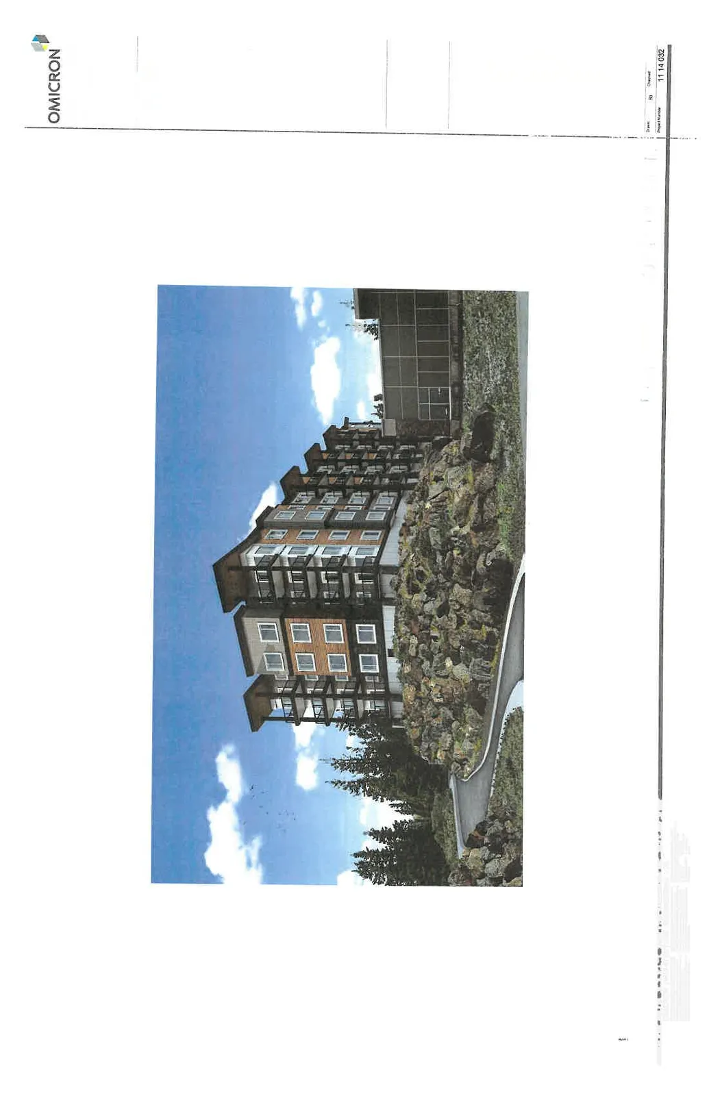
- DP4.1 – Rendering – Omicron, July 20, 2016
- DP4.2 – Rendering – Omicron, July 20, 2016
- DP4.3 – Rendering – Omicron, July 20, 2016
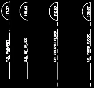
- SK-02 – Grade and Building Height Calculation – Omicron, July 20, 2016
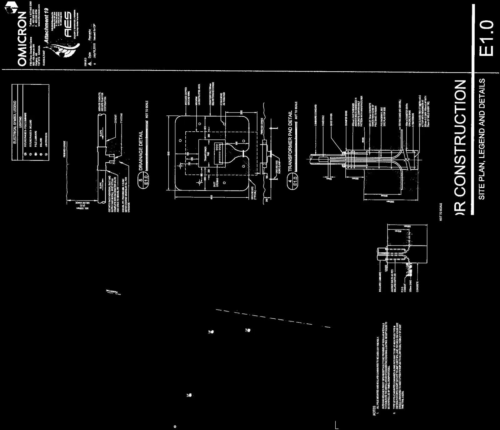
- E1.0 – Lighting Site Plan, Legend and Details – AES, July 18, 2016
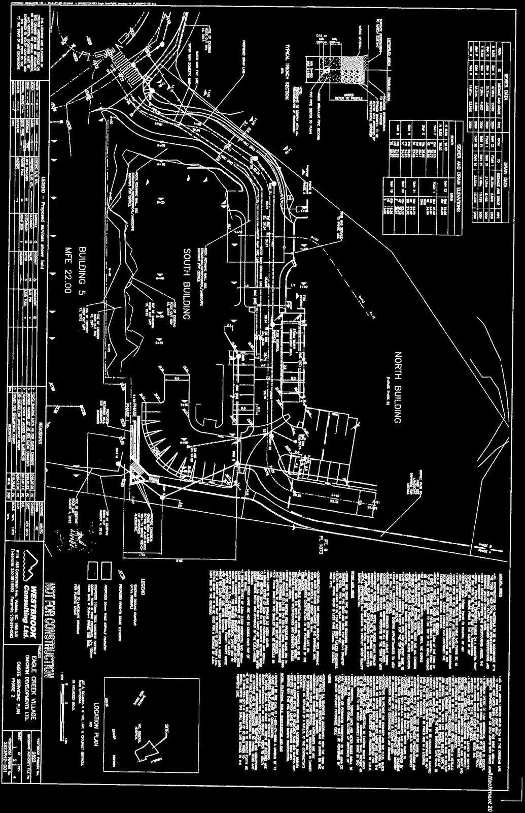
- Onsite Servicing Plan – Westbrook Consulting, July 8, 2016
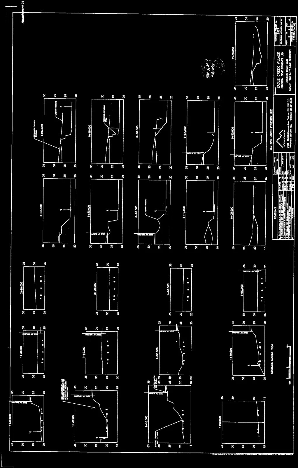
- Access Road and South Property Line Sections – Westbrook Consulting, July 8, 2016
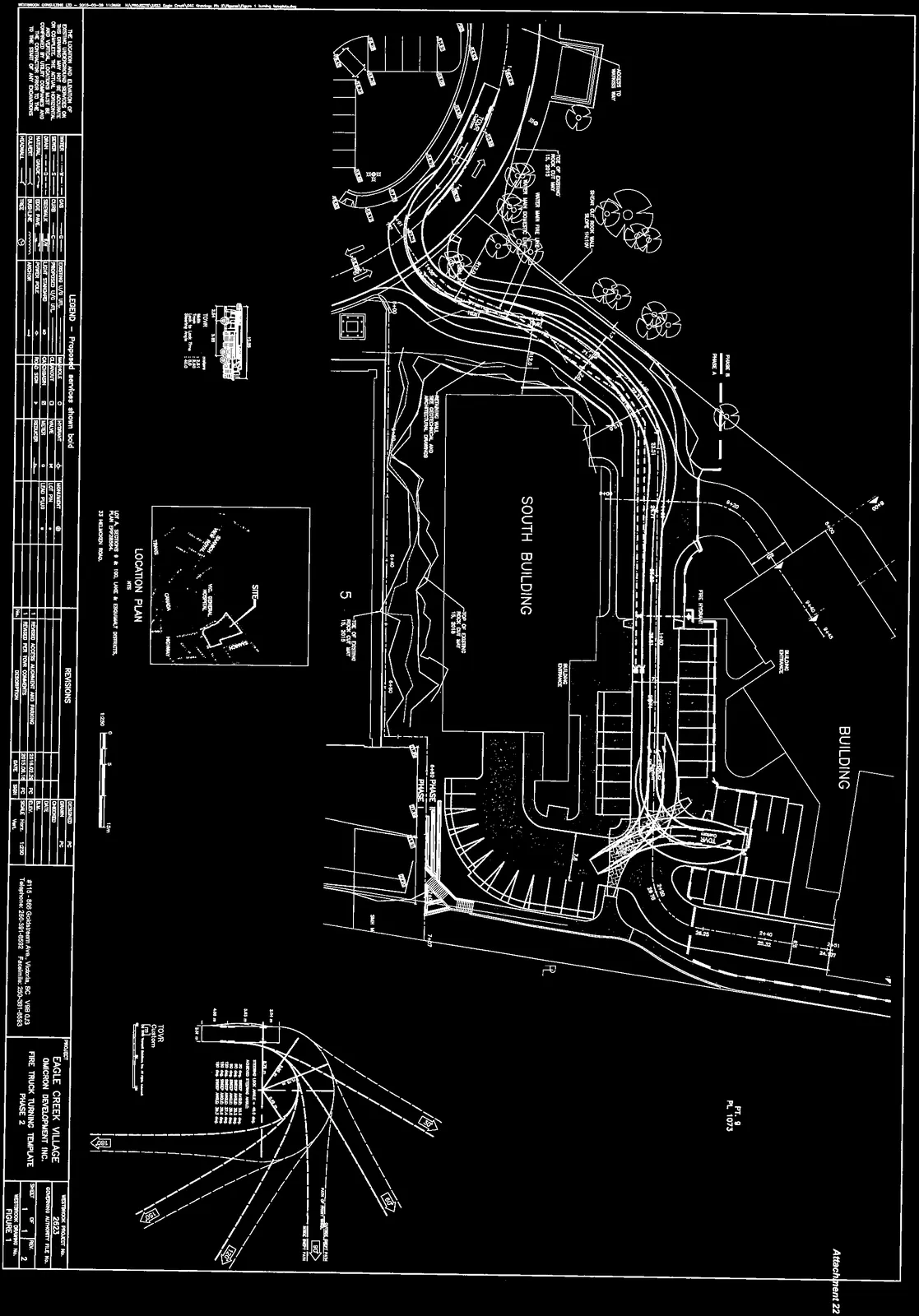
- Fire Truck Turning Template – Westbrook Consulting, July 8, 2016
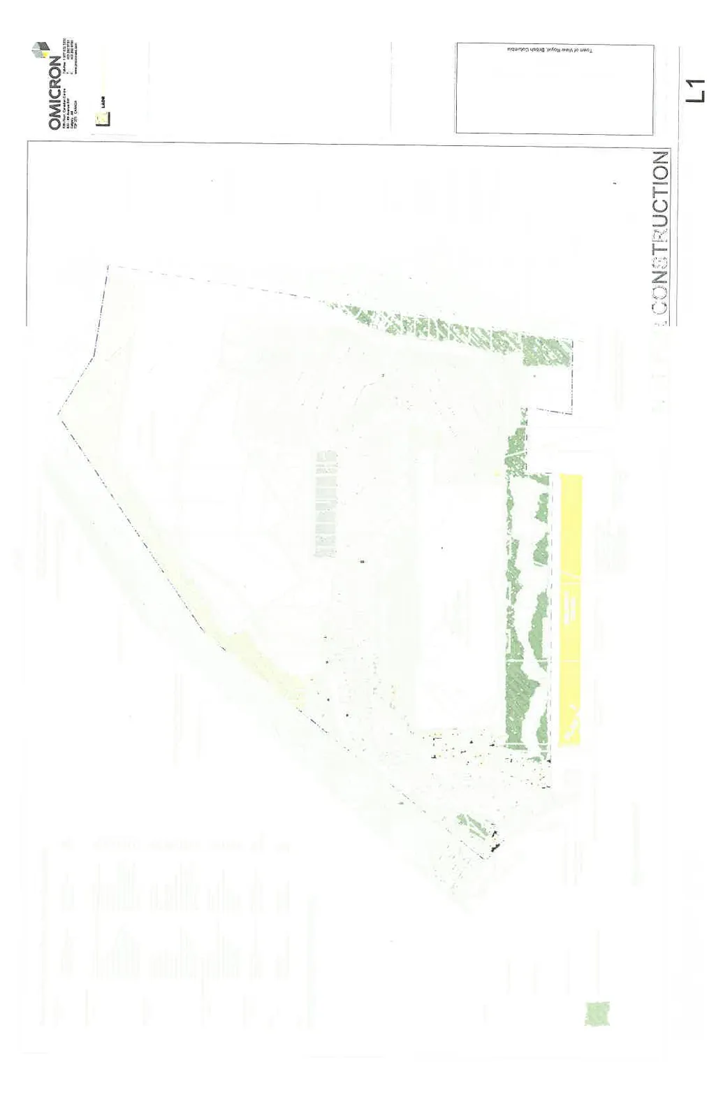
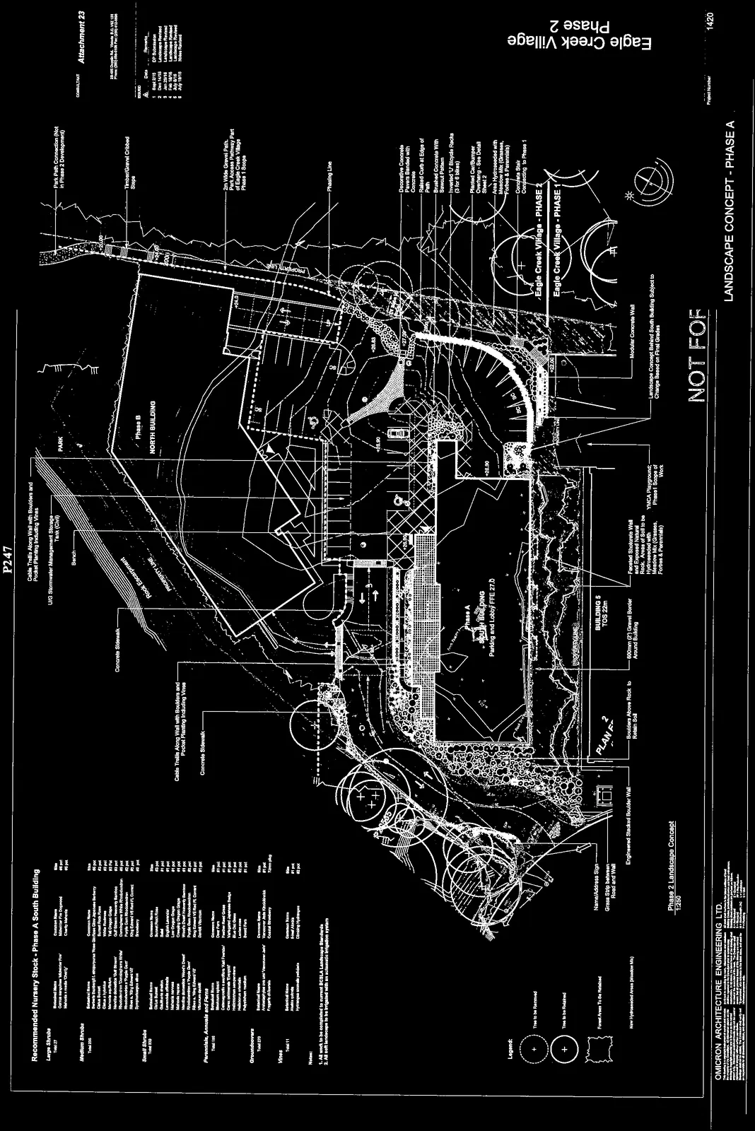
- L1 – Landscape Concept – LADR Landscape Architects, July 19, 2016
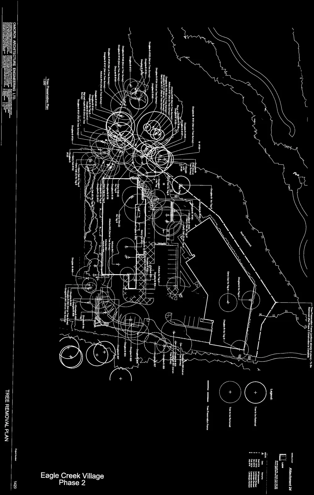
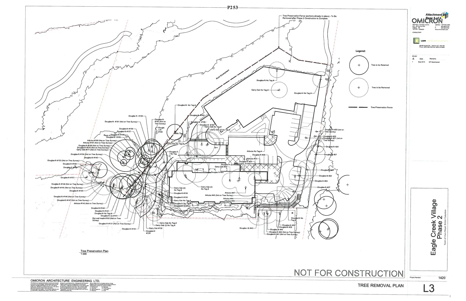
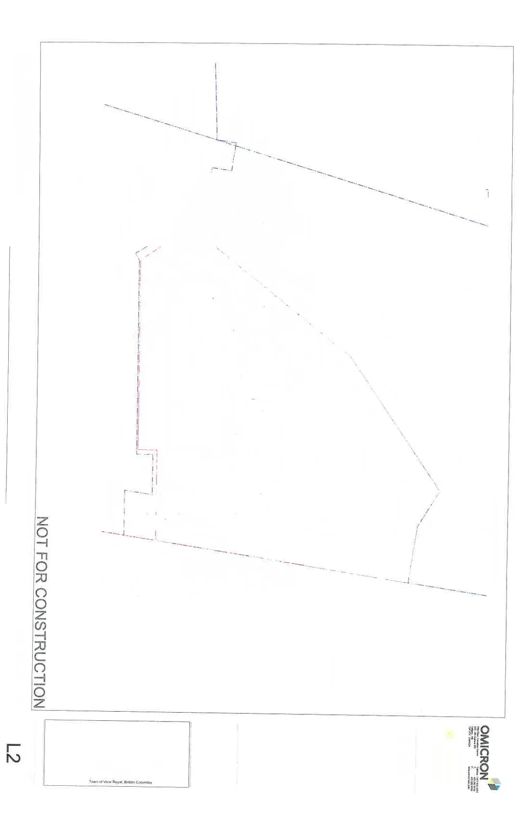
- L2 – Tree Removal Plan – LADR Landscape Architects, July 19, 2016
- Arborists Report – Talbot & Mackenzie & Associates, December 15, 2015 (6 pages)
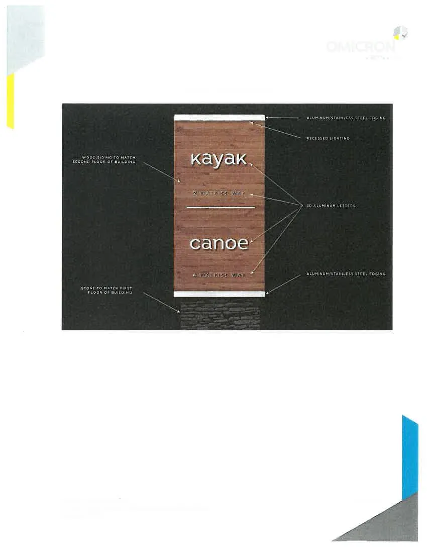
- Entry Signage Rendering 1 – Omicron, July 21, 2016
- Entry Signage Rendering 2 – Omicron, July 21, 2016
- Luminaire Example – Omicron, July 21, 2016
- Development Application Response Letter excerpt – Omicron, July 21, 2016 (5 pages)
- Project Sustainability Checklist excerpt (1 page)

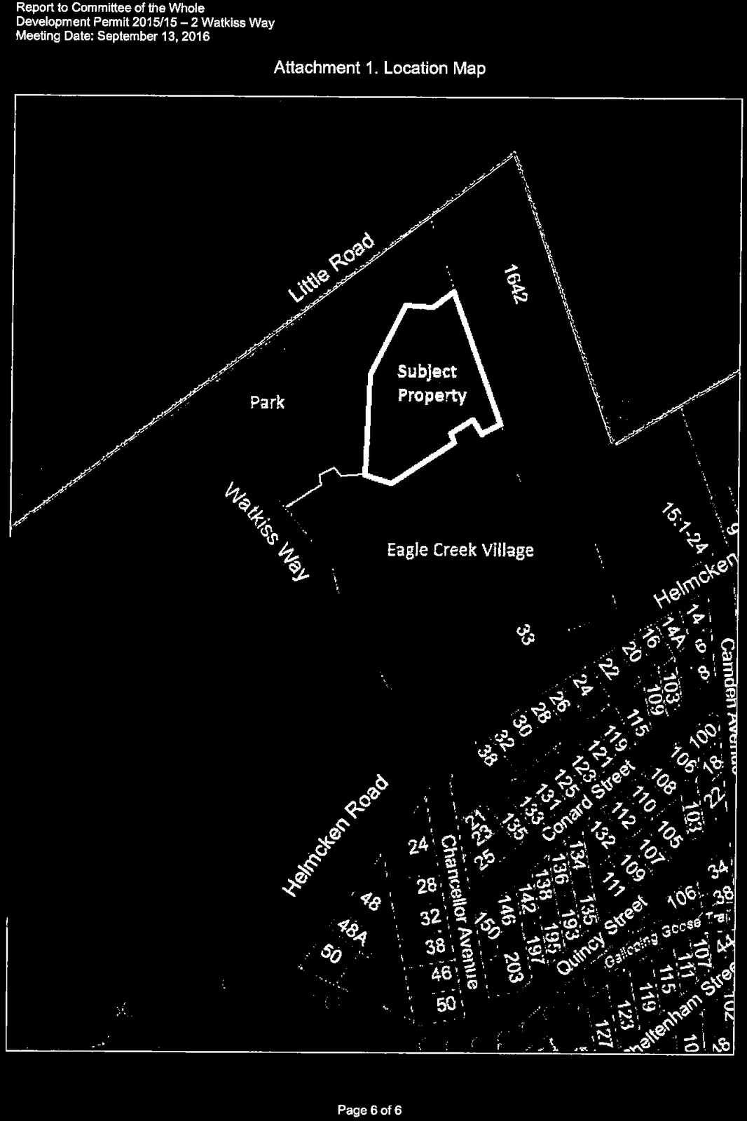
Attachment 1. Location Map
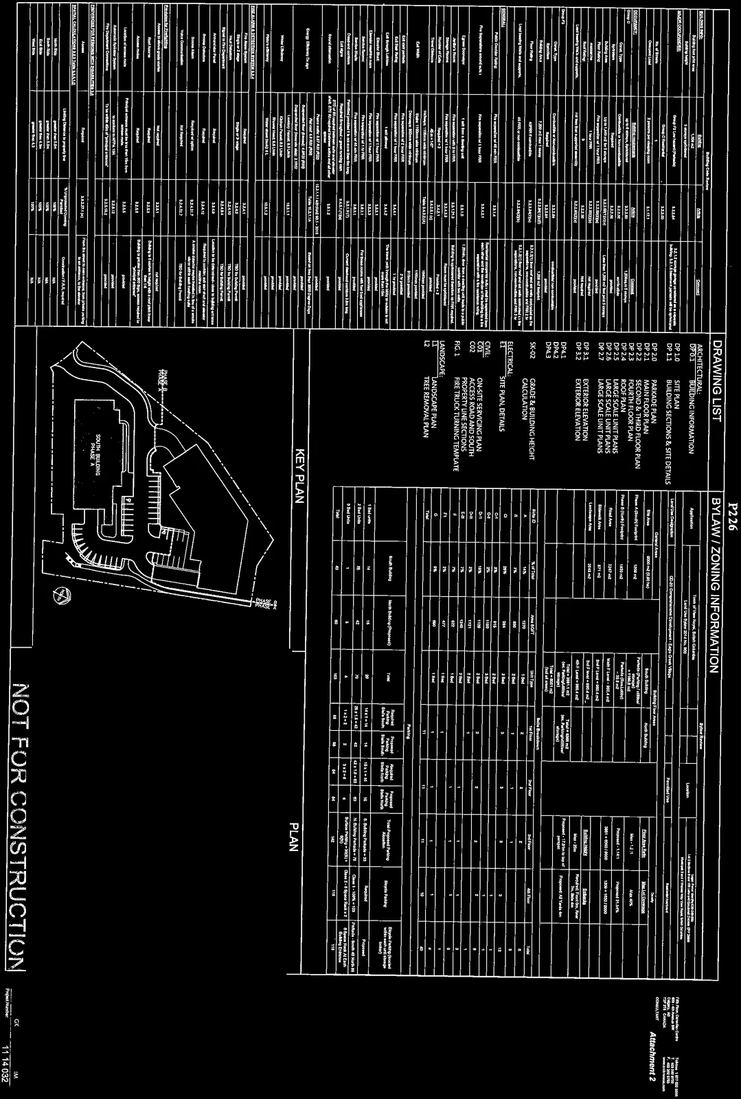
DP0.1 Building Information
BYLAW / ZONING INFORMATION
| Application | Town of View Royal, British Columbia | Location | Legal Parcel: Plan VIP54460 Lot A Sections 8 & 9 & 100, Lake & Esquimalt Districts, PID 024-544-245 |
|---|---|---|---|
| Land Use Designation | CD-22 Comprehensive Development - Eagle Creek Village | Permitted Use | Residential Multi-Family |
General Areas
- Site Area: 9000 m2 (0.90 ha)
- Phase A (South Building) Footprint: 1209 m2
- Phase B (North Building) Footprint: 1832 m2
- Road Area: 2247 m2
- Sidewalk Area: 671 m2
- Landscape Area: 3045 m2
Building Floor Areas
- South Building: 5938.8 m2
- North Building: [Proposed in future]
- Total = 5938.8 m2
Floor Area Ratio
- Max - 1.2 : 1
- Proposed - 1.14 : 1
- 3881 + 6350 / 9000
Max Lot Coverage
- Max 40%
- Proposed 31.54%
- 1209 + 1832 / 9000
Building Height
- Max - 23m
- Proposed - 17.91m to top of parapet
Setbacks
- Required: Front 3m, Rear 3m, Side 4.5m
- Proposed: All Yards 4m
Suite Breakdown
| Suite ID | % of Total | Area SQFT | Unit Type | 1st Floor | 2nd Floor | 3rd Floor | 4th Floor | Total |
|---|---|---|---|---|---|---|---|---|
| A | 14% | 1270 | 2 Bed | 2 | 2 | 2 | 6 | |
| B | 7% | 835 | 1 Bed | 1 | 1 | 1 | 3 | |
| Ci | 20% | 2595 | 2 Bed | 3 | 3 | 3 | 9 | |
| C-1 | 2% | 915 | 2 Bed | 1 | 1 | |||
| C-2 | 2% | 1190 | 2 Bed | 1 | 1 | |||
| D1i | 13% | 1958 | 2 Bed | 2 | 2 | 2 | 6 | |
| D1i-1 | 2% | 1121 | 2 Bed | 1 | 1 | |||
| D3i | 11% | 1062 | 2 Bed | 1 | 1 | 1 | 1 | 4 |
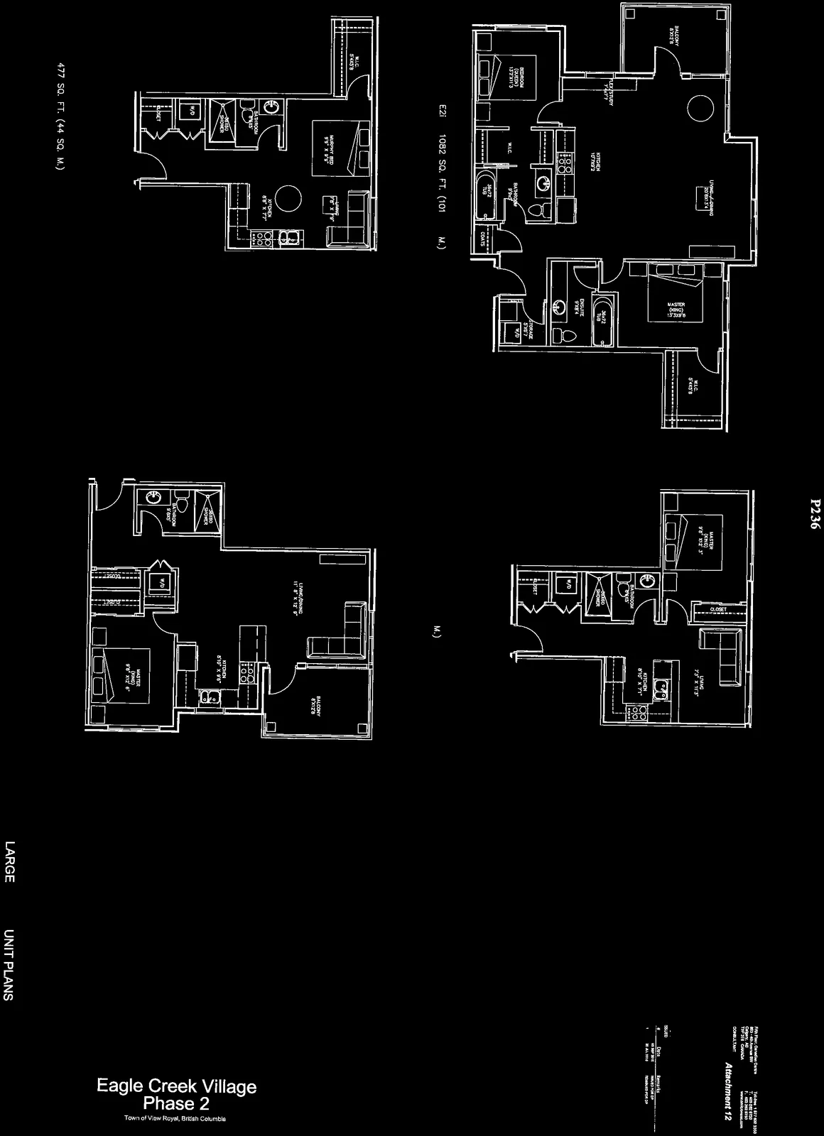
| E2i | 7% | 1082 | 2 Bed | 1 | 1 | 1 | 3 | |
| F | 2% | 522 | 1 Bed | 1 | 1 | 1 | 3 | |
| F1 | 5% | 477 | 1 Bed | 1 | 1 | 1 | 1 | 4 |
| G | 9% | 690 | 1 Bed | 1 | 1 | 1 | 1 | 4 |
| Total | 11 | 11 | 11 | 10 | 43 |
Parking
| Unit Type | South Building | North Building (Proposed) | Total | Required Parking South | Proposed Parking South | Required Parking North | Proposed Parking North | Total Proposed Parking | Bicycle Parking |
|---|---|---|---|---|---|---|---|---|---|
| 1 Bed units | 14 | 15 | 29 | 14 x 1 = 14 | 14 | 15 x 1 = 15 | 15 | S. Building Parkade = 33 | Required |
| 2 Bed units | 28 | 42 | 70 | 28 x 1.5 = 42 | 42 | 42 x 1.5 = 63 | 63 | N. Building Parkade = 73 | Class 1 - 100% = 103 |
| 3 Bed Units | 1 | 3 | 4 | 1 x 2 = 2 | 2 | 3 x 2 = 6 | 6 | Surface Parking = 36 (v) | Class 2 - 6 Space Rack x 2 |
| Total | 43 | 60 | 103 | 58 | 58 | 84 | 84 | 142 | 115 |
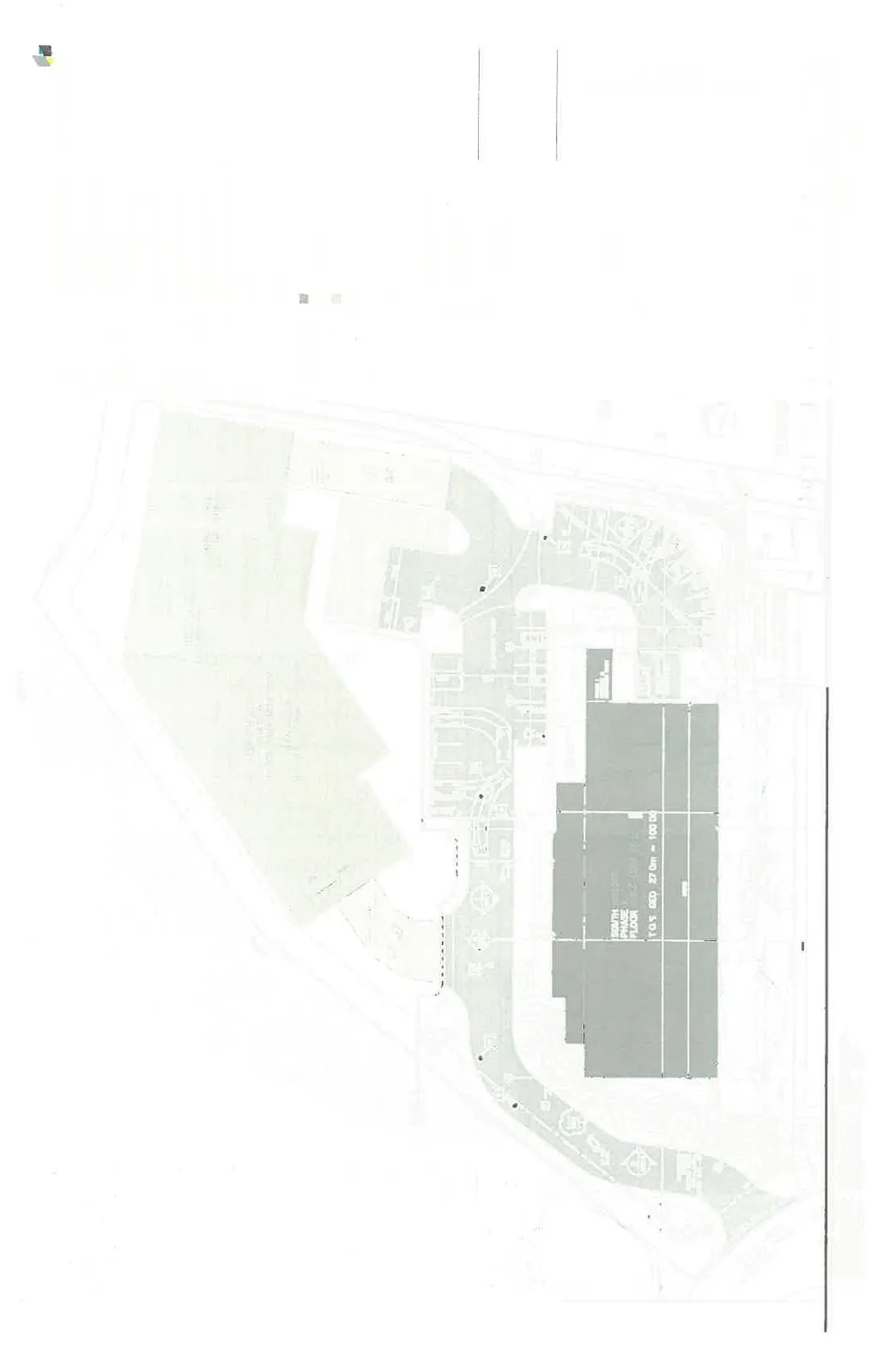
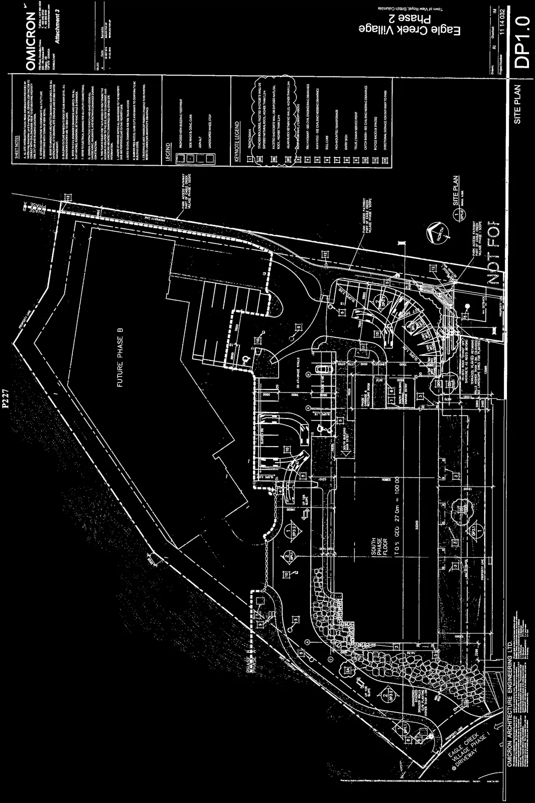
DP1.0 Site Plan
KEYNOTE LEGEND
- TRENCH DRAIN 2A. STACKED BOULDERS, FACETED SHOTCRETE WALL OR EXPOSED NATURAL ROCK, HIGHER THAN 1.2m 2B. ALLAN BLOCK RETAINING WALL, LOWER THAN 1.2m
- ROOF OVERHANG / CANOPY ABOVE
- FIRE HYDRANT - SEE CIVIL ENGINEERING DRAWINGS
- MAN HOLE - SEE CIVIL ENGINEERING DRAWINGS
- ROLL CURB
- PAD-MOUNTED TRANSFORMER
- ENTRY SIGN
- TRELLIS / SHAW SERVICE POINT
- CATCH BASIN - SEE CIVIL ENGINEERING DRAWINGS
- BICYCLE RACKS (6 SPACES)
- DIRECTIONAL SIGNAGE FOR PATHWAY TO PARK

DP1.1 Building Sections & Site Details

DP2.0 Parkade Plan

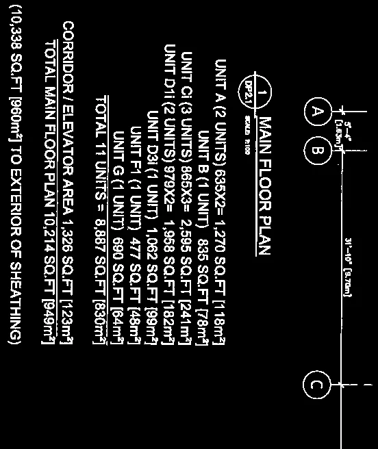
DP2.1 Main Floor Plan
Unit Breakdown:
- UNIT A (2 UNITS) 635X2 = 1,270 SQ.FT [118m2]
- UNIT B (1 UNIT) 835 SQ.FT [78m2]
- UNIT CI (3 UNITS) 865X3 = 2,595 SQ.FT [241m2]
- UNIT D1I (2 UNITS) 979X2 = 1,958 SQ.FT [182m2]
- UNIT D3I (1 UNIT) 1,062 SQ.FT [99m2]
- UNIT F1 (1 UNIT) 477 SQ.FT [48m2]
- UNIT G (1 UNIT) 690 SQ.FT [64m2]
- TOTAL 11 UNITS = 8,887 SQ.FT [830m2]
- CORRIDOR / ELEVATOR AREA 1,326 SQ.FT [123m2]
- TOTAL MAIN FLOOR PLAN 10,214 SQ.FT [949m2]
DP2.2 Second & Third Floor Plan

DP2.3 Fourth Floor Plan

DP2.4 Roof Plan
KEYNOTE LEGEND
- MECHANICAL ROOF TOP UNIT
- ELEVATOR OVERRUN
- ROOF ACCESS HATCH
- ROOF DRAIN
- SCREENING FOR MECHANICAL ROOF TOP UNIT, METAL POST SUPPORTS W/ METAL FENCING, CLEAR FLAT GLASSING SEE SCREENING ELEVATION
- SCUPPER ONTO SPLASH PAD
- SBS WALKWAY MEMBRANE
DP2.5 Large Scale Unit Plans
DP2.6 Large Scale Unit Plans
DP2.7 Large Scale Unit Plans

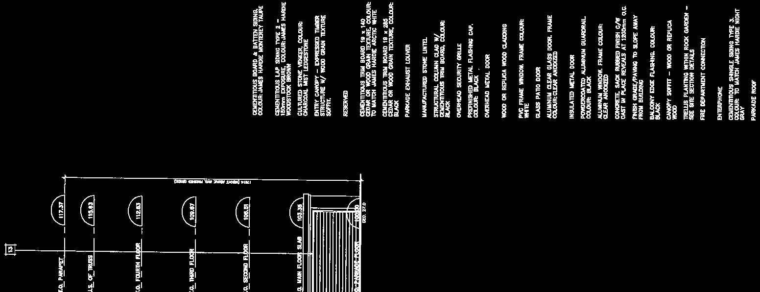
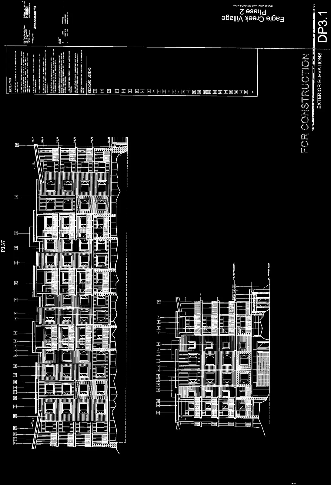
DP3.1 Exterior Elevations
KEYNOTE LEGEND (Summary of materials):
- CEMENTITIOUS BOARD & BATTEN SIDING. COLOUR: JAMES HARDIE MONTEREY TAUPE
- CEMENTITIOUS LAP SIDING TYPE 2 - 150mm EXPOSURE, COLOUR: JAMES HARDIE WOODSTOCK BROWN
- CULTURED STONE VENEER, COLOUR: CHARCOAL MIST LEDGESTONE
- ENTRY CANOPY - EXPRESSED TIMBER STRUCTURE W/ WOOD GRAIN TEXTURE SOFFIT.
- MANUFACTURED STONE LINTEL
- OVERHEAD SECURITY GRILLE
- WOOD OR REPLICA WOOD CLADDING
- PVC FRAME WINDOW. FRAME COLOUR: WHITE
- GLASS PATIO DOOR

DP3.2 Exterior Elevations
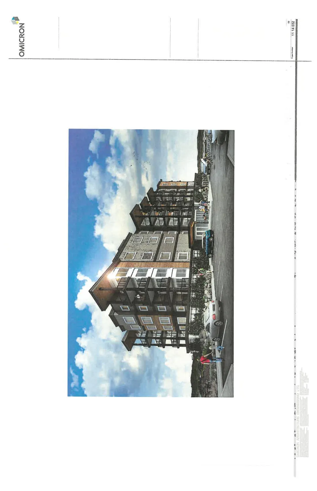
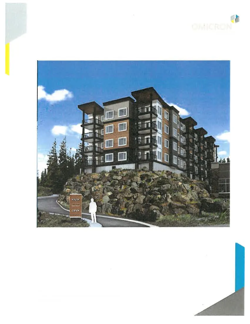
DP4.1, DP4.2, DP4.3 Renderings

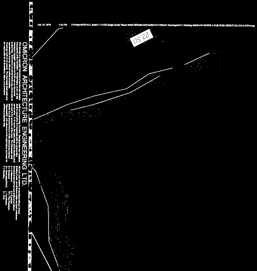
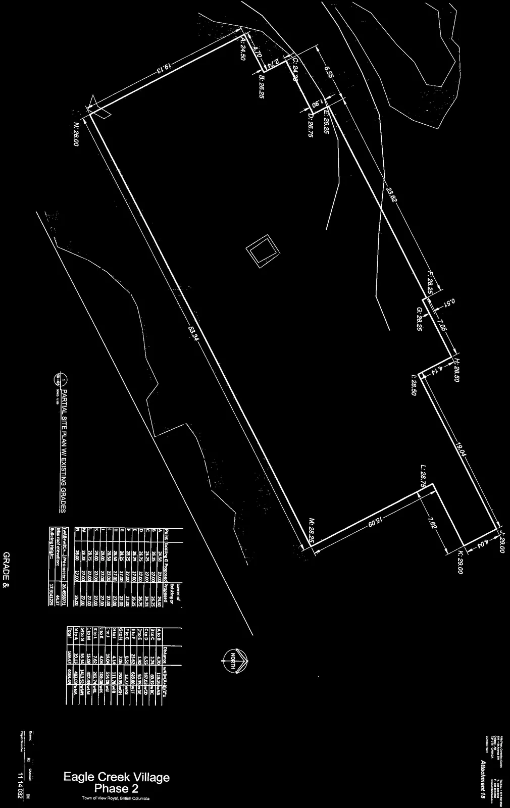
SK-02 Grade and Building Height Calculation
| Point | Existing G | Proposed | Lower of Existing or Proposed |
|---|---|---|---|
| A | 24.50 | 27.00 | 24.50 |
| B | 26.25 | 27.00 | 26.25 |
| C | 24.25 | 27.00 | 24.25 |
| D | 26.75 | 27.00 | 26.75 |
| E | 28.25 | 27.00 | 28.25 |
| F | 28.25 | 27.00 | 28.25 |
| G | 28.25 | 27.00 | 28.25 |
| H | 28.50 | 27.00 | 28.50 |
| I | 28.50 | 27.00 | 28.50 |
| J | 29.00 | 27.00 | 29.00 |
| K | 29.00 | 27.00 | 29.00 |
| L | 28.75 | 27.00 | 28.75 |
| M | 28.25 | 27.00 | 28.25 |
| N | 26.00 | 27.00 | 26.00 |
Calculation:
- Max roof elevation: 44.37m
- Building Height: 17.9141229m
E1.0 Lighting Site Plan, Legend and Details


Onsite Servicing Plan
Access Road and South Property Line Sections
Fire Truck Turning Template
L1 Landscape Concept - Phase A
Recommended Nursery Stock (Summary):
- Large Shrubs: Cornus sanguinea 'Midwinter Fire', Mahonia x media 'Charity'
- Medium Shrubs: Berberis thunbergii f. atropurpurea 'Rose Glow', Buxus sempervirens, Cistus x hybridus, Mahonia aquifolium, Nandina domestica 'Gulf Stream', Rhododendron 'Cunningham's White', Rhododendron 'Purple Gem', Ribes x. 'King Edward VII', Symphoricarpos albus
- Small Shrubs: Skimmia japonica 'Dwarf', Sarcococca hookeriana var. humilis, Gaultheria shallon, Lavandula angustifolia, Mahonia nervosa, Pachistima myrsinites, Hebe buxifolia 'Woody's Dwarf', Rhododendron x 'Purple Gem', Rhododendron 'Purple Gem'
- Perennials: Anemone x hybrida, Calamagrostis x acutiflora 'Karl Foerster', Carex ochimensis 'Evergold', Geranium macrorrhizum, Helleborus orientalis, Polystichum munitum
L2 Tree Removal Plan
Arborists Report - Talbot Mackenzie & Associates
December 15, 2015
Re: Eagle Creek Village – Phase 2
Assignment: To visually examine the tree resource on the portion of property identified as Eagle Creek village Phase 2 in the plans provided and identify those trees that are suitable to be retained given the proposed impacts. Provide recommendations for mitigating any impacts the proposed construction activity may have on the trees deemed suitable to be retained.
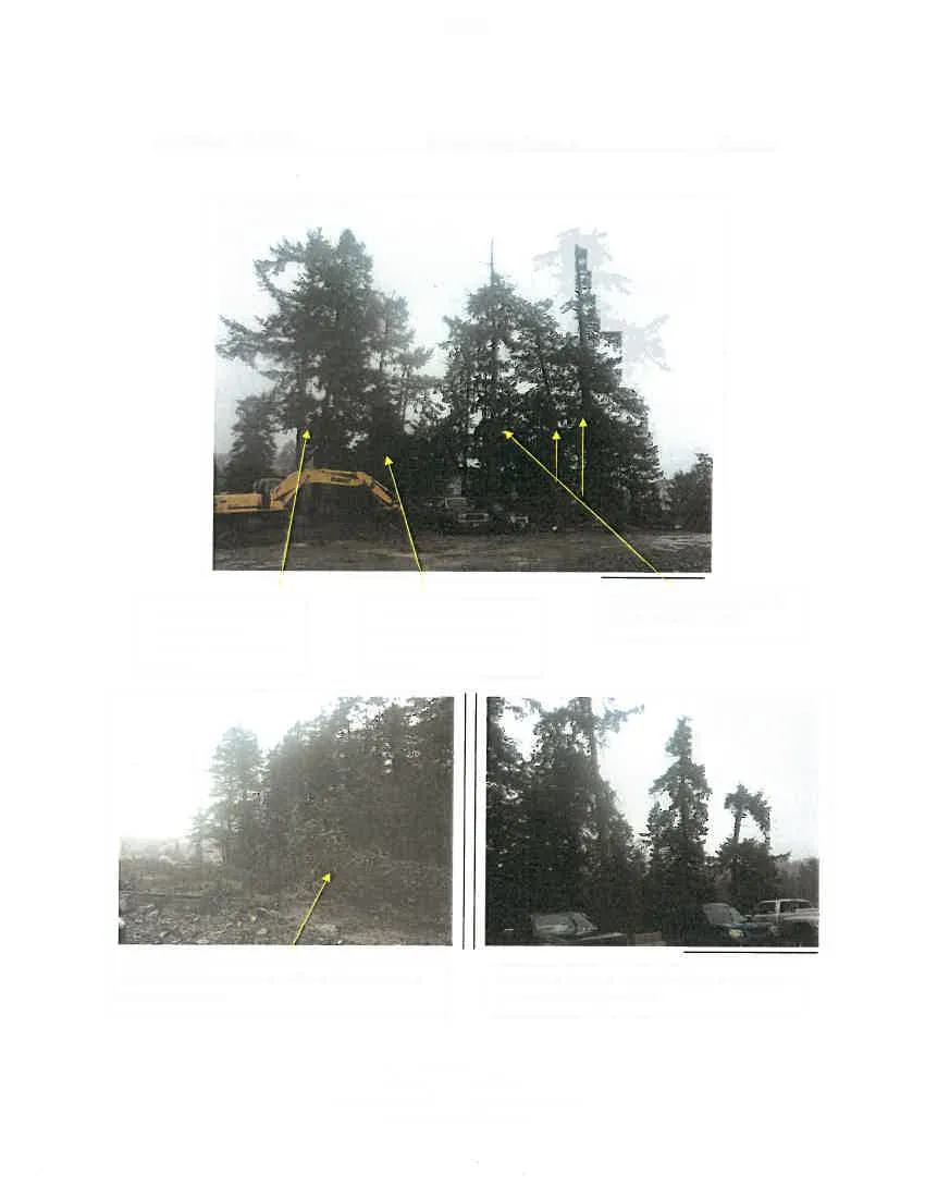
Observations: The majority of the trees that were on the site had been removed by the time of our most recent site visit. The Park area along the North and West boundaries has been isolated by the construction activity by chain link barrier fencing. Given the proposed construction plans and proposed grade changes there was no opportunity for retaining any of the existing trees within the center of the Phase 2 site and retaining trees along the periphery will be challenging. Of the trees that remain, there are a group of Douglas fir trees numbered: 24 – 30 along the East eastern property line, a group of Douglas fir trees in the North corner and a group of Garry oak trees along the Western boundary that were not tagged.
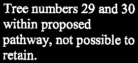
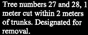
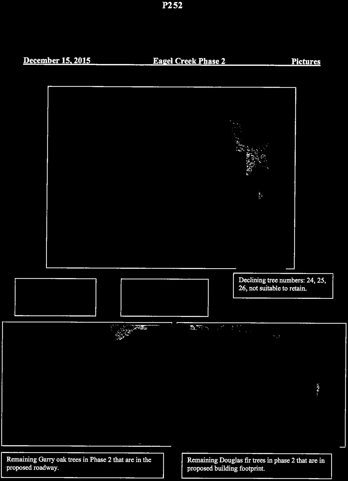
Douglas firs numbers 24 and 25 are showing health stress symptoms and are located within the proposed parking area and will not be possible to retain. Douglas fir number 26 is showing decline symptoms, will be impacted by the proposed parking area and is not suitable to retain. Douglas fir trees numbered 27 and 28 are located along the property line and there is a cut of approximately 1 meter in depth proposed within 2 meters from the tree trunks. At the time of our site visit there was fill soils placed over a portion of their critical root zones but no indications that there had been any excavation in that area. We anticipate that the excavation for the proposed pathway will necessitate their removal. Douglas fir trees number 29 and 30 are shown as being within the proposed gravel pathway and will not be able to be retained in the current design.
Recommendations:
- Barrier fencing: The areas, surrounding the trees to be retained, should be isolated from the construction activity by erecting protective barrier fencing. Where possible, the fencing should be erected at the perimeter of the critical root zones as defined in our Tree Resource Spreadsheet. The barrier fencing to be erected must be a minimum of 4 feet in height, of solid frame construction that is attached to wooden or metal posts. A solid board or rail must run between the posts at the top and the bottom of the fencing. This solid frame can then be covered with plywood, or flexible snow fencing (see attached diagram). The fencing must be erected prior to the start of any construction activity on site (i.e. site clearing, excavation, blasting, construction), and remain in place through completion of the project. Signs must be posted around the protection zone to declare it off limits to all construction related activity. The project arborist must be consulted before this fencing is removed or moved for any purpose. Solid hording material may also be required to protect the trunks of trees from mechanical injury if vehicles or machinery are permitted close to tree trunks and where blasting is required.
Blasting and rock removal: We anticipate that blasting will be required adjacent to the trees that are to be retained. When areas of bedrock are encountered near trees to be retained, the blasting to level these rock areas should be sensitive to the root zones located at the edge of the rock. Care must be taken to assure that the area of blasting does not extend into the critical root zones beyond the building and road footprints. The use of small low-concussion charges, and multiple small charges designed to pre-shear the rock face, will reduce fracturing, ground vibration, and reduce the impact on the surrounding environment. Only explosives of low phytotoxicity, and techniques that minimize tree damage, are to be used. Provisions must be made to store blast rock, and other construction materials and debris, away from critical tree root zones.
Douglas fir along East property line (numbers 27 - 30): If any of the Douglas fir trees along this property line are going to be retained, any excavation within their critical root zones must be supervised by the project arborist. At that time it can be determined whether they can be retained or not. If structural roots must be severed or the project arborist feels that the impacts have destabilized the trees or impacted the trees to a point where they will not survive, it will be recommended that they be removed.
Arborist Report Pictures
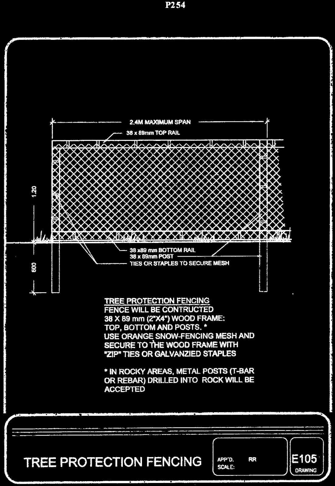
Tree Protection Fencing Detail
Entry Signage Renderings
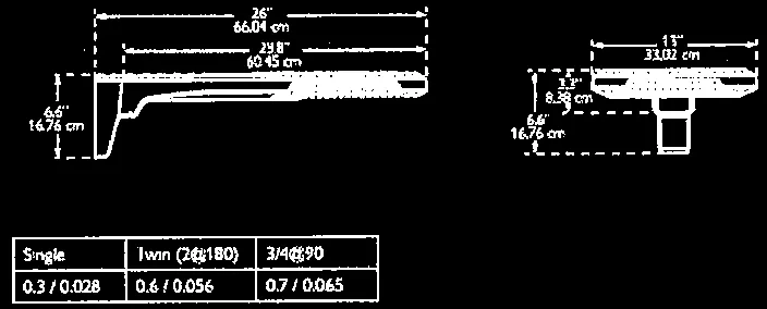
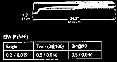
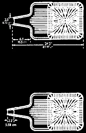
Luminaire Example
Document Images
(69)




Full Site Plan of South Building Phase A, showing building footprint (1209 SQ M), parking stalls, and future Phase B location



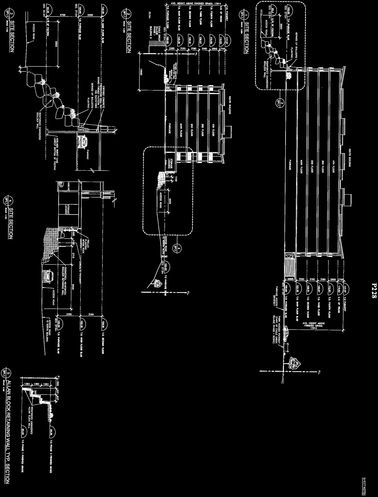


5 ALLAN BLOCK RETAINING WALL TYP. SECTION drawing with dimensions

Main Floor / Parking Floor Plan. Total area 13,018 SQ. FT. [1209 M2

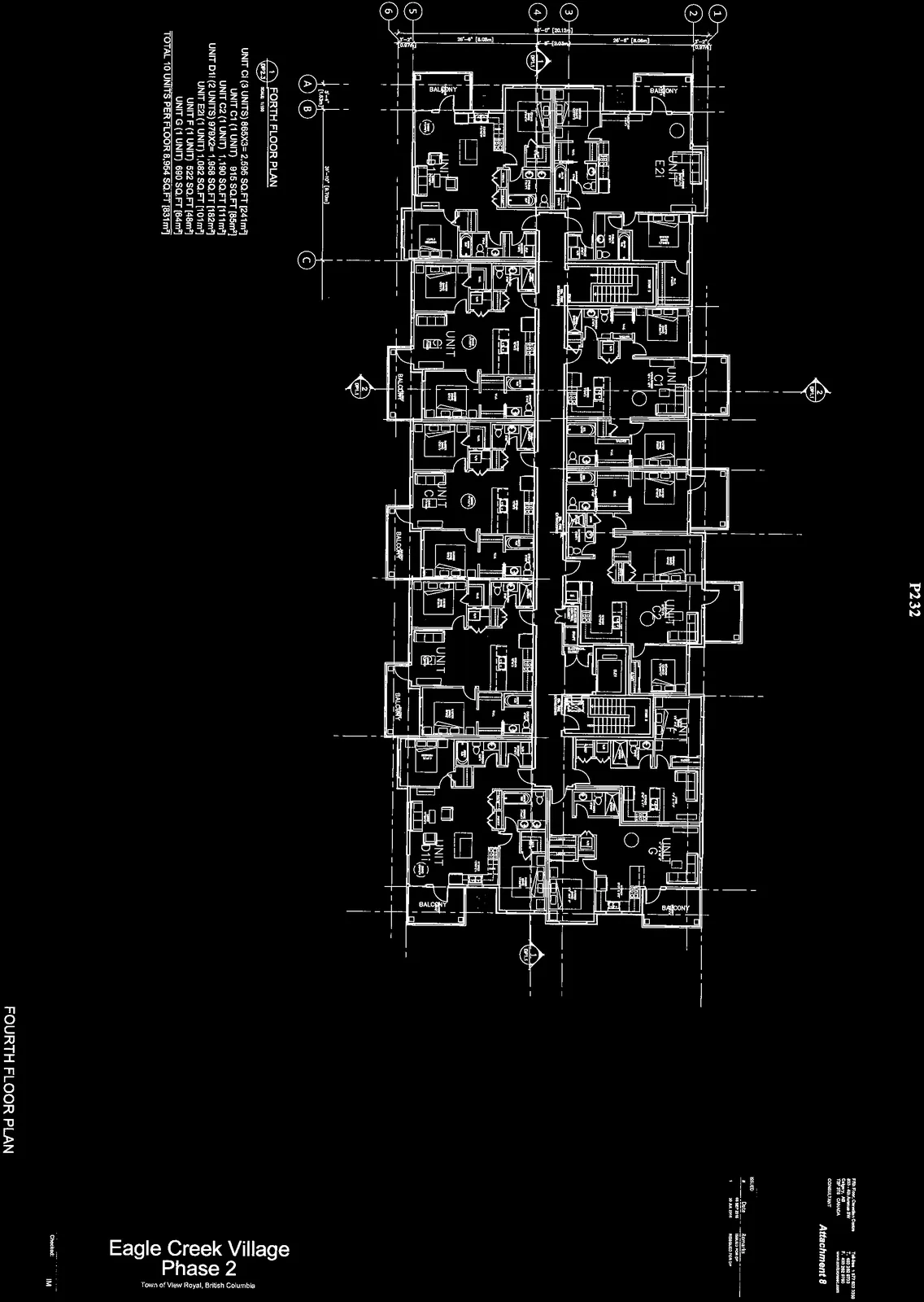

Detailed architectural floor plan for the main level of the South Building
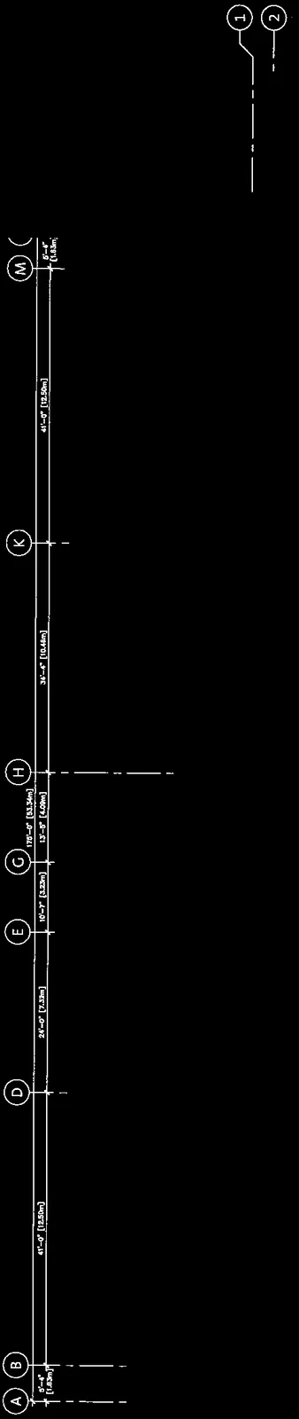



Roof plan layout showing sloped roof areas, mechanical units, and screening

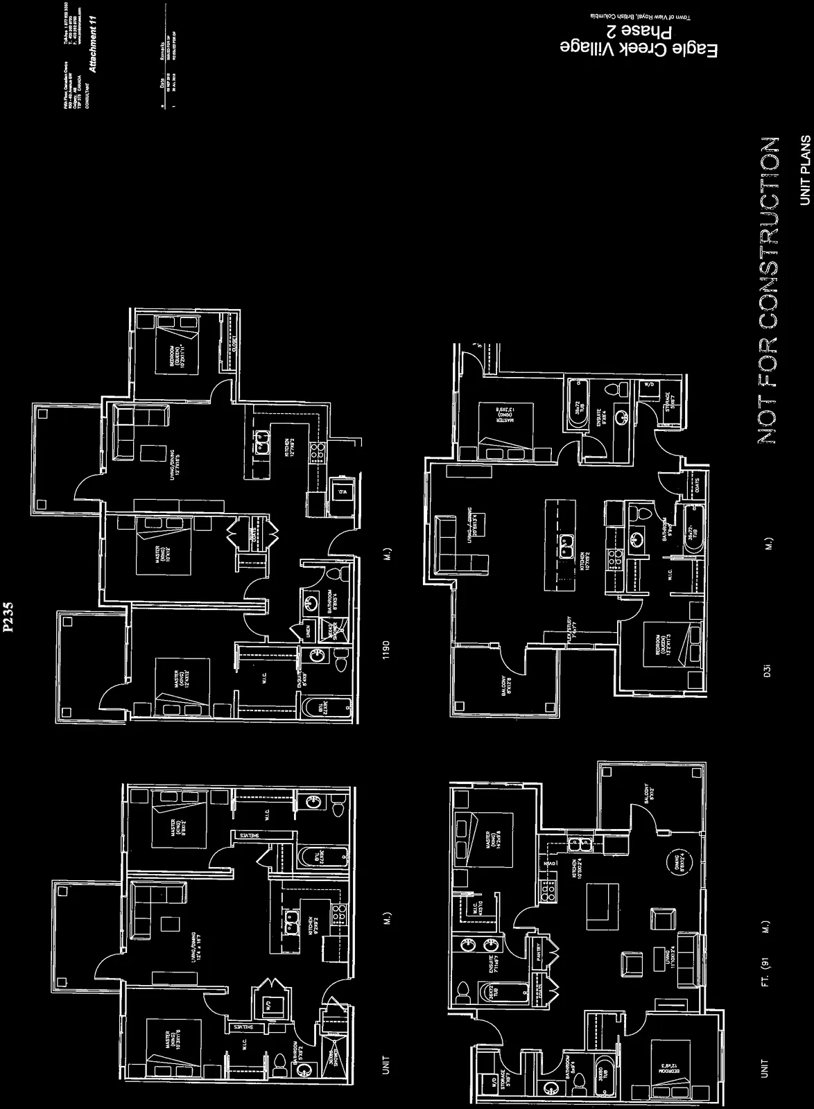
UNIT A - 635 SQ. FT. (59 SQ. M.) 2-bedroom unit layout


UNIT D1I - 979 SQ. FT. (91 SQ. M.) 2-bedroom unit layout



UNIT F - 522 SQ. FT. (49 SQ. M.) 1-bedroom unit layout


3 TYP. ROOFTOP SCREENING ELEVATION drawing




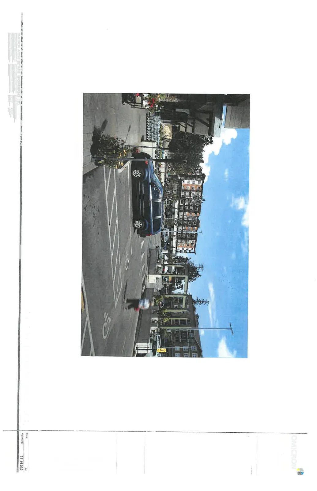
Rendering - VIEW FROM PHASE I PARKING LOT


Rendering - VIEW FROM PHASE II PARKING LOT illustrating the modern exterior design and surrounding landscape



2 BOLLARD DETAIL diagram


5 DRAINAGE DETAIL diagram

TYPICAL TRENCH SECTION diagram

LOCATION PLAN relative to Victoria General Hospital
Text for "Tree numbers 27 and 28, 1 meter cut within 2 meters of trunks. Designated for removal."



Detailed turning radius diagram for fire truck access