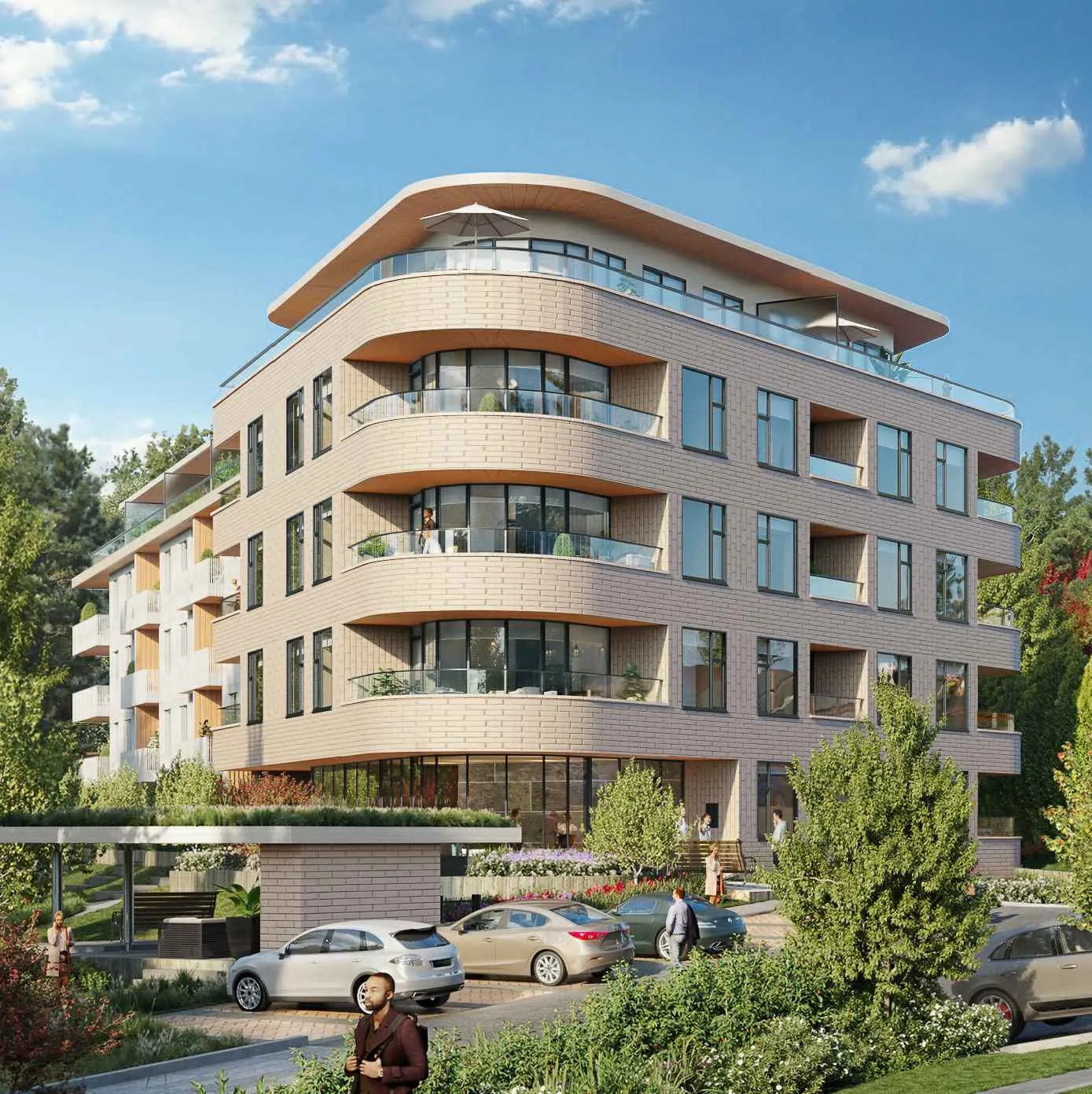
Issued April 4, 202282 total unitsBuilding height: 17.8m93 total parking spacesLEED Gold building standard target
PORTAGE PARK RESIDENCES | ISSUED FOR DP
PROJECT INFORMATION
PROJECT NAME: PORTAGE PARK RESIDENCES
CIVIC ADDRESSES: 167, 169, 171 ISLAND HIGHWAY, VIEW ROYAL, BC
PROJECT DESCRIPTION: 82 UNIT, 5 STOREY MULTI FAMILY RESIDENTIAL BUILDING
SITE AREA: 3780 SM
ZONING: CD-27
*AREA TAKEN TO CENTRE LINE OF CORRIDOR AND PARTY WALLS AND TO SHEATHING OF EXTERIOR WALLS
SITE COVERAGE
PROPOSED
PERMITTED
SITE COVERAGE
45% (1285 SM)
60%
OPEN SPACE RATIO
66% (2495 SM)
IMPERVIOUS SURFACE RATIO
45% (1717 SM)
80%
FLOOR SPACE RATIO (FSR) (EXCL. PARKING)
1.6 (6026 SM)
1.6
HEIGHT OF BUILDING (M)
17.8
18
SETBACKS + PROJECTIONS
SETBACKS
PROPOSED (M)
PERMITTED (M)
FRONT LOT LINE
18.9
18
WEST SIDE LOT LINES
4
4
EAST SIDE LOT LINE (PARK)
8.4
8
REAR LOT LINE
8.6
7
PARKING SUMMARY
TOTAL PARKING REQUIRED:
65
65 ONE BED UNIT X 1 SPACE/UNIT
26
13 TWO BED UNITS X 2 SPACES/UNIT
2
4 THREE BED UNITS X 2 SPACES/UNIT
93
TOTAL PARKING SPACES REQUIRED (EXCL. VISITOR)
PARKING PROVIDED:
PROPOSED
REQUIRED
RESIDENTIAL (SMALL & REGULAR)
92
92
ACCESSIBLE
4
4
TOTAL
94 SPACES
93 SPACES
VISITOR
9
n/a
TOTAL (INCLUDING DROP-OFF)
104 SPACES
BICYCLE STORAGE SUMMARY
TYPE
PROPOSED
REQUIRED (ASSUMED 1 PER UNIT)
TOTAL CLASS I BICYCLE SPACES
82 SPACES
82 SPACES
CLASS II BICYCLE SPACES
6
6
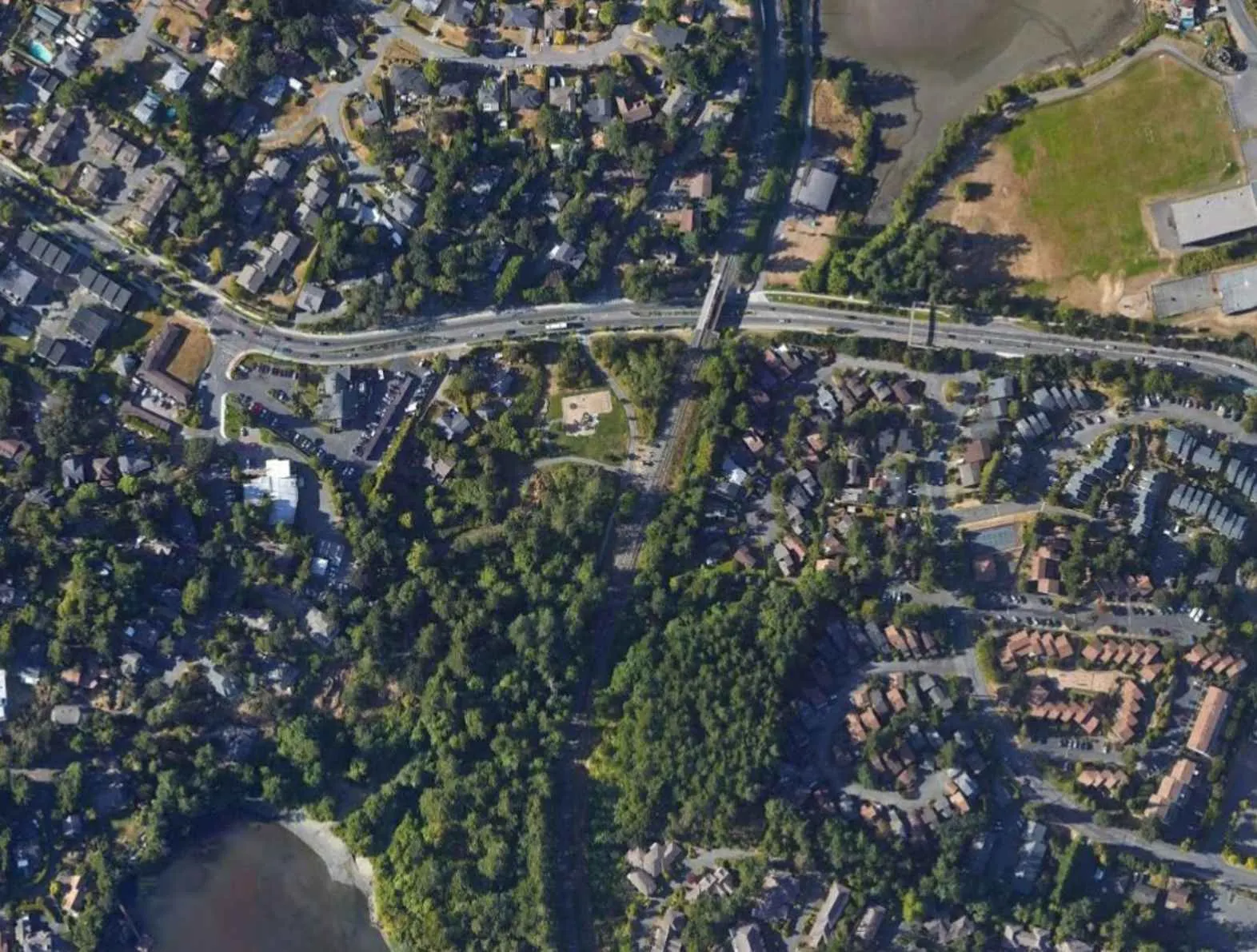
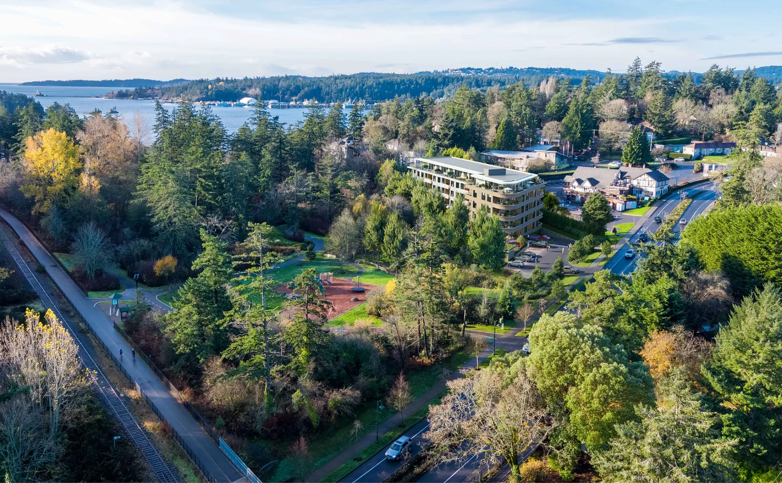
Top-down aerial photograph of the project site and surrounding neighborhood with Portage Inlet and the E&N Railway Trail visible.Aerial context diagram with red site boundary mask, labeling the site, Portage Park, Island Highway, Town Hall, Thetis Cove, and Portage Inlet.
PROJECT TEAM
OWNER & CONSTRUCTION MANAGER: GT MANN CONTRACTING LTD.
ARCHITECTURAL: URBAN WEST ARCHITECTURE INC.
STRUCTURAL: SKYLINE ENGINEERING
MECHANICAL: AVALON MECHANICAL
ELECTRICAL: TRIUMPH ELECTRICAL
CIVIL: MCELHANNEY
LANDSCAPE: FORSITE LANDSCAPE ARCHITECTURE
ARBORIST: TALBOT MCKENZIE AND ASSOCIATES
SURVEYOR: WEY MAYENBURG LAND SURVEYING INC
TRAFFIC: WATT CONSULTING GROUP
BUILDING CODE INFORMATION
APPLICABLE BUILDING CODE: PART 3 2018 BCBC
TYPE OF CONSTRUCTION: NEW BUILDING
NEW BUILDING AREA: 1,285 SM
NO. OF STORIES: 5
MAJOR OCCUPANCY CLASSIFICATION: GROUP C
BUILDING CLASSIFICATION: 3.2.2.50
CONSTRUCTION TYPE: COMBUSTIBLE
SPRINKLERED: YES
FIRE ALARM SYSTEM: YES
OCCUPANT LOAD: 208
DRAWING LIST
ARCHITECTURAL
A000 COVER & PROJECT INFO
A008 SPATIAL SEPARATION
A009 SURVEY PLAN
A010 CONTEXT PLAN
A011 SITE PLAN & GRADE CALCS
A015 SITE SECTIONS
A200 BUILDING ELEVATIONS
A300 BUILDING SECTIONS
A600 AMENITY PAVILION & BUILDING SIGNAGE
Page 65–86
A008 SPATIAL SEPARATION
Diagram of the Southeast Elevation (Pub Side) showing the building levels from EL. 10.25m (Parkade Entry) to EL. 31.3m (T/O Roof).Diagram of the Southwest Elevation (Island Highway) detailing floor levels and building heights.Diagram of the Northwest Elevation (Park Side) indicating grade levels and top of roof elevations.Diagram of the Northeast Elevation (Park Side) showing building height relative to the park grade.
Page 65–86
A009 SURVEY PLAN
Detailed survey plan of Lot 2, Lot A, and Lot B at 167, 169 & 171 Island Highway, showing property boundaries, existing structures, and topographical data.
Page 65–86
A010 CONTEXT PLAN
Context plan illustrating the proposed building location relative to surrounding landmarks such as Four Mile House Pub, View Royal Town Hall, and Portage Park.
Page 65–86
A015 SITE SECTIONS
Key plan indicating the location of the site sections.Site section 3 from the path to View Royal Ave through the proposed building.Site section showing the proposed building relative to the Island Highway street elevation, Portage Park, and Four Mile House.
Page 65–86
A020 AERIAL RENDERING
Photorealistic aerial rendering showing the proposed building within the neighborhood context, adjacent to Portage Park and the Four Mile House brewery.
Page 65–86
A021 STREET VIEW - SOUTHWEST FACING
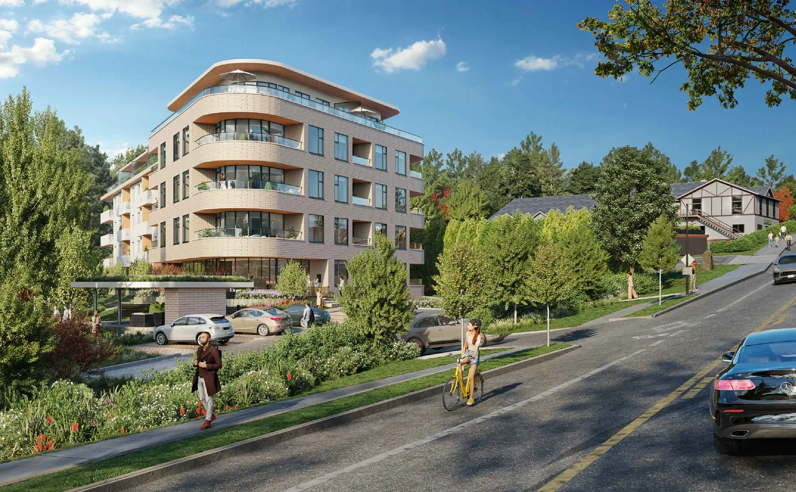
Street-level rendering of the proposed building from the southwest, featuring modern facade materials, balconies, and landscaping.
Page 65–86
A022 STREET VIEW - EAST FACING
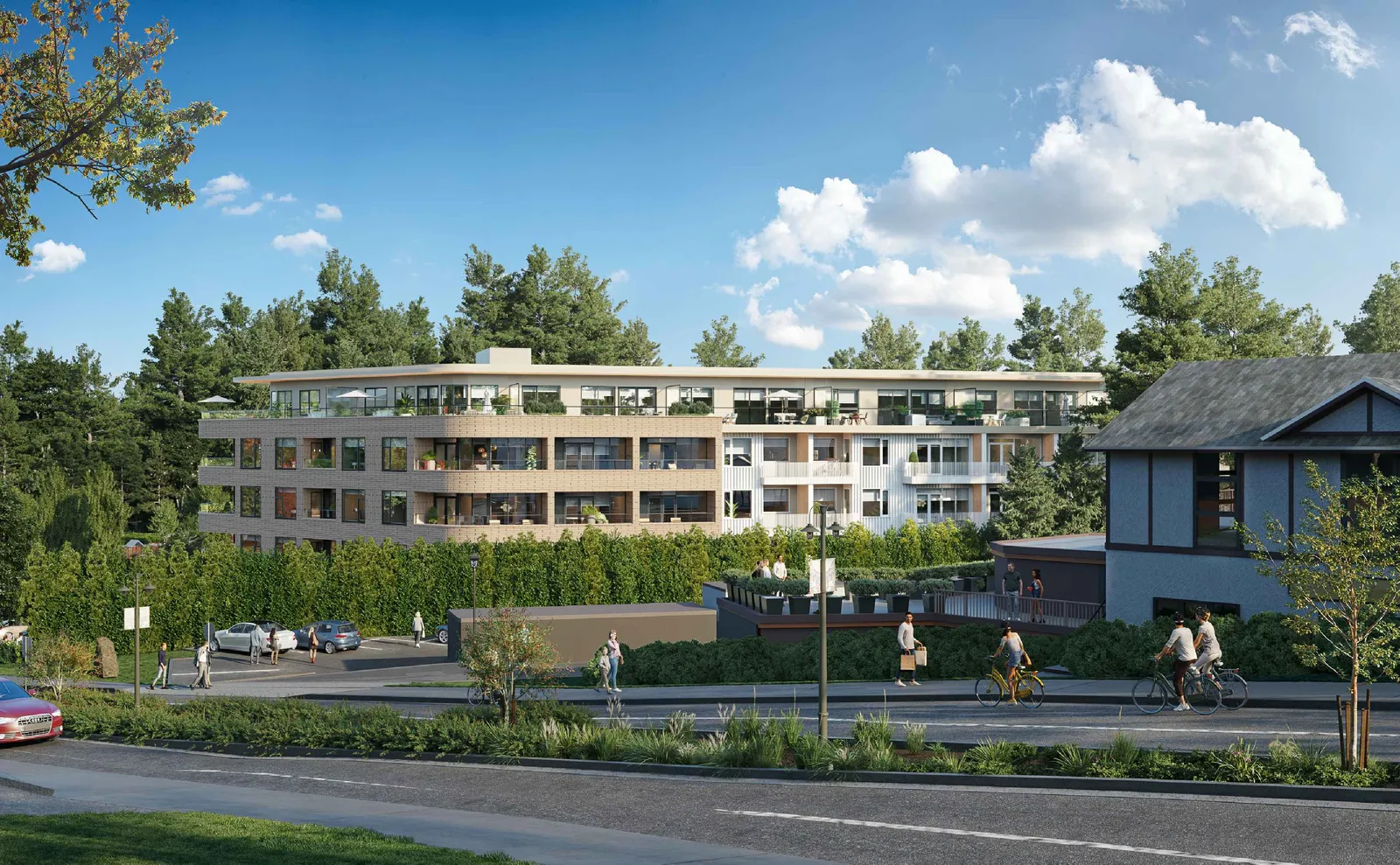
Street-level rendering from the east, showing the building's streetscape, pedestrian paths, and integration with the surrounding vegetation.
Page 65–86
A023 VIEW FROM PARK
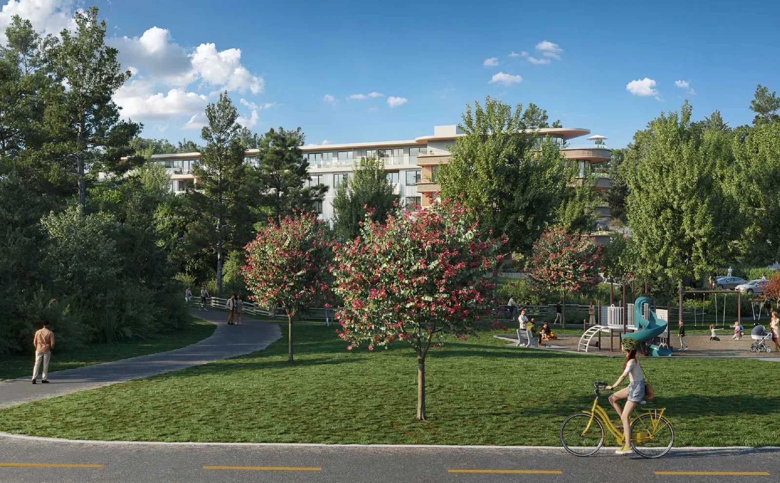
Rendering showing the view of the proposed building from Portage Park, highlighting the connection between the residential structure and the public green space.
Page 65–86
A024 MATERIAL PALETTE
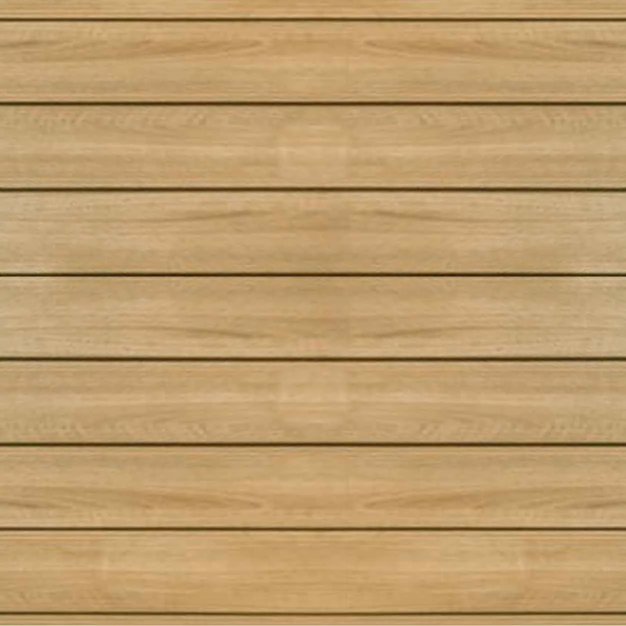
Visual collage of the building's exterior material palette, including various cladding types, window frames, and landscape elements.
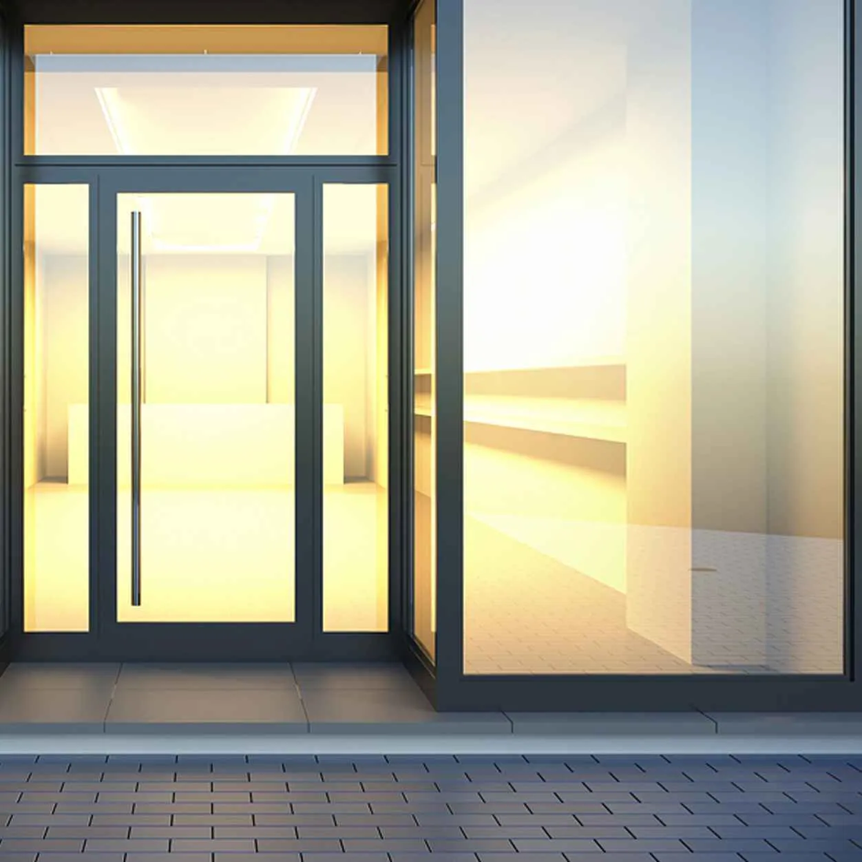
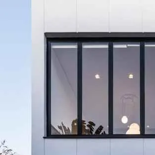
WINDOW FRAMES:Charcoal residential window frames / Charcoal lobby storefront windows
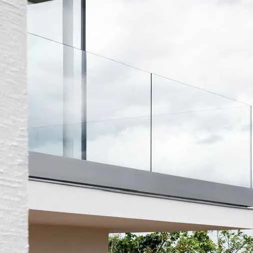
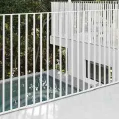
GUARDRAILS: /
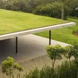
PAVILION:
Page 65–86
A100 LEVEL P1 PLAN
Detailed floor plan for Parking Level P1 showing parking stall layout, bike storage, and mechanical rooms.Detail drawing of typical regular and small car parking stall dimensions.
GARBAGE ROOM TABLE
BIN TYPE
NUMBER OF BINS
BIN DIMENSIONS (LxDxH)
WASTE SERVICE
6 YARD
1
1.83m x 1.68m x 1.52m
GARBAGE
3 YARD
1
1.83m x 1.07m x 1.22m
CARDBOARD
360 L
4
0.64m x 0.88m x 1.13m
MIXED CONTAINERS
360 L
3
0.64m x 0.88m x 1.13m
MIXED PAPER
240 L
4
0.62m x 0.70m x 1.09m
FOOD
240 L
1
0.62m x 0.70m x 1.09m
GLASS
Page 65–86
A101 LEVEL 1-4 PLANS
Level 1 floor plan showing residential units 100-117 and the main lobby entrance.Typical Level 2-4 floor plan showing residential unit layout (units 201-218).
Page 65–86
A102 LEVEL 5 & ROOF PLANS
Level 5 floor plan showing units 501-511 and the building roof plan with drainage layout.
Page 65–86
A300 SECTIONS
Cross-section diagram showing the vertical building structure from the parkade level P1 up to Level 5.Long-section diagram through the building and parkade ramp.
Page 65–86
A600 AMENITY PAVILION & BUILDING SIGNAGE
Architectural plans and elevations for a circular outdoor amenity pavilion featuring a fireplace and green roof.Detail of building signage "PORTAGE PARK RESIDENCES" on an architectural concrete wall.