Attachment 26 - Preliminary Framing Review (buepoint)
Engineer's preliminary framing review listing numerous structural deficiencies.
Attachment 26
Project Address: 12 Vickery Rd., Victoria, BC
Project No.: 10441
Date/Time: 2022.10.31 10:00AM, 2022.11.16, 2022.11.21
Type of Review: [X] Prelim Framing
Observations
- exterior sheathing has been covered
- post are not continuous through clerestory wall
- no rimboard beneath clerestory wall
- LVL beam plies have joints at mid-span
- no blocking above beams at roof valleys
- roof joists going in opposite directions from plan
- minimal backspan at roof overhang locations
- shearwall panel edges not properly blocked and nailed
- exterior wall sheathing not continuous to top plate
- lintel plies generally not laminated together
- lower GL-2 LVL beam does not extend to exterior corner per keynote 26
- beams generally continuous (ply joints do not land on posts)
- bumpout wall at front of building has been pulled back to bear above concrete OK
- entry roof has not been framed per plan
- posts missing under some LVL beams
- 2x6 post installed instead of PSL at end of GL-2 shearwall
- 8x8 posts generally replaced with 5-ply 2x8 built-up D.fir posts
- holddowns missing at shearwalls
- straps missing at shearwalls
- straps generally missing at drag strut locations
- screws used in hangers
- LSL drag strut not installed along shearwall per keynote 22
- roof joist aligns parallel above master bedroom wall, no blocking across wall for overhang
- GL-3 LVL above master bedroom done as 2-ply, plan shows 3-ply
- shearwall end-studs fastened to adjacent posts generally with (2) screws @ 12" o/c
- cantilever roof joists not aligned with chimney walls
- GL-D beam done as 11-7/8" LVL, does not extend over shearwall
- LVL beam notched at GL-3A corner
- some built-up posts have discontinuous plies
- LVL beams generally connected with hangers where keynote 6 noted
- cracked joist at cant. front deck backspan
- deck joists generally fastened to rimboard through sheathing, no ledgers
- dropped deck beams generally 5-ply 2x8 D.fir, some plies discont.
- straps in main floor system either not installed, or installed vertically when horizontal is called for
- straps missing nails
- some floor panel edges unblocked
Framing
| Framing Item | Reviewed | Incomplete | N/A | Comments |
|---|---|---|---|---|
| Conformance with truss spec: | [X] | - penetrations to be reviewed at a later date | ||
| Conformance with I-joist drawings: | [X] | |||
| Beam and girder bearing: | [X] | - client to confirm A35's have been installed between roof joist and GL-C shearwall top plate per keynote 27 | ||
| Continuity of top plates: | [X] | |||
| Lintels/openings: | [X] | |||
| Shearwalls/Fastening/Hold-downs: | [X] | |||
| Continuity of tall walls: | [X] | - LUS26 hanger or better sufficient for resisting uplift from outlook joist backspan | ||
| Floor system blocking for point loads: | [X] | |||
| Wall sheathing: | [X] | |||
| Wind girts: | [X] | |||
| Post to beam free standing: | [X] | |||
| Fasteners in hardware: | [X] | |||
| Shearwalls to floor system: | [X] | |||
| Penetrations: | [X] | |||
| LLRS consistent: | [X] |
[X] Further Review Required
Reviewed by: Trevor Kinnee, EIT
Instructions
- provide photos of exterior shearwall sheathing nailing w/ measuring tape in frame
- install holddowns and straps (as applicable) at shearwall ends where missing
- provide blocking and nailing at all shearwall panel joints
- extend exterior wall sheathing to lap over top plate, block and nail sheathing panel joints (6" o/c for regular walls and 3" o/c for shearwalls)
- provide horizontal straps connecting framing members per plan (see keynotes 14, 15, 20, and 24)
provide photos of shearwall bottom plate fastening for reviewbottom plates nailed to each joist, reviewed 2022.11.29- provide nails between shearwall end studs and posts per keynote 10
provide (2) 3/8" x 7 1/4" GRK RSS @ 12" o/c through 5 ply built-up D.Fir posts (alternating faces)shearwall sheathing laps with rim boardfor rafters supporting outlook joists, provide full depth blocking @ 48" o/c against adjacent rafters where outlook joist backspans are hung from SPF rafters, double up rafter.blocking installed, SPF rafters OK- where LVL beams have ply joints at midspan, sister an additional continuous LVL ply to match the number of continuous plies noted in the beam schedule
- provide min. (2) 3/8" GRK's between LVL beams and 5-ply built-up posts
cut continuous LVL beams at supports, ensure adequate bearing is maintained— for continuous beams where plans note separate spans, add a continuous ply and provide (5) GRK's @ 12" o/c within 4ft of midspan supports, provide (3) GRK's 12" o/c elsewhereprovide blocking between rafters above exterior walls- install LSL drag strut alongside master bedroom shearwall per keynote 22 on plans
replace post plies that have joints at mid height, all post plies must be continuous- provide blocking between GL-2 shearwall studs past GL-A and install MSTC28 strap between added blocking and lower LVL beam end at GL-A
- provide entry roof structure as marked up in detail (see below)
- add ply to GL-2 lower roof beam between GL-C and -D (see markups below)
- provide MSTA24 strap between beam and post at GL-2C
- frame clerestory wall as SW1 shearwall between GL-D and nearest opening (min. 5'-0" length)
- provide MSTC52 strap at GL-D end of clerestory shearwall between shearwall end post and post below
- provide MSTC48B3 pre-bent strap between clerestory shearwall end post and beam below at mid span
provide photos of the above works completed
Entry Roof Structure Markups
Diagram Notes:
- #12 (Note in red)
- #17 (Note in red)
- (5) GRK's @ 12" o/c (Note in red)
- (3) GRK's @ 12" o/c (Note in red)
- existing 2x12 ridge OK to cantilever over exterior wall (Note in red)
Document Images
(14)
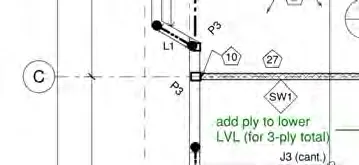
Diagram crop showing grid line C, SW1 shearwall, and "add ply to lower LVL (for 3-ply total)" instruction
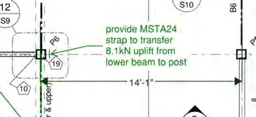
Diagram crop showing instruction to "provide MSTA24 strap to transfer 8.1kN uplift from lower beam to post"
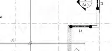
Diagram crop showing detail at grid line C and L1 beam
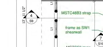
Diagram crop showing MSTC48B3 strap, "frame as SW1 shearwall", and MSTC52 strap instructions
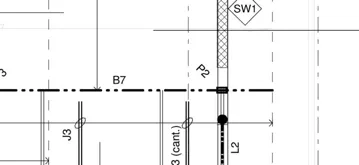
Diagram crop showing B7 beam and SW1 shearwall framing near grid line D
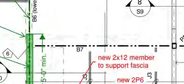
Diagram crop showing "5'-0" min." dimension for SW1 shearwall and "new 2x12 member to support fascia" instruction
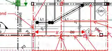
Diagram crop showing 8'-0" dimension between B6 and B9 beams
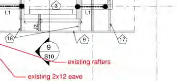
Diagram crop showing existing rafters and existing 2x12 eave
Diagram crop showing instruction for "new 6x6 post to bear on existing foundation"
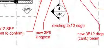
Diagram crop showing "new 2P6 kingpost" and "existing 2x12 ridge"
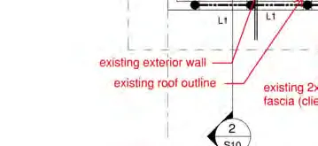
Diagram crop showing existing exterior wall, roof outline, and "existing 2x12 SPF fascia (client to confirm)"
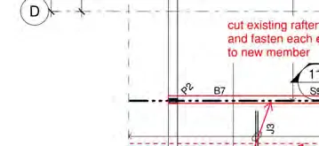
Diagram crop showing instructions at grid line D to "cut existing rafters and fasten each end to new member"
Diagram crop showing red rectangular framing detail