Appendix
Attachment 28 - Detailed Framing Review and Markup (buepoint)
March 4, 2025Pages 85–891 section
Detailed structural review report with plans marked up to show deficiencies and required corrections.
March 14, 2023Mark Buesink, structural engineerSignificant structural issues noted on plans
Field Review Report
Project Address: 12 Vickery Road., Victoria, BC Project No.: 10441 Contact: John Becker Date/Time: 2023.03.14 2:30PM
Type of Review:
- Footings
- Foundation Walls
- Sheathing
- Framing
- Final:
- Other:
Observations:
- ceiling framing at entry will offer some lateral support to front wall
- floor is not level, has high spots and low spots - structurally not a concern
- feels like floor has some soft spots - looks like floor sheathing is discontinuous between joists
- post at gridline C3 is 6x6 in lieu of 8x8 per plans - OK
- B3 beam near entry only one-ply continuous, 11-7/8" deep, spans about 8ft rather than 3ply 9-1/4" per plans - OK
- none of the dropped beams supporting the front deck are continuous, multiple ply joints
- P2 post missing beneath B7 near gridline D
- some walls still do not have sheathing continuous to top plate
- front deck beams appear to be directly in contact with concrete
- lintels have bottom plate but no top plate per drawings
- dropped purlins supporting roof above backroom not given proper bearing or hangers in exterior wall
- no rimboard along lower roof rafters along GL-2 per detail 2/S9
- no blocking between front deck joists above bearing locations
- no perpendicular blocking between GL-A beam and adjacent joist per detail 1/S9
- no lintel provided above opening for fireplace near GL-D
- front deck cantilevering joists have very little backspan
- 12'-9" front deck dropped beam has no continuous plies
- single 2x6 supporting entry roof edge
- horizontal holddown installed at GL-2A, could not verify fastening of scabbed material
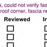
- roof sheathing not continuous at back roof corner, fascia not continuous along edge
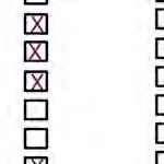
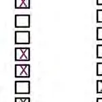
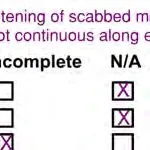
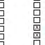
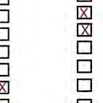
| Framing: | Reviewed | Incomplete | N/A | Comments: |
|---|---|---|---|---|
| Conformance with truss spec: | [ ] | [ ] | [X] | - concrete topping for leveling the floor should NOT be used as the floor framing was not designed for the additional weight |
| Conformance with I-joist drawings: | [ ] | [ ] | [X] | |
| Beam and girder bearing: | [ ] | [X] | [ ] | |
| Continuity of top plates: | [X] | [ ] | [ ] | - finishes may deform resulting from settlement of as-built framing as there are several places where the framing doesn't fit well or is shimmed or blocked or on multiple plies of horizontal framing |
| Lintels/openings: | [X] | [ ] | [ ] | |
| Shearwalls/Fastening/Hold-downs: | [X] | [ ] | [ ] | |
| Continuity of tall walls: | [ ] | [ ] | [X] | |
| Floor system blocking for point loads: | [ ] | [ ] | [X] | |
| Wall sheathing: | [X] | [ ] | [ ] | |
| Wind girts: | [ ] | [ ] | [X] | |
| Post to beam free standing: | [ ] | [ ] | [X] | |
| Fasteners in hardware: | [X] | [ ] | [ ] | |
| Shearwalls to floor system: | [X] | [ ] | [ ] | |
| Penetrations: | [X] | [X] | [ ] | |
| LLRS consistent: | [ ] | [ ] | [ ] |
Instructions
see following pages for instructions and sketches
- Further Review Required
- Generally conforms if the above instructions are completed
- Reviewed for general conformance to our structural design intent
Reviewed by: Mark Buesink, P.Eng.
Instructions:
- provide confirmation of holddowns and straps (as applicable) at shearwall ends where missing
- extend wall sheathing to lap over top plate, block and nail sheathing panel joints (6" o/c for regular walls and 3" o/c for shearwalls)
- removed
- provide nails between shearwall end studs and posts at keynote 10 location on gridline 4 (see markup next page)
- for continuous dropped roof beams along gridlines 2 and 3, provide (5) GRK's @ 12" o/c within 4ft of midspan supports, provide (3) GRK's 12" o/c elsewhere
- nail sheathing for master bedroom shearwall to top plate and LVL rimjoist above per shearwall schedule
- sheath inside face of clerestory wall between GL-D and nearest opening as SW1 shearwall (min. 5'-0" length), see markup on following page
- provide MSTC48B3 pre-bent strap between clerestory shearwall end post and beam below at mid span
- along sections of continuous beams that remain as two-ply provide (5) GRK's @ 8" o/c within 4ft of midspan supports (see sketch below)
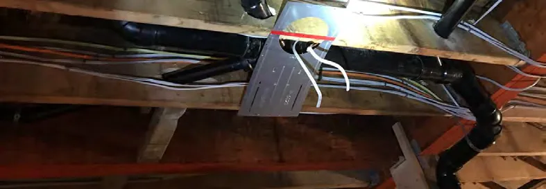
- pack out joist at large toilet penetration near GL-C (see photo following) and add two 2x6 SPF joists, one either side of where toilet line is going spanning minimum 3' past penetration on each side.
- where floor joist laps with LVL beam under shearwall between GL-B and -C, provide (5) 3" nails @ 6" o/c between joist and LVL, see markup below (since keynote 15 was not done)
- sister 2x12 SPF ply to backspan of cracked front deck cantilever joist (near GL-2)
- sister an additional 2x6 ply to the 2x6 supporting the entry roof edge (for two plies total, see sketch following)
- client to confirm nailing used at GL-2A to scab 2x4's to bottom edge of LVL beam to connect horizontal holddown
- provide 2-ply 2x6 post near GL-4 and D to support B7 beam as noted on plans
- nail sheathing to beam above GL-2 shearwall near GL-A per shearwall schedule
- removed
- confirm that A35's installed between GL-C shearwall top plate and roof joist per keynote 27 (comment on original framing review slip requested this to be confirmed)
- provide min. 2x6 lintel above fireplace opening
- provide continuous structural fascia between roof corner and ridge along back roof overhang since roof sheathing is not continuous
- client to confirm A35's have been installed between roof rafter blocking and shearwall top plates per detail 6/S9
- provide blocking between lower roof rafters along GL-2 in lieu of rimboard per detail 2/S9
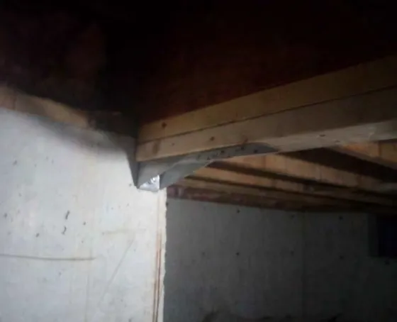
- add studs either side of exterior wall posts supporting dropped purlins in back room, provide beam hangers to support purlins
- provide new joists to support cantilevered front deck c/w full backspan to gridline D wall, sister to existing joists (see markup below)
- replace long-span front deck beam with 4-ply SPF no. 1/2 or 8x8 D.fir per plan
- provide perpendicular joist blocking between GL-A beam and adjacent joist per detail 1/S9
provide photos of the above works completed
Page 85–89
Document Images
(75)



















Extracted from: 2025 03 04 Council Agenda - Agenda - Pdf