Study for Site Serviceability - 102 Atkins
Engineering review of utility requirements for nine single-family homes, covering water, sanitary sewer, storm water management, and site access.
October 8, 2014
Town of View Royal 45 View Royal Avenue Victoria, BC V9B 1A6
Attn: Lindsay Chase
Re: 102 Atkins – Study for Site Serviceability
Dear Ms. Chase:
Westbrook Consulting Ltd. has been engaged to review the available site services for the proposed development of 102 Atkins.
PROJECT UNDERSTANDING
The property is located near the northwest corner of Atkins Road and Chilco Road and is bordered to the south by the Galloping Goose regional trail, to the north by the E&N Railway, and to the east by Chilco Road. The property is triangular in shape with the west end forming the point of the triangle with the E&N Railway and Galloping Goose trail rights of way converging at that location.
We understand the proposed development is to be nine single family homes.
The project is proposing to have a common strata road along the south property line, with the living units located to the north of the strata road.
The following outlines the preliminary design of the following services:
- Domestic Water
- Fire Service
- Sanitary Sewer
- Storm Water Management
- Gas
- Power and Communications
- Access
The infrastructure corridor within the development will be the proposed access road.
DOMESTIC WATER SERVICE
There is an existing 150 mm diameter Polyvinyl Chloride (PVC) watermain, installed in 2003, located within the Atkins Road allowance, and from which the existing water service to 102 Atkins originates.
It is proposed to replace the existing service with one that is adequately sized for the proposed development.
The proposed domestic water service is sized preliminarily as per the design criteria below:
- AWWA M22 form
- BC Plumbing Code
AWWA Calculations
The AWWA M22 form is used by many municipalities for sizing water services to individual homes and larger developments. It is based on the total number of fixtures within a house and gives an expected flow based on the fixture count. Attached is the AWWA M22 form completed with an assumed number of fixtures for each unit and the calculated total flow expected from the development. The form indicates a potential flow of approximately 78 USGPM, which, based on the AWWA supporting documents will require a 50mm domestic service.
BC Plumbing Code Calculations
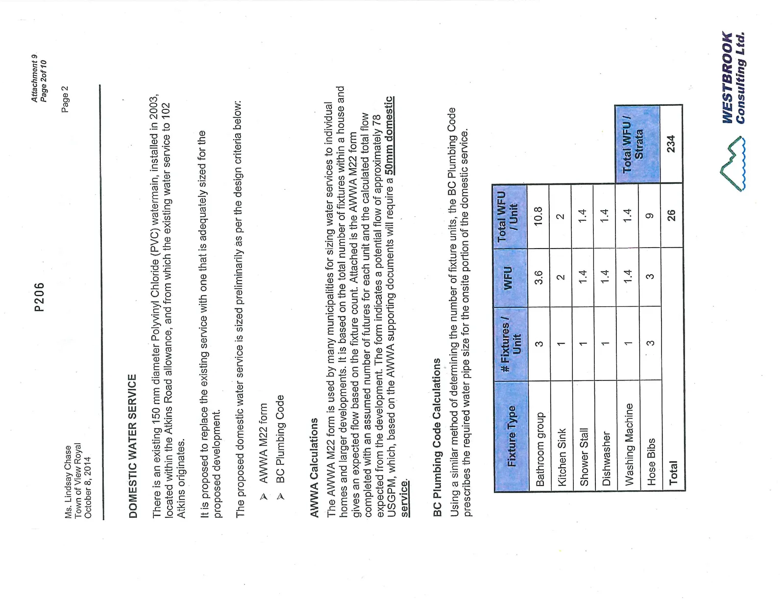
Using a similar method of determining the number of fixture units, the BC Plumbing Code prescribes the required water pipe size for the onsite portion of the domestic service.
| Fixture Type | # Fixtures / Unit | WFU | Total WFU / Unit | Total WFU / Strata |
|---|---|---|---|---|
| Bathroom group | 3 | 3.6 | 10.8 | |
| Kitchen Sink | 1 | 2 | 2 | |
| Shower Stall | 1 | 1.4 | 1.4 | |
| Dishwasher | 1 | 1.4 | 1.4 | |
| Washing Machine | 1 | 1.4 | 1.4 | |
| Hose Bibs | 3 | 3 | 9 | |
| Total | 26 | 234 |
Based on 234 water fixture units the BC Plumbing Code requires a 62mm diameter service for the internal domestic water service and an a flow of 4.69 L/s.
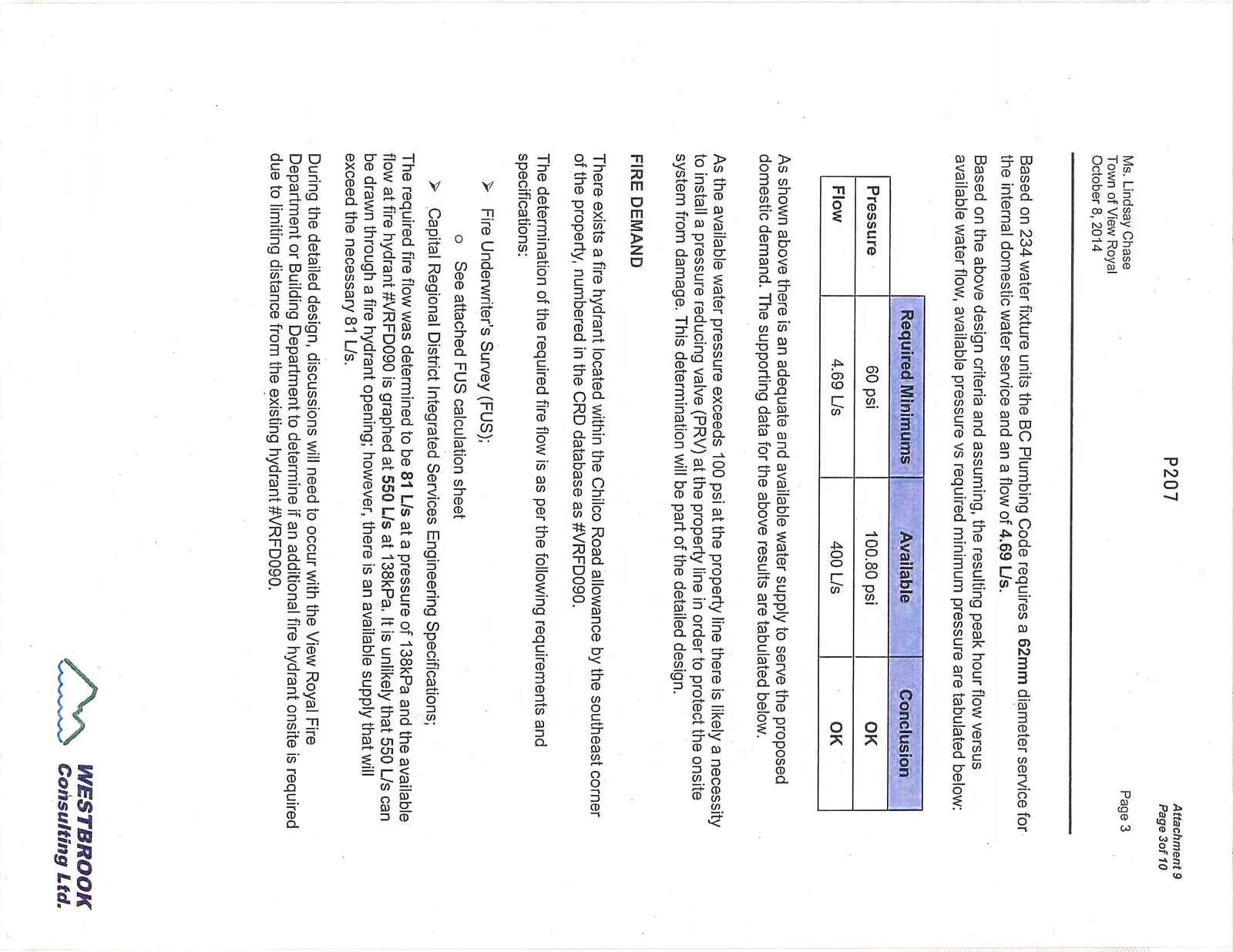
Based on the above design criteria and assuming, the resulting peak hour flow versus available water flow, available pressure vs required minimum pressure are tabulated below:
| Required Minimums | Available | Conclusion | |
|---|---|---|---|
| Pressure | 60 psi | 100.80 psi | OK |
| Flow | 4.69 L/s | 400 L/s | OK |
As shown above there is an adequate and available water supply to serve the proposed domestic demand. The supporting data for the above results are tabulated below.
As the available water pressure exceeds 100 psi at the property line there is likely a necessity to install a pressure reducing valve (PRV) at the property line in order to protect the onsite system from damage. This determination will be part of the detailed design.
FIRE DEMAND
There exists a fire hydrant located within the Chilco Road allowance by the southeast corner of the property, numbered in the CRD database as #VRFD090.
The determination of the required fire flow is as per the following requirements and specifications:
- Fire Underwriter's Survey (FUS);
- See attached FUS calculation sheet
- Capital Regional District Integrated Services Engineering Specifications;
The required fire flow was determined to be 81 L/s at a pressure of 138kPa and the available flow at fire hydrant #VRFD090 is graphed at 550 L/s at 138kPa. It is unlikely that 550 L/s can be drawn through a fire hydrant opening; however, there is an available supply that will exceed the necessary 81 L/s.
During the detailed design, discussions will need to occur with the View Royal Fire Department or Building Department to determine if an additional fire hydrant onsite is required due to limiting distance from the existing hydrant #VRFD090.
SANITARY LOAD
There exists a 200mm diameter municipal sewer main fronting the development on Chilco Road from which the existing 100mm sanitary service originates.
It is proposed to replace the 100mm sanitary service with a 150mm sanitary service to serve the development.
In order to size sanitary pipes within a strata two methods are followed and compared to see which governs, the methods are the BC Plumbing Code and good engineering practice.
The following design criteria were used in the determination of the sanitary flows for the proposed development.
For residential flows:
- BC Plumbing Code;
- Estimated fixture count of 30 sewer fixture units (SFU) per dwelling (270 SFU total for the proposed development).
- MMCD Design Guideline Manual, 2005;
- Residential Average Daily Dry Weather Flow = 300 litres per capita per day
- Population = 4 per unit (assumed)
- Peaking Factor Harmon Equation ($PF = 6.75P^{-0.11}$)
- P = Population
- Infiltration = 0.17 l/s/ha
- Catchment size = 0.56 ha
Using the BC Plumbing Code a 150 mm pipe at 0.75% slope has the capacity to convey 600 SFU which exceeds the estimated 270 SFU for the proposed development.
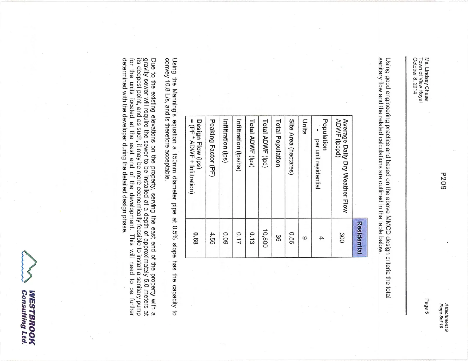
Using good engineering practice and based on the above MMCD design criteria the total sanitary flow and the related calculations are outlined in the table below.
| Residential | |
|---|---|
| Average Daily Dry Weather Flow ADWF (lpcpd) | 300 |
| Population - per unit residential | 4 |
| Units | 9 |
| Site Area (hectares) | 0.56 |
| Total Population | 36 |
| Total ADWF (lpd) | 10,800 |
| Total ADWF (lps) | 0.13 |
| Infiltration (lps/ha) | 0.17 |
| Infiltration (lps) | 0.09 |
| Peaking Factor (PF) | 4.55 |
| Design Flow (lps) = (PF * ADWF + Infiltration) | 0.68 |
Using the Manning's equation a 150mm diameter pipe at 0.5% slope has the capacity to convey 10.8 L/s, and is therefore acceptable.
Due to the existing elevations on the property, serving the east end of the property with a gravity sewer will require the sewer to be installed at a depth of approximately 5.0 meters at its deepest point, and as such, it may be more economically feasible to install a sanitary pump for the units located at the east end of the development. This will need to be further determined with the developer during the detailed design phase.
STORM WATER MANAGEMENT
Storm water management shall be designed to meet the Town of View Royal Schedule "B" Section 3, which requires:
- Zero increase in runoff;
- Design storm = 10 years at 10 minute duration;
- Minimum runoff coefficient = 0.60, actual runoff coefficient to be determined using effective area calculations;
The property is divided into two catchments:
- The western 2600 square meters drains to a well-defined drainage channel on the north side of the Galloping Goose trail. The channel is then directed via a culvert beneath the trail to a drainage swale/ditch system on the north side of Atkins which flows westward toward 149 Atkins Road where the municipal system drains south to Millstream Creek;
- The eastern 4500 square meters drains to a drainage swale along the north side of the Galloping Goose trail. The swale directs runoff toward Chilco Road where it looks to enter a lawn basin at the northwest corner of 94 Chilco Road. The lawn basin drains via a 150mm drain pipe to an outlet northwest of 80 Chilco Road and into a deep municipal drainage channel that flows toward Millstream Creek within Burchill Park.
The intent of the storm water management plan is to minimize altering flow routes of the current catchments and not produce a negative impact on the downstream environment.
To insure there is no net increase in runoff from the two catchments, the post development runoff rate will be compared to the redevelopment rate of runoff; the difference of which will either be detained on site or be infiltrated to the natural ground.
If there is a need to detain the runoff due to the runoff exceeding the infiltrative capacity of the natural soil, the detained volume stored will be released at the predevelopment rate of the two year design storm.
As the runoff from the site currently sheet flows to the south, to be picked up by the existing swale / channel along the Galloping Goose trail, it is proposed to maintain this flow route by the following:
- Roof water and runoff from the common road will be collected and directed to a detention system located beneath the common road.
- The detention cells will be interconnected to an infiltration trench that will be located along the southern boundary of the property.
- The infiltration trench will be designed such that runoff is absorbed by the natural ground, and should break out occur, it will flow down the existing bank north of the trail and along the current flow route.
- An overflow route will be provided to interconnect to the existing municipal drain located with a statutory right of way behind 94 Atkins Road.
GAS
It is proposed to serve the development with natural gas. The detailed design of which will be done by the gas utility, FortisBC, and is intended to originate from the existing intermediate pressure gas main within the Chilco Road right of way.
The presence of an intermediate gas main within the Chilco Road allowance will require that an excavation within 30 meters of the gas main will require written permission from FortisBC, even if the excavation is not related to gas.
POWER AND COMMUNICATIONS
Power will be designed by BC Hydro and is anticipated to originate from the existing dip service and junction box located by the power pole at the north west corner of Atkins Road and Chilco Road. The dip service is a primary dip service and will need to be transformed to a lower voltage, as such, a transformer will need to be installed within the property. Its exact location will be determined with the electrical consultant during the detailed design phase.
Communications in the form of Shaw Cable and Telus will be brought from either the existing dip service from the pole at the northwest corner of Chilco and Atkins Roads or from the existing dip service from the pole at the intersection of Chilco and the E&N railway. Either location works well for the proposed development as each is close to the proposed infrastructure corridor.
ACCESS
The access will be provided from Chilco Road and will be in the form of a private strata road.
As the access will be a private road it is considered a "driveway". The onsite portion of the road will be designed to meet the appropriate Town of View Royal engineering specifications and good engineering practice, as listed below:
- Connection to a public highway, namely Chilco Road;
- Minimum level distance = 7.5 meters from centre of Chilco Road.
- Centreline radius of at least 12.0m;
- Overhead clearance of at least 5m;
- A maximum centre line gradient of fifteen percent (15%);
- Change of gradient of not more than one in 12.5 over a minimum distance of 15m;
- Pavement and structural design in accordance with the requirements of the Town's engineering specifications, Schedule B, Section 10, for local streets.
- A minimum clear paved surface width of 4.5 graded at a two percent (2%) cross fall either to curbing or to gravel shoulders.
- Turn-around to be provided to meet specification drawing R9 for any dead end portion of an access route exceeding 90m;
CONCLUSION
We feel that the above mentioned servicing will meet the requirements of the Town of View Royal bylaws as well as the needs of the development. The details of which will be required to be defined with the Town's engineering department during the development stage.
If you have any questions or comments, please contact the undersigned.
Yours truly,
WESTBROOK CONSULTING LTD.
Bruce Crawshaw, P.Eng., LEED AP Project Engineer
Document Images
(8)