This site is in beta — data may be incomplete and features are still being added.
Council Meeting/Documents/Appendix: CRD Hallowell Road Alignment Concepts
Appendix

Appendix: CRD Hallowell Road Alignment Concepts

June 23, 2015Pages 119–1202 sections

Detailed concept plans for the Hallowell road and trail alignment including fire truck movement simulation.

1 CALL TO ORDER
P117-P118 internal paginationPlans for 3.5m - 4.0m trail width

PLAN: DETAIL PLAN

Scale: 1:300
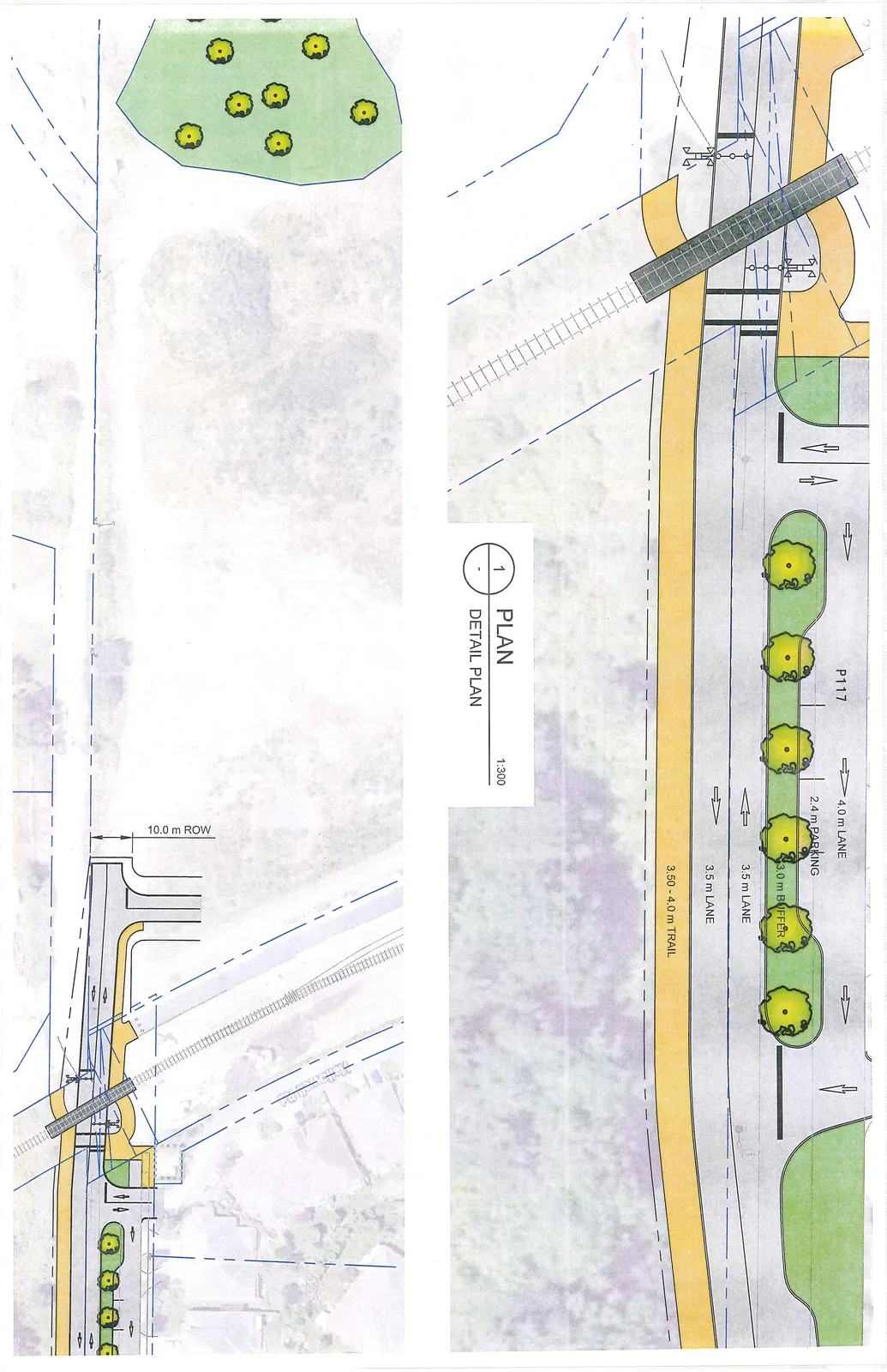
Engineering site plan diagrams. The top detail illustrates a road layout featuring a 4.0 m lane, 2.4 m parking, a 3.0 m treed buffer, two 3.5 m travel lanes, and a 3.50 - 4.0 m trail. A bridge structure is shown crossing a rail line. The bottom diagram provides a broader site view of the road and rail crossing, labeling a 10.0 m ROW (Right of Way).
Page 119–120

PLAN: FIRE TRUCK MOVEMENT

Scale: 1:200
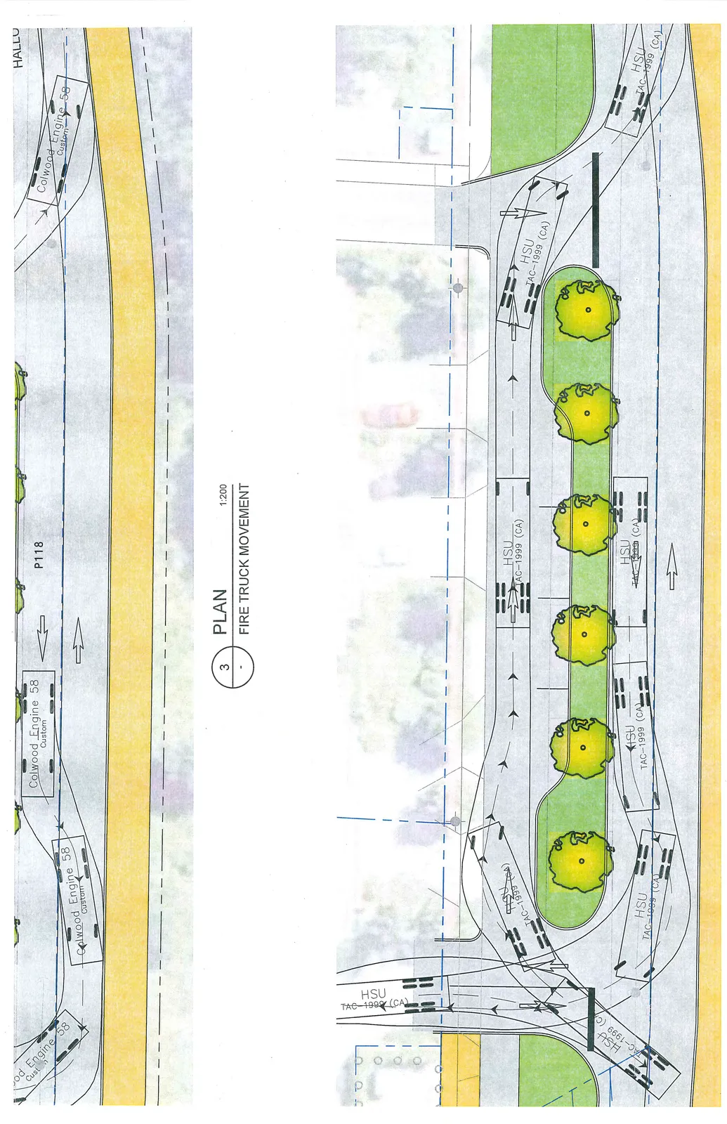
Vehicle swept path analysis diagrams. The top section shows the maneuverability of "Colwood Engine 58 Custom" along a road segment labeled P118. The bottom section depicts the turning paths for an "HSU TAC-1999 (CA)" vehicle through an intersection and adjacent to a treed parking island.
Page 119–120
Extracted from: 2015 06 23 Council Agenda