Appendix
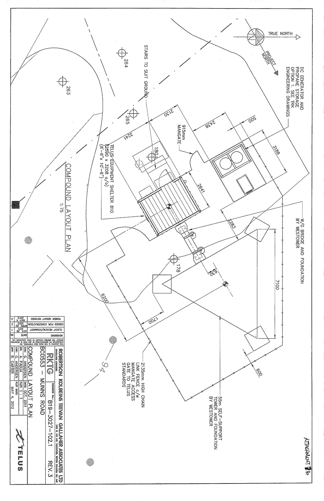
Attachment 7b: Compound Layout Plan
May 15, 2012Page 391 section
Close-up plan of the equipment shelter and backup generator enclosure within the compound.
2135mm high chain link fence
COMPOUND LAYOUT PLAN - BC0553 - MUNNS ROAD
Drawing Information
- Consulting Engineers: ROBERTSON KOLBEINS TEEVAN GALLAHER ASSOCIATES LTD (RKTG), 1985 W. 4th AVE. VANCOUVER, BRITISH COLUMBIA V6J 1M8
- Drawing No.: B19-3027-102.1
- Revision: 3
- Project: BC0553 - MUNNS ROAD
- Scale: 1:75
- Date: MAY 4, 2012
Revision History
| No. | Date | Revisions |
|---|---|---|
| 1 | OCT 26, 2011 | CLIENT REVIEW/COMMENT |
| 2 | APRIL 20, 2012 | ISSUED FOR CONSTRUCTION |
| 3 | MAY 4, 2012 | TOWER HEIGHT REVISED |
Site Plan Notes and Components
- DC Generator and Propane Storage: Option 1. See TRK Engineering Drawings.
- W/G Bridge and Foundation: By Westower.
- Tower: 55m Self-Support Tower and Foundation by Westower.
- Equipment Shelter: TELUS Equipment Shelter 810 (2590 x 3208 o/o) (8'-6" x 10'-6").
- Fencing: 2135mm high chain link fence c/w Mangate access gate to TELUS standards.
- Access: 915mm Mangate.
- Site Features: Stairs to suit ground.
- Reference Points: TRUE NORTH and PROJECT NORTH indicators; survey markers 263, 264, and 265.
Dimension Data (Millimeters)
- Generator/Propane Storage Area: 3188 x 2438, set back 500 from boundary.
- Fencing Segments: 7100, 6200, 1700, 630, 600.
- Shelter Positioning Dimensions: 2641, 2130, 3241, 2283.
- Other dimensions: 180, 178.
Approval and Administrative Details
- Engineer: G. Andersen (Date: OCT. 2011)
- Drawn By: A. Padua (Plot: 1:1)
- Checked By: G. Andersen
- Approved By: R. Carter (Plot Date: May 4, 2012)
Page 39
Extracted from: 2012 05 15 Council Agenda