This site is in beta — data may be incomplete and features are still being added.
Council Meeting/Documents/ATTACHMENT 3: Architectural Site Plans, Renderings and Zoning Summary
Appendix

ATTACHMENT 3: Architectural Site Plans, Renderings and Zoning Summary

November 7, 2023Pages 100–11818 sections

A set of architectural drawings including zoning summaries, precedents, conceptual renderings, site plans, parking plans, and shadow studies.

1. CALL TO ORDER (Mayor Tobias)
339 Island HighwayProposed Zone: RM-3300 parking stalls provided238 total suites

339 Island Highway

Boardwalk REIT
View Royal BC

Page 100–118

Zoning Bylaw Summary

General

  • Proposed Use: Mixed Residential
  • Proposed Zone: RM-3
  • Site Area: 132,147 sf / 130,558 sf (Pre and post road dedication)
  • Floor Area: 208,890 sf
  • FAR: 1.58 / 1.60
  • Site Coverage: 29%
  • Open Site Space: 71%
  • Impermeable Coverage: 46%
  • Max Height: 17.70m / 5 Storeys*

Parking

  • Required: 300 stalls
  • Provided: 300 stalls
  • Bicycle Stalls: 238

Setbacks

Yard RM-3 Zone Proposed
Front Yard Prince Robert Drive 7.5 m 8.1 m
Flanking Yard Island Highway 4.0 m 8.2 m
Side Yard Heddle Park 4.0 m 9.1 m
Rear Yard Fire Hall 7.0 m 7.0 m

Suite Summary

  • Studios: 05 suites (2%) | 450 - 575 sf
  • 1 Beds: 120 suites (50%) | 600 - 710 sf
  • 2 Beds: 108 suites (45%) | 845 - 905 sf
  • 3 Beds: 05 suites (2%) | 1,105 sf
  • Total: 238 Suites

* 6 storeys per BC Building Code
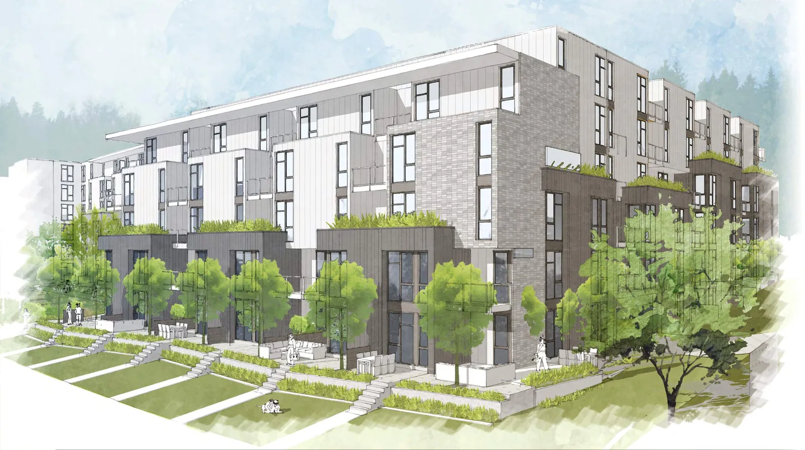
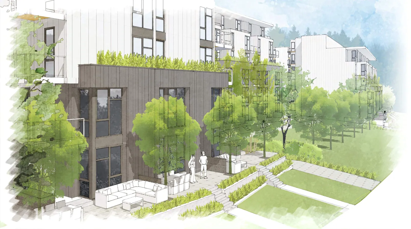
Architectural rendering of the proposed building complex from a low angle, showing multi-level residential units with green roofs and landscaped grounds.
Architectural rendering of the building frontage at street level, showing large windows, ground-floor units, and mature trees.
Page 100–118

Precedents

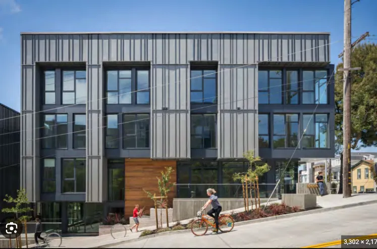
Photo of a contemporary multi-unit residential building with grey vertical siding and dark-framed windows.
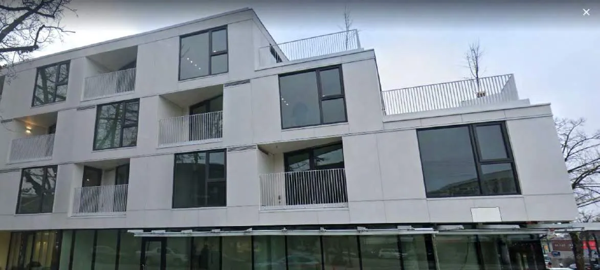
Photo of a modern apartment building with a white geometric facade and recessed balconies.
Photo of a building facade with grey cladding, wood accents, and large windows, with a person on a bicycle in front.
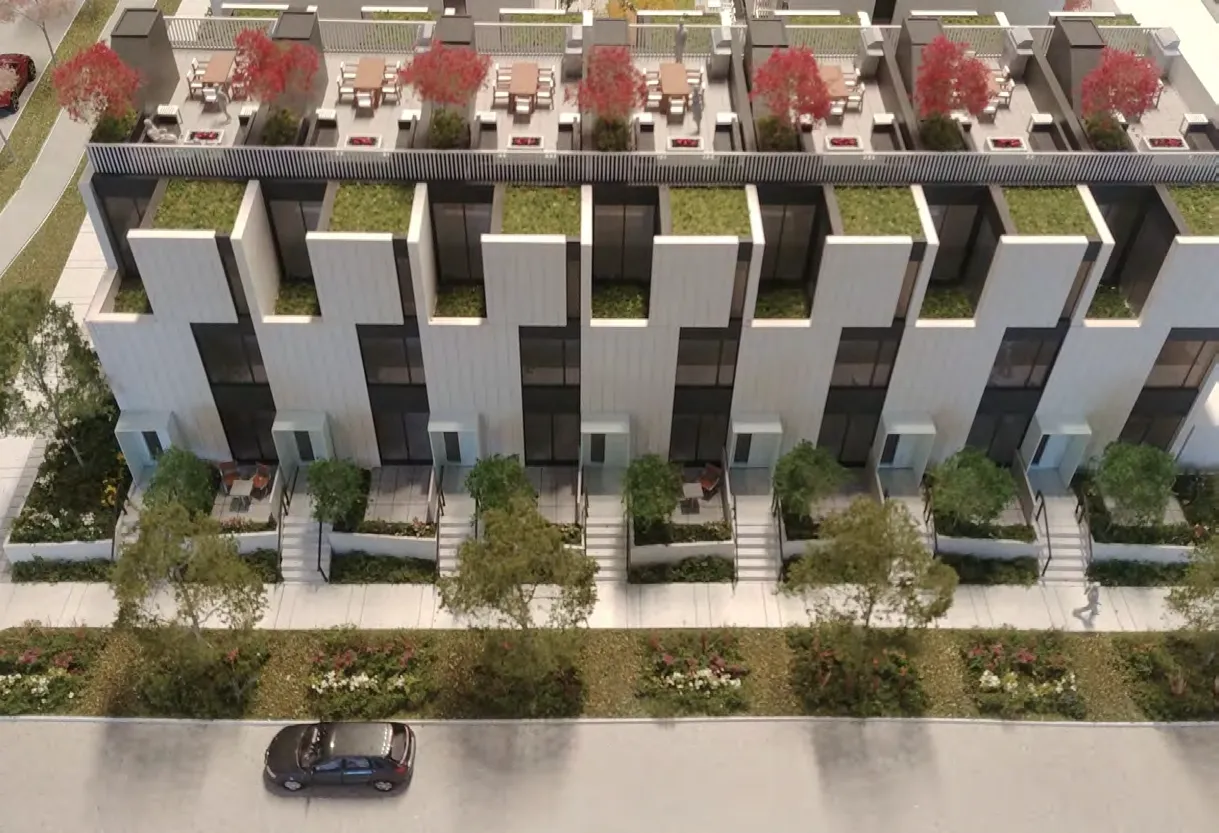
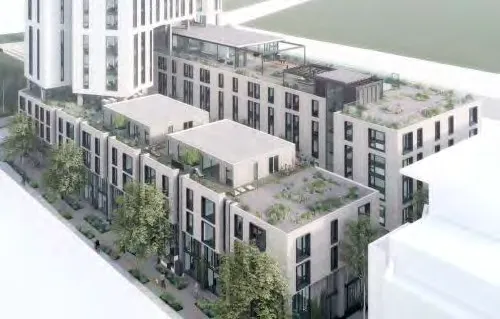
Architectural rendering of an aerial view of a building with multiple roof terraces and green spaces.
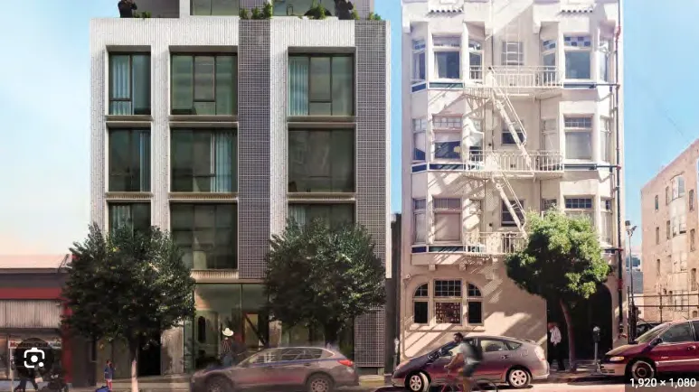
Photo of a modern multi-story residential building with light-colored facade next to an older white building.
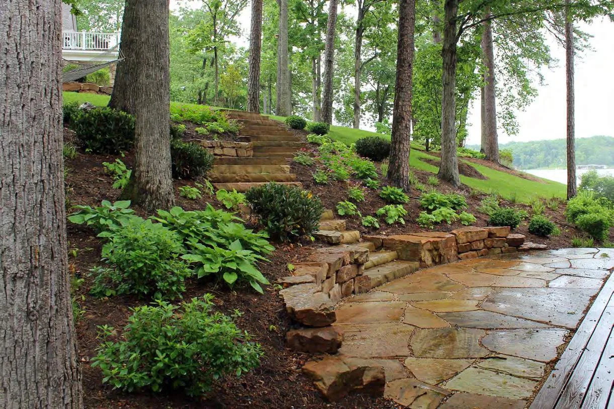
Photo of a landscaped stone path and steps in a wooded area.
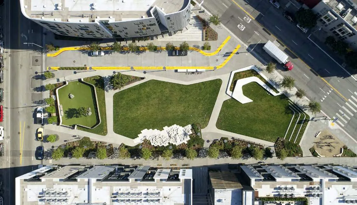
Aerial photo of a modern public plaza with geometric green spaces and walking paths.
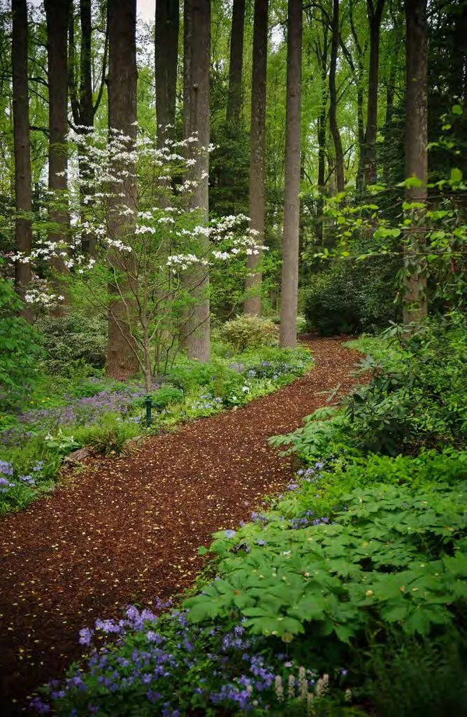
Photo of a bark-mulch path through a lush woodland garden with purple flowers.
Page 100–118

Design Concept

Maintain OCP Mixed Residential

  • Comply with OCP Mixed Residential designation
  • Reduced density to 1.6 FSR
  • No longer including commercial use as it was difficult to provide parking
  • Implements the OCP and additional residential supports existing and planned neighbourhood commercial
  • Site is +/- 400 m to commercial node at Helmcken & Island Highway
OCP Land Use Designation Map showing the project site and surrounding area.

Tree Preservation

  • Reduced footprint and increased depth of u/g parking - now with two full levels
  • Retaining more trees than previous concept: new site plan retains 146 trees (18 municipal trees, 125 onsite trees plus 3 trees with shared ownership)
  • 3x increase in amount retained trees
  • Replacing 43 removed trees at 2:1 ratio: full landscape plan at DP stage
Comparison maps showing tree preservation. Previous concept plan: 51 trees retained, 138 trees removed. New concept plan: 146 trees retained, 43 trees removed.

Building Siting

  • Avoided key tree preservation areas, with more retained tree canopy to support passive cooling, shade preservation, neighbourhood character
  • Increased setback from Island Highway: from 6 m to 8+ m, and reduced the frontage
  • Increased setback from Heddle Trail: from 8 m to 8.5+ m, and reduced the frontage
  • Reduced building lengths fronting neighbouring properties
Site plan diagrams showing building siting adjustments.

Public Benefits: Livability & Environment

  • Building to Step Code 3
  • Efficient and economic heating and cooling systems
  • Resident amenity spaces - indoor and outdoor with play structures, walking trails and gathering spaces
  • New buildings will help buffer neighbourhood from highway noise and will have high performance wall and window systems to reduce noise impacts for residents
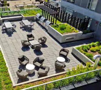
Detailed landscape plan showing amenities like play structures, woodland path, multi-use lawn, and naturalized planting.

Public Benefits: Transportation

  • New signalized traffic light at the intersection of Island Highway and Prince Robert at no cost to View Royal
  • New bus stop complete with a new bus shelter
  • Underground parking and bicycle parking meets bylaw requirements
  • Shared concerns about traffic “short-cutting” through the neighbourhood with View Royal staff

Quality Development

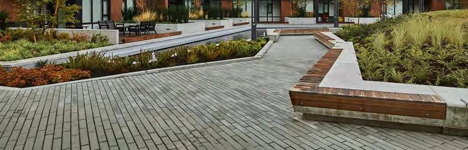
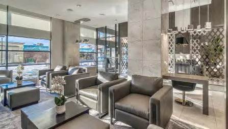
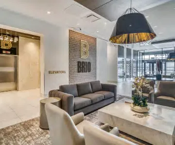
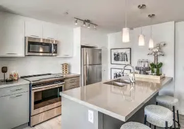
  • Examples of other Boardwalk developments
  • Developer to own and operate the building, with focus on high quality finishes and efficient systems
Page 100–118

Perspectives
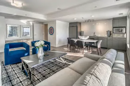
Aerial rendering of the proposed development integrated into the existing neighborhood, showing the two L-shaped building masses and surrounding trees.
Page 100–118

Site Plan

Detailed site plan (Scale 1:200) showing building footprints, setbacks, entry forecourt, outdoor amenity space, BBQ area, green space, child play structure, and woodland trails.
Page 100–118

P2 Parking Plan

P2 Parking Plan (Scale 1:200) showing parking layout, storage areas, and access ramps.
Page 100–118

P1 Parking Plan

P1 Parking Plan (Scale 1:200) showing parking layout, bike storage, garbage/mechanical rooms, and access.
Page 100–118

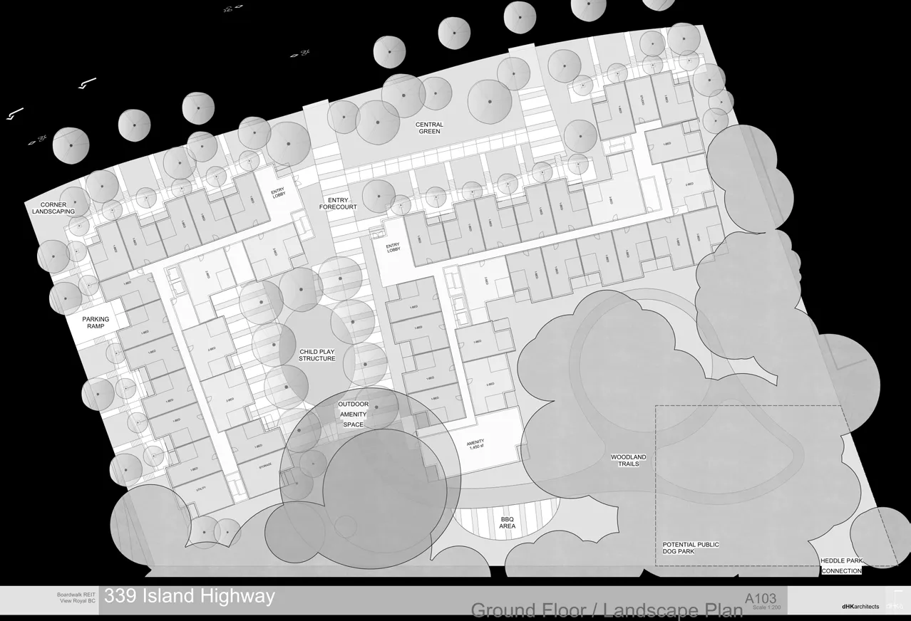
Ground Floor / Landscape Plan
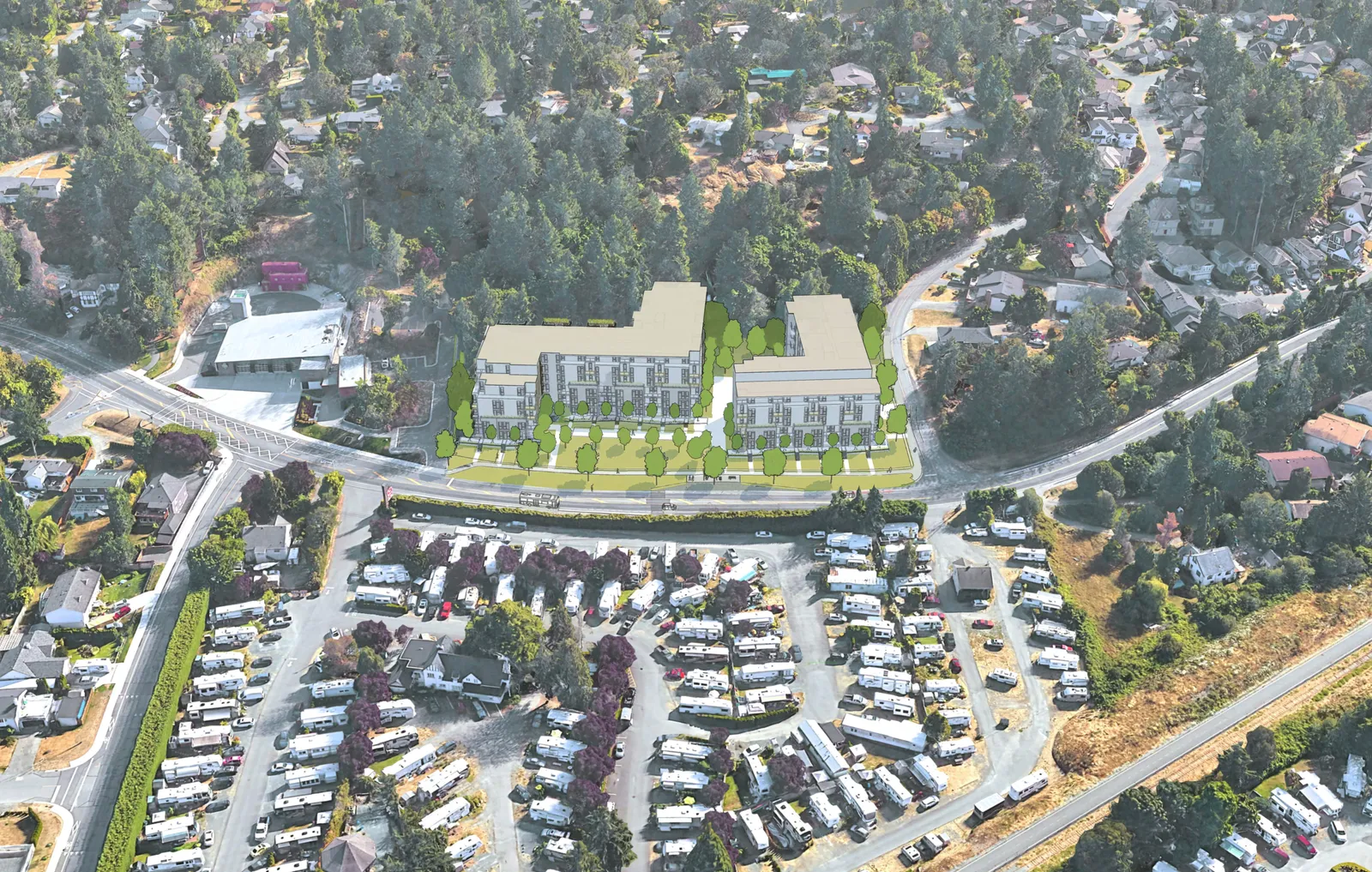
Combined ground floor plan and landscape plan (Scale 1:200) showing unit types (Studio, 1-Bed, 2-Bed, 3-Bed), amenities, and detailed landscaping.
Inset or related diagram of the ground floor / landscape plan in a simplified grayscale/black and white format.
Page 100–118

Typical Floor Plan

Typical floor plan (Scale 1:200) for floors 2-5, showing the distribution of various unit types across the two building wings.
Page 100–118

Top Floor Plan

Top floor plan (Scale 1:200) showing the reduced building footprint on the sixth level with roof areas.
Page 100–118

Emergency Access Plan

3.2.5.6. Access Route Design

  1. A portion of a roadway or yard provided as a required access route for fire department use shall: a) have a clear width not less than 6m, unless it can be shown that lesser widths are satisfactory, b) have a centre-line radius not less than 12 m, c) have an overhead clearance not less than 5m, d) have a change of gradient not more than 1 in 12.5 over a minimum distance of 15 m, e) be designed to support the expected loads imposed by firefighting equipment and be surfaced with concrete, asphalt or other material designed to permit accessibility under all climatic conditions, f) have turnaround facilities for any dead-end portion of the access route more than 90m long, and g) be connected with a public thoroughfare.
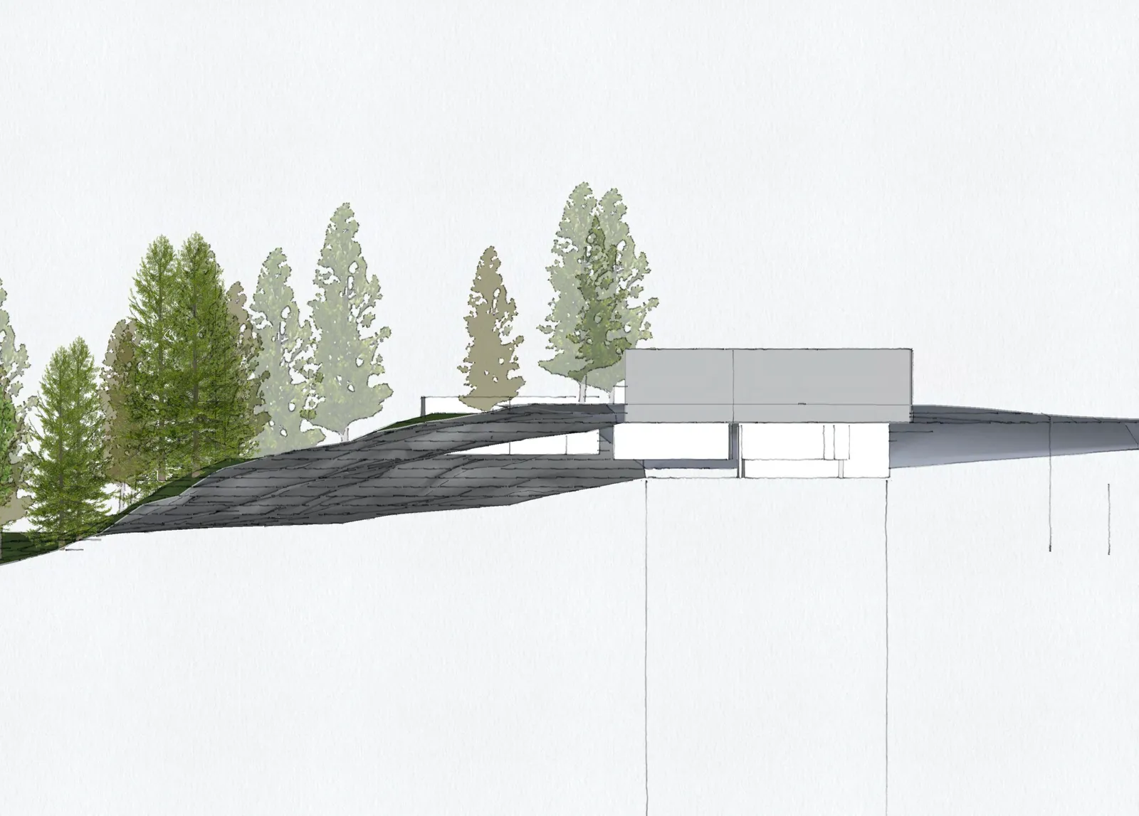
Emergency Access Plan (Scale 1:200) showing fire truck turning radii, slopes, and access routes.
Page 100–118

Site Access

Site Access plan (Scale 1:200) highlighting vehicle and pedestrian access points.
Page 100–118

Average Grade

Technical drawing showing topographic points and average grade calculations for the East and West Buildings.
Page 100–118

Impermeable vs. Permeable

  • 54% Permeable
  • 46% Impermeable
Plan highlighting permeable and impermeable site areas.
Page 100–118

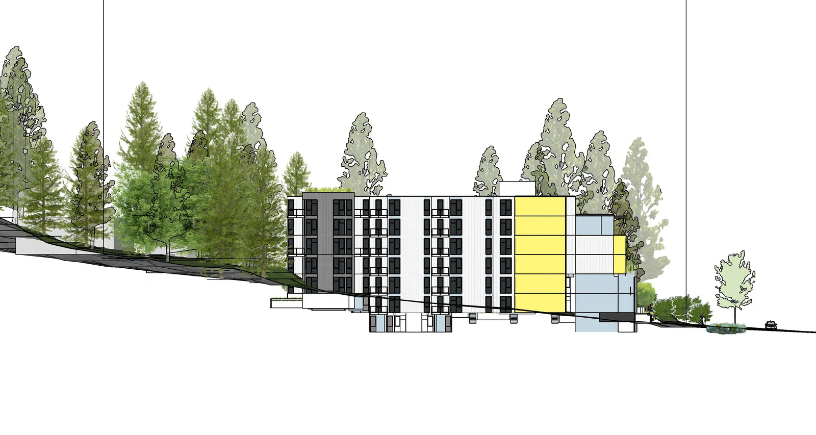
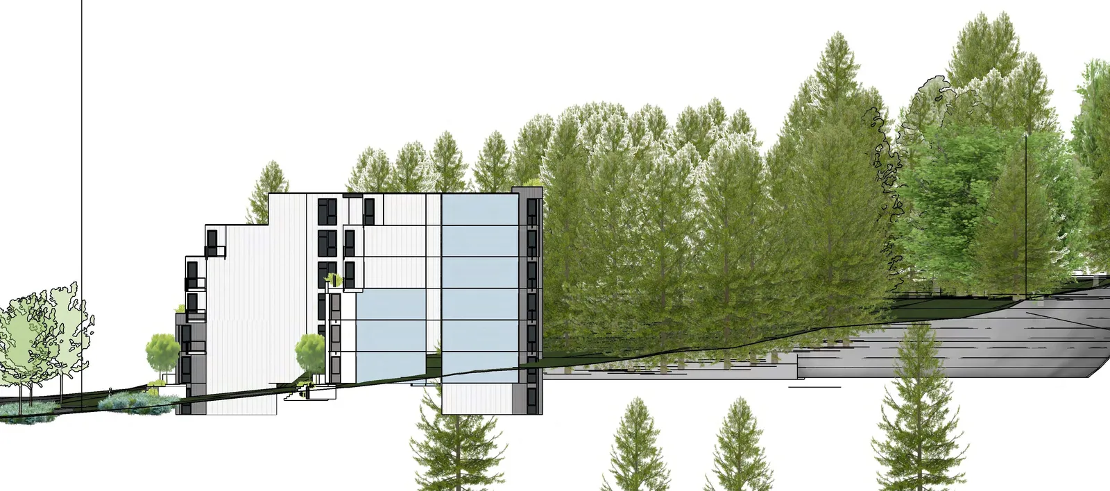
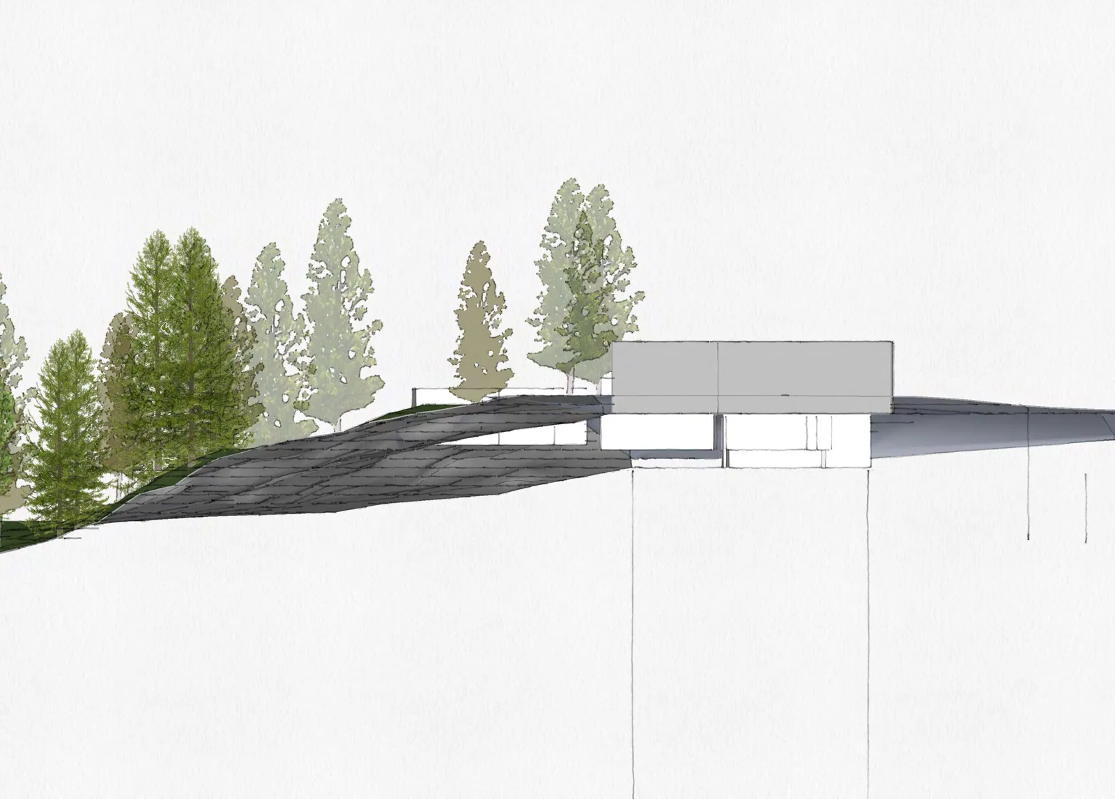
Site Sections

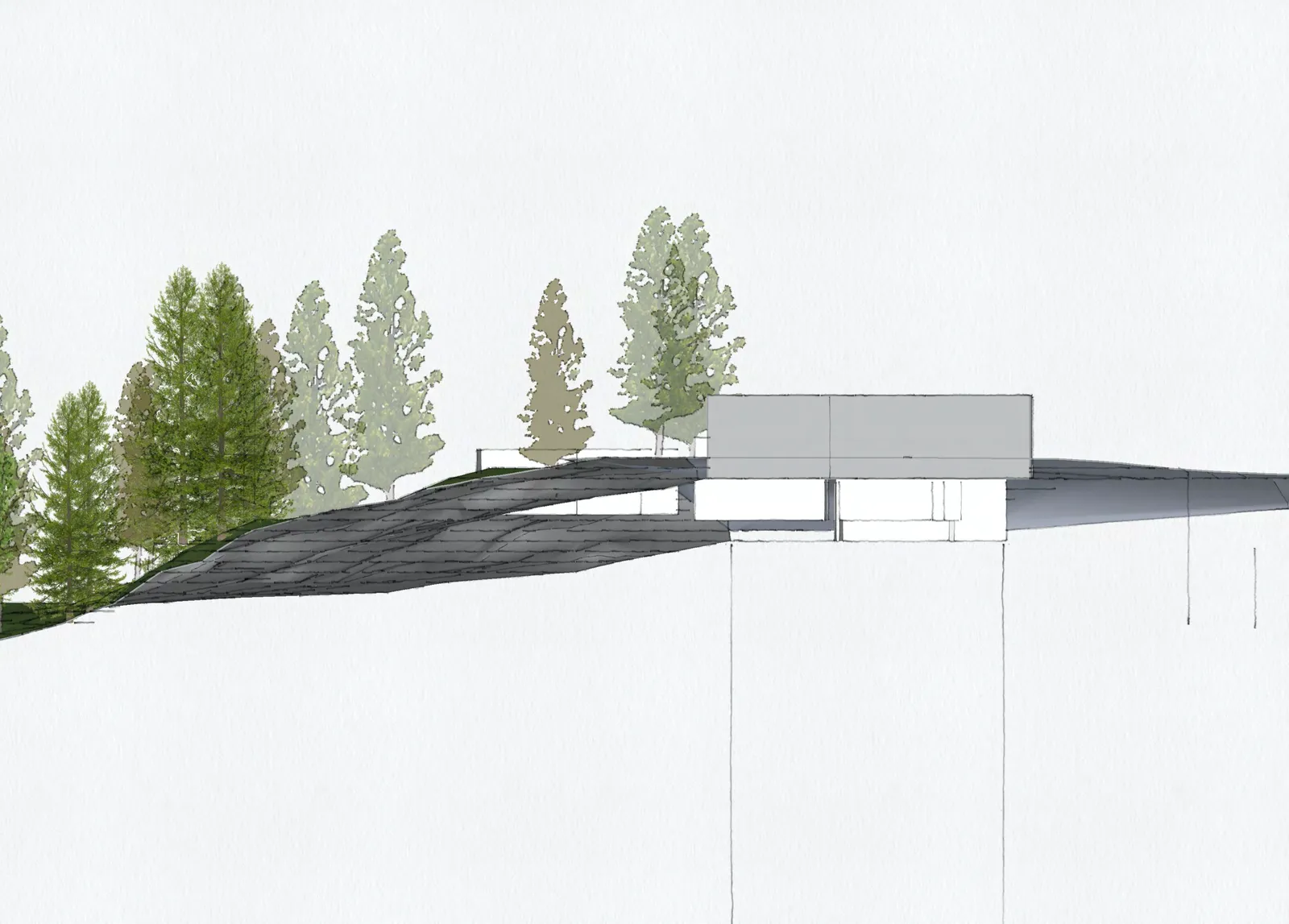
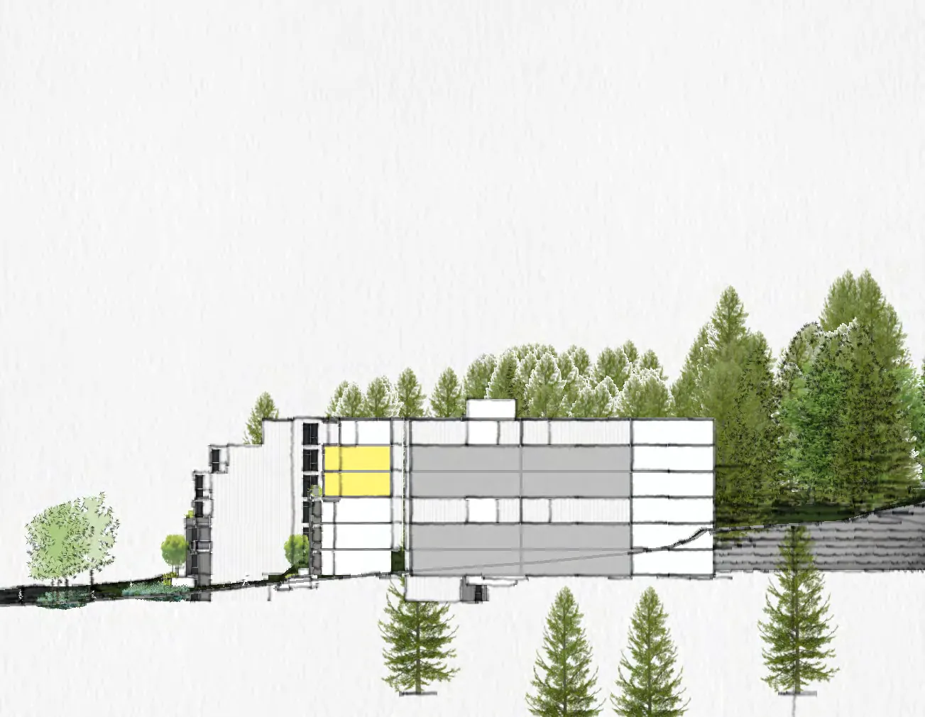
Longitudinal site sections 1 and 2 (Scale 1:200) showing building heights relative to the sloping terrain and average grade lines.
Key plan for site sections.
Page 100–118

Elevations

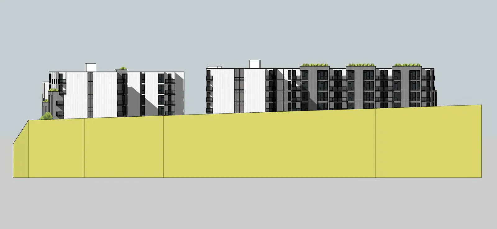
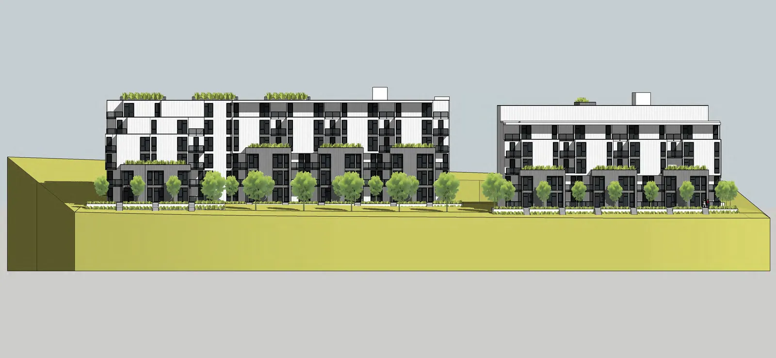
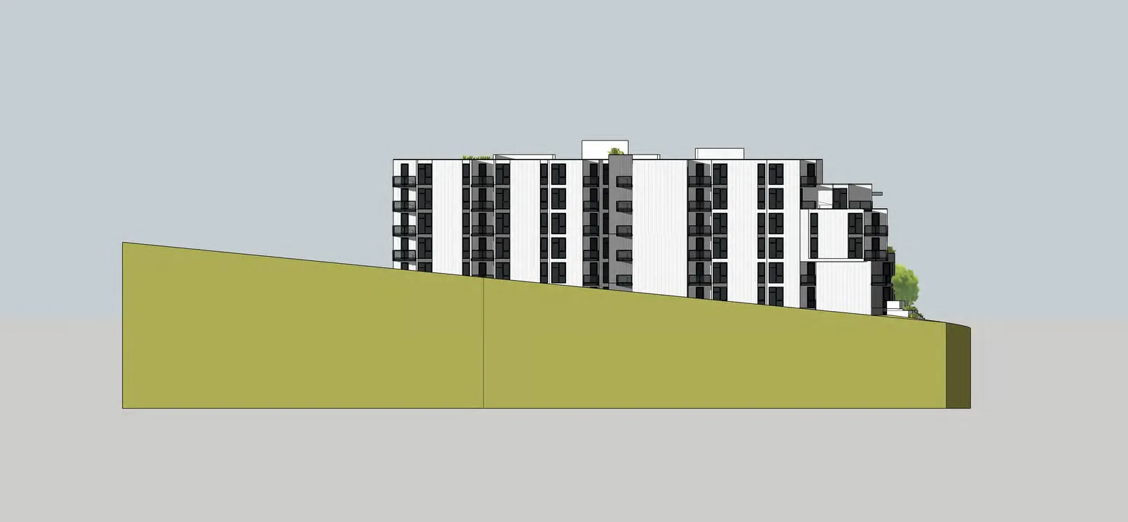
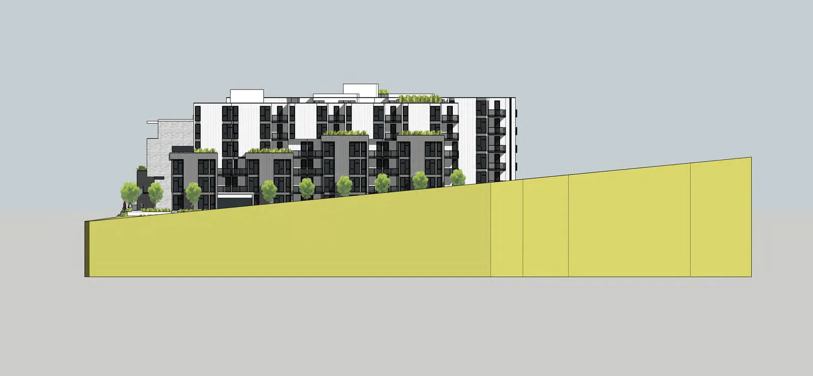
North and South architectural elevations (Scale 1:200) showing facade materials, balconies, and floor levels.
East and West architectural elevations (Scale 1:200).
Page 100–118

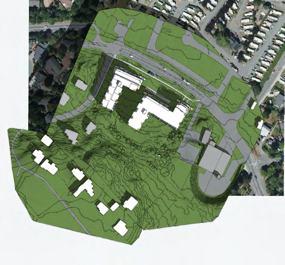
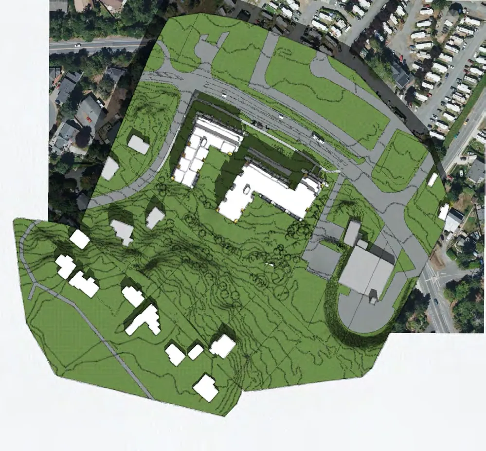
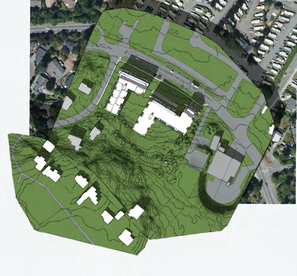
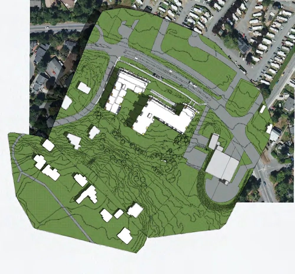
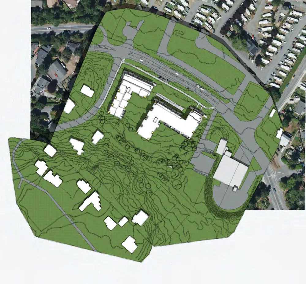
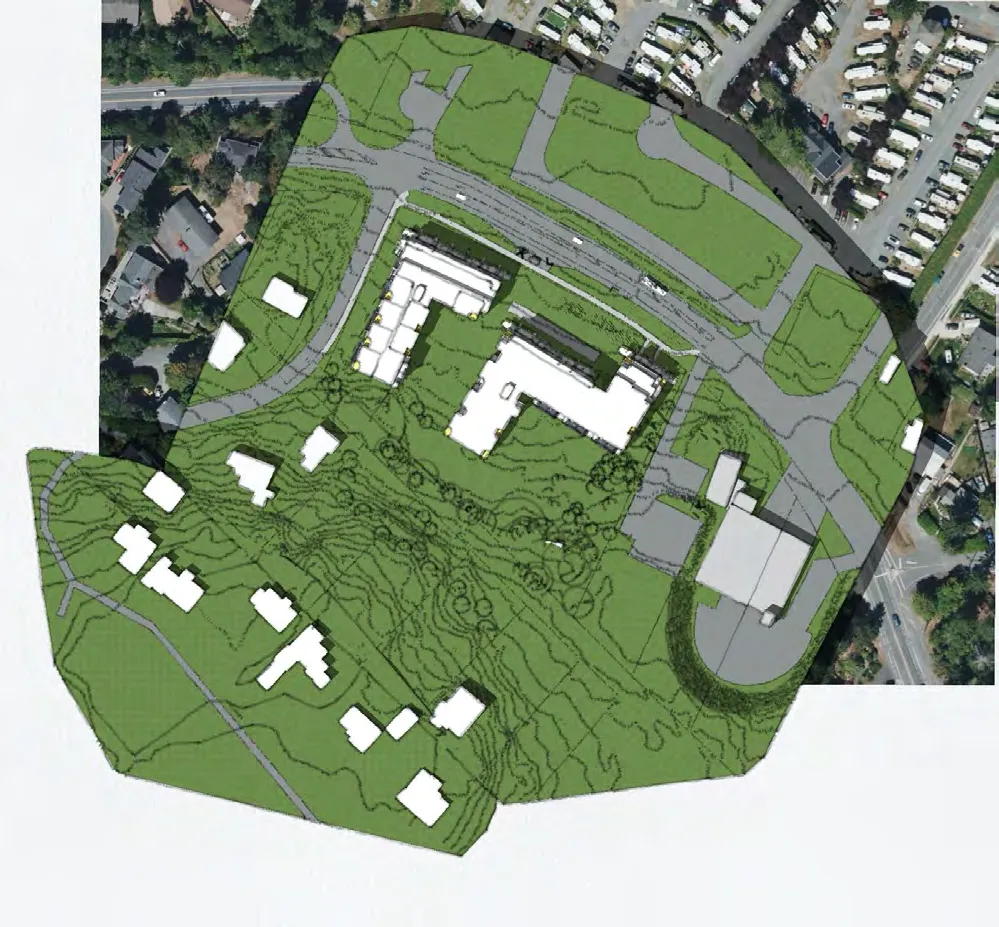
Shadow Studies

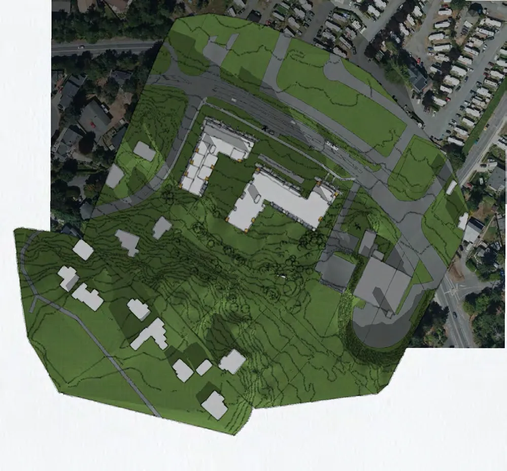
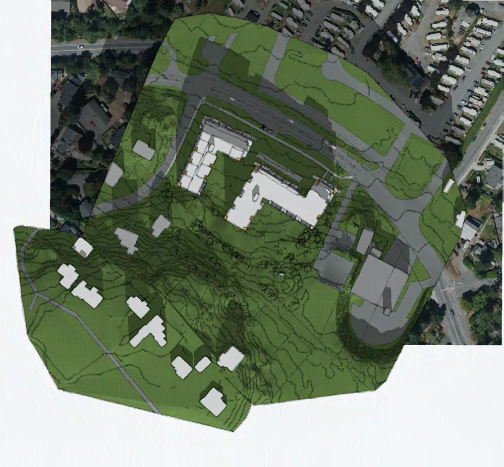
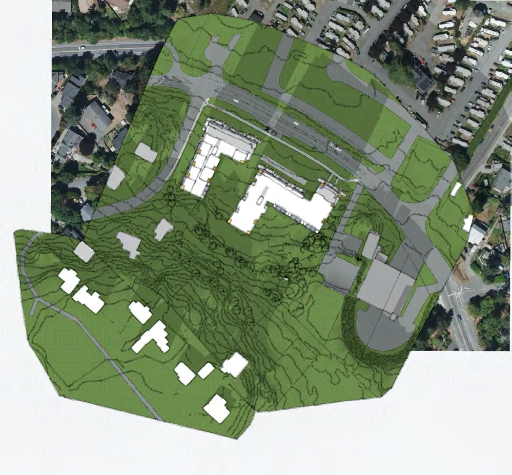
Shadow study - 21st March 10 am.
Shadow study - 21st March 12 pm.
Shadow study - 21st March 2 pm.
Shadow study - 21st June 10 am.
Shadow study - 21st June 12 pm.
Shadow study - 21st June 2 pm.
Shadow study - 21st Dec 10 am.
Shadow study - 21st Dec 12 pm.
Shadow study - 21st Dec 2 pm.
Page 100–118
Extracted from: 2023 11 07 Council Agenda - Agenda - Pdf