Attachment 17. Modifications to the Stormwater Master Plan & Interim SWMP/ESC Conditions Plan
Technical memorandum and sizing reports regarding changes to the stormwater management plan.
TECHNICAL MEMORANDUM
Issue Date: December 15, 2020 To: Jeff Chow, MCIP, RPP From: Ann Stephenson, P.Eng. Client: Limona Construction Project Name: West Park at Thetis Project No.: 2016-2253.000 File No.: 20162253.00.E.05.00 Subject: Modifications to the Stormwater Master Plan & Interim SWMP/ESC Conditions
1 INTRODUCTION
This memo is provided to clarify changes to the Stormwater Master Plan (SWMP) for the West Park at Thetis development in the Town of View Royal, and to confirm the mechanisms for stormwater treatment, and erosion and sediment control (ESC) for each phase moving forward.
2 SWMP
The (SWMP) for the West Park at Thetis project remains completely unchanged with respect to storage and attenuation of runoff. However, one change was made with respect to water quality treatment. In the original SWMP, dated September 2019, the plan was to provide a single, large Stormceptor™ for water quality treatment. However, as construction progressed it became apparent that such a deep excavation into the existing rock was not advisable and unnecessary.
The original Phase 1 Stormceptor™ was specified as a large EF10 to service the entire site. As the site was broken down into smaller phases, the decision was made to install treatment for the first phase only in January 2020. It was determined that installing a smaller Stormceptor™ to treat runoff from Phases 1 and 2, followed by another smaller Stormceptor™ for Phases 3 through 6 had a number of advantages. The main advantage being the reduction in excavation depth, but having multiple unit also provides additional safeguards for treatment and even emergency back-up for ESC during construction.
The first Stormceptor™ in Phase 1 is an EF6 model and was sized treat runoff from Phase 1 and 2, including the park area. It was sized using the online Imbrium software and sizing calculations are attached. With Phase 3 approaching it was discussed whether the next Stormceptor™ should be sized for the entire remaining development or just phase 3 and 5. Ultimately, the decision was made to size the Phase 3 unit to serve the entire remaining development. The Stormceptor™ in Phase 3 is an EF8 model, slightly larger that the phase 1 model due to the larger drainage area. It was also sized using the online Imbrium software and sizing calculations are attached. Both units were checked to confirm that they can pass both the anticipated water quality and peak flows, so they can be installed without a bypass.
3 INTERIM CONDITIONS
Stormwater management will be in place for all phases once the Phase 3 Stormceptor is installed. There will be some overland flow from the unfinished phases as work proceeds. However, the existing, fractured rock means there is very little water actually running off these areas. The majority of the water permeate the substrate as it did in the existing condition. There are perforated pipes at the base of rock cuts below Phases 4 to 6, designed to pick up any surface runoff from the rear south and west. These pipes directs water toward completed pipe network in Phases 1 and 2 and into the completed stormwater treatment system.
As the development continues, the proposed roadway through Phases 3 to 6 will be rough graded so the majority of surface water from this area will run along that corridor. As shown in the ESC plan, wheel washes and sumps will be constructed at the bottom of each phase to manage any sediment as work proceeds up the hill. The Stormceptors™ act as a secondary buffer to the system as they will capture any sediment that evades these precautions. Note that the portion of Phase 6 across from the Phase 4 condominium building will be cleared and rough graded with the Phase 4 work to allow for completion of the roadway.
4 CLOSURE
This report was prepared for Limona Construction and The Town of View Royal to clarify changes to the SWMP for the West Park at Thetis development, and to confirm the mechanisms for stormwater treatment, and ESC for each phase moving forward.
The services provided by Associated Engineering (B.C.) Ltd. in the preparation of this report were conducted in a manner consistent with the level of skill ordinarily exercised by members of the profession currently practicing under similar conditions. No other warranty expressed or implied is made.
Prepared by: Ann Stephenson, P.Eng. Civil Engineer
Reviewed by: Dennis Desjardins, AScT Project Manager
APPENDICES
Stormceptor™ Sizing Calculations
Phases 1 and 2 - Stormceptor EF Sizing Report
ESTIMATED NET ANNUAL SEDIMENT (TSS) LOAD REDUCTION STORMCEPTOR®
| Province: | British Columbia | Project Name: | Thetis Lake Apt PH1 |
| City: | View Royal | Project Number: | 2016-2331.010 |
| Nearest Rainfall Station: | VICTORIA | Designer Name: | Ann Stephenson |
| NCDC Rainfall Station Id: | 0300 | Designer Company: | Associated Engineering |
| Years of Rainfall Data: | 6 | Designer Email/Phone: | stephensona@ae.ca |
| Drainage Area (ha): | 1.09 | ||
| % Imperviousness: | 59.20 | ||
| Runoff Coefficient 'c': | 0.65 |
| Particle Size Distribution: | CA ETV |
|---|---|
| Target TSS Removal (%): | 60.0 |
| Require Hydrocarbon Spill Capture? | No |
| Upstream Flow Control? | No |
Net Annual Sediment (TSS) Load Reduction Sizing Summary
| Stormceptor Model | TSS Removal Provided (%) |
|---|---|
| EF4 | 54 |
| EF6 | 61 |
| EF8 | 64 |
| EF10 | 66 |
| EF12 | 67 |
Recommended Stormceptor EF Model: EF6 Estimated Net Annual Sediment (TSS) Load Reduction (%): 61
THIRD-PARTY TESTING AND VERIFICATION Stormceptor® EF and Stormceptor® EFO are the latest evolutions in the Stormceptor® oil-grit separator (OGS) technology series, and are designed to remove a wide variety of pollutants from stormwater and snowmelt runoff. These technologies have been third-party tested in accordance with the Canadian ETV Procedure for Laboratory Testing of Oil-Grit Separators and performance has been third-party verified in accordance with the ISO 14034 Environmental Technology Verification (ETV) protocol.
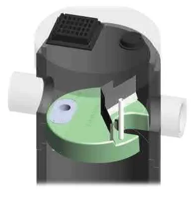
PERFORMANCE Stormceptor® EF and EFO remove stormwater pollutants through gravity separation and floatation, and feature a patent-pending design that generates positive removal of total suspended solids (TSS) throughout each storm event, including high-intensity storms. Captured pollutants include sediment, free oils, and sediment-bound pollutants such as nutrients, heavy metals, and petroleum hydrocarbons. Stormceptor is sized to remove a high level of TSS from the frequent rainfall events that contribute the vast majority of annual runoff volume and pollutant load. The technology incorporates an internal bypass to convey excessive stormwater flows from high-intensity storms through the device without resuspension and washout (scour) of previously captured pollutants. Proper routine maintenance ensures high pollutant removal performance and protection of downstream waterways.
PARTICLE SIZE DISTRIBUTION (PSD) The Canadian ETV PSD shown in the table below was used, or in part, for this sizing.
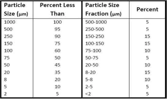
| Particle Size (µm) | Percent Less Than | Particle Size Fraction (µm) | Percent |
|---|---|---|---|
| 1000 | 100 | 500-1000 | 5 |
| 500 | 95 | 250-500 | 5 |
| 250 | 90 | 150-250 | 15 |
| 150 | 75 | 100-150 | 15 |
| 100 | 60 | 75-100 | 10 |
| 75 | 50 | 50-75 | 5 |
| 50 | 45 | 20-50 | 10 |
| 20 | 35 | 8-20 | 15 |
| 8 | 20 | 5-8 | 10 |
| 5 | 10 | 2-5 | 5 |
| 2 | 5 | <2 | 5 |
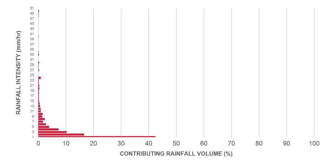
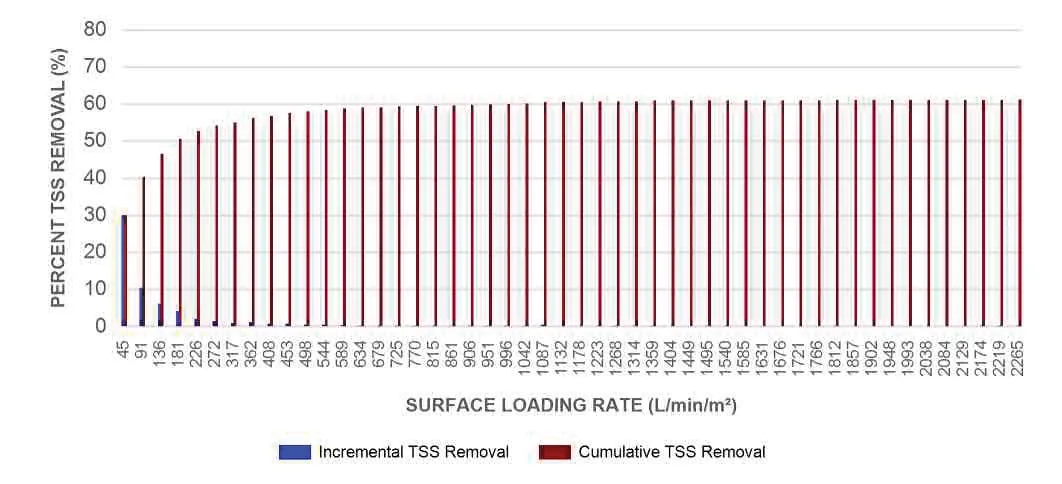
Phases 1 and 2 - Sizing Table
| Rainfall Intensity (mm/hr) | Percent Rainfall Volume (%) | Cumulative Rainfall Volume (%) | Flow Rate (L/s) | Flow Rate (L/min) | Surface Loading Rate (L/min/m²) | Removal Efficiency (%) | Incremental Removal (%) | Cumulative Removal (%) |
|---|---|---|---|---|---|---|---|---|
| 1 | 42.5 | 42.5 | 1.99 | 119.0 | 45.0 | 70 | 29.9 | 29.9 |
| 2 | 16.6 | 59.1 | 3.97 | 238.0 | 91.0 | 63 | 10.5 | 40.4 |
| 3 | 10.3 | 69.4 | 5.96 | 357.0 | 136.0 | 60 | 6.2 | 46.6 |
| 4 | 7.3 | 76.7 | 7.94 | 476.0 | 181.0 | 56 | 4.1 | 50.6 |
| 5 | 3.9 | 80.6 | 9.93 | 596.0 | 226.0 | 53 | 2.1 | 52.7 |
| 6 | 2.8 | 83.4 | 11.91 | 715.0 | 272.0 | 52 | 1.5 | 54.2 |
| 7 | 1.7 | 85.1 | 13.90 | 834.0 | 317.0 | 51 | 0.9 | 55.0 |
| 8 | 2.3 | 87.4 | 15.88 | 953.0 | 362.0 | 49 | 1.1 | 56.2 |
| 9 | 1.4 | 88.8 | 17.87 | 1072.0 | 408.0 | 48 | 0.7 | 56.8 |
| 10 | 1.6 | 90.4 | 19.85 | 1191.0 | 453.0 | 48 | 0.8 | 57.6 |
| 11 | 0.9 | 91.3 | 21.84 | 1310.0 | 498.0 | 47 | 0.4 | 58.0 |
| 12 | 0.9 | 92.2 | 23.82 | 1429.0 | 544.0 | 47 | 0.4 | 58.4 |
| 13 | 0.7 | 92.9 | 25.81 | 1549.0 | 589.0 | 46 | 0.3 | 58.8 |
| 14 | 0.5 | 93.4 | 27.80 | 1668.0 | 634.0 | 46 | 0.2 | 59.0 |
| 15 | 0.3 | 93.7 | 29.78 | 1787.0 | 679.0 | 46 | 0.1 | 59.1 |
| 16 | 0.3 | 94.0 | 31.77 | 1906.0 | 725.0 | 45 | 0.1 | 59.3 |
| 17 | 0.2 | 94.2 | 33.75 | 2025.0 | 770.0 | 45 | 0.1 | 59.4 |
| 18 | 0.3 | 94.5 | 35.74 | 2144.0 | 815.0 | 45 | 0.1 | 59.5 |
| 19 | 0.2 | 94.7 | 37.72 | 2263.0 | 861.0 | 45 | 0.1 | 59.6 |
| 20 | 0.4 | 95.1 | 39.71 | 2382.0 | 906.0 | 45 | 0.2 | 59.8 |
| 21 | 0.4 | 95.5 | 41.69 | 2502.0 | 951.0 | 44 | 0.2 | 59.9 |
| 22 | 0.2 | 95.7 | 43.68 | 2621.0 | 996.0 | 44 | 0.1 | 60.0 |
| 23 | 0.2 | 95.9 | 45.66 | 2740.0 | 1042.0 | 45 | 0.1 | 60.1 |
| 24 | 0.9 | 96.8 | 47.65 | 2859.0 | 1087.0 | 45 | 0.4 | 60.5 |
| 25 | 0.0 | 96.8 | 49.63 | 2978.0 | 1132.0 | 46 | 0.0 | 60.5 |
| 26 | 0.0 | 96.8 | 51.62 | 3097.0 | 1178.0 | 46 | 0.0 | 60.5 |
| 27 | 0.3 | 97.1 | 53.61 | 3216.0 | 1223.0 | 47 | 0.1 | 60.7 |
| 28 | 0.1 | 97.2 | 55.59 | 3335.0 | 1268.0 | 47 | 0.0 | 60.7 |
| 29 | 0.1 | 97.3 | 57.58 | 3455.0 | 1314.0 | 48 | 0.0 | 60.7 |
| 30 | 0.3 | 97.6 | 59.56 | 3574.0 | 1359.0 | 48 | 0.1 | 60.9 |
| 31 | 0.0 | 97.6 | 61.55 | 3693.0 | 1404.0 | 49 | 0.0 | 60.9 |
| 32 | 0.0 | 97.6 | 63.53 | 3812.0 | 1449.0 | 47 | 0.0 | 60.9 |
| 33 | 0.2 | 97.8 | 65.52 | 3931.0 | 1495.0 | 46 | 0.1 | 61.0 |
| 34 | 0.1 | 97.9 | 67.50 | 4050.0 | 1540.0 | 45 | 0.0 | 61.0 |
| 35 | 0.0 | 97.9 | 69.49 | 4169.0 | 1585.0 | 43 | 0.0 | 61.0 |
| 36 | 0.0 | 97.9 | 71.47 | 4288.0 | 1631.0 | 42 | 0.0 | 61.0 |
| 37 | 0.0 | 97.9 | 73.46 | 4408.0 | 1676.0 | 41 | 0.0 | 61.0 |
| 38 | 0.0 | 97.9 | 75.44 | 4527.0 | 1721.0 | 40 | 0.0 | 61.0 |
| 39 | 0.0 | 97.9 | 77.43 | 4646.0 | 1766.0 | 39 | 0.0 | 61.0 |
| 40 | 0.1 | 98.0 | 79.42 | 4765.0 | 1812.0 | 38 | 0.0 | 61.1 |
| 41 | 0.0 | 98.0 | 81.40 | 4884.0 | 1857.0 | 37 | 0.0 | 61.1 |
| 42 | 0.0 | 98.0 | 83.39 | 5003.0 | 1902.0 | 36 | 0.0 | 61.1 |
| 43 | 0.0 | 98.0 | 85.37 | 5122.0 | 1948.0 | 35 | 0.0 | 61.1 |
| 44 | 0.0 | 98.0 | 87.36 | 5241.0 | 1993.0 | 34 | 0.0 | 61.1 |
| 45 | 0.0 | 98.0 | 89.34 | 5361.0 | 2038.0 | 34 | 0.0 | 61.1 |
| 46 | 0.0 | 98.0 | 91.33 | 5480.0 | 2084.0 | 33 | 0.0 | 61.1 |
| 47 | 0.0 | 98.0 | 93.31 | 5599.0 | 2129.0 | 32 | 0.0 | 61.1 |
| 48 | 0.1 | 98.1 | 95.30 | 5718.0 | 2174.0 | 32 | 0.0 | 61.1 |
| 49 | 0.1 | 98.2 | 97.28 | 5837.0 | 2219.0 | 31 | 0.0 | 61.1 |
| 50 | 0.2 | 98.4 | 99.27 | 5956.0 | 2265.0 | 30 | 0.1 | 61.2 |
Estimated Net Annual Sediment (TSS) Load Reduction = 61%
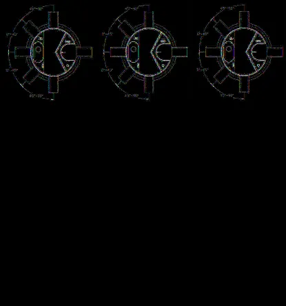
Maximum Pipe Diameter / Peak Conveyance
| Stormceptor EF / EFO | Model Diameter (m) | Model Diameter (ft) | Min Angle Inlet / Outlet Pipes | Max Inlet Pipe Diameter (mm) | Max Inlet Pipe Diameter (in) | Max Outlet Pipe Diameter (mm) | Max Outlet Pipe Diameter (in) | Peak Conveyance Flow Rate (L/s) | Peak Conveyance Flow Rate (cfs) |
|---|---|---|---|---|---|---|---|---|---|
| EF4 / EFO4 | 1.2 | 4 | 90 | 609 | 24 | 609 | 24 | 425 | 15 |
| EF6 / EFO6 | 1.8 | 6 | 90 | 914 | 36 | 914 | 36 | 990 | 35 |
| EF8 / EFO8 | 2.4 | 8 | 90 | 1219 | 48 | 1219 | 48 | 1700 | 60 |
| EF10 / EFO10 | 3.0 | 10 | 90 | 1828 | 72 | 1828 | 72 | 2830 | 100 |
| EF12 / EFO12 | 3.6 | 12 | 90 | 1828 | 72 | 1828 | 72 | 2830 | 100 |
SCOUR PREVENTION AND ONLINE CONFIGURATION Stormceptor® EF and EFO feature an internal bypass and superior scour prevention technology that have been demonstrated in third-party testing according to the scour testing provisions of the Canadian ETV Procedure for Laboratory Testing of Oil-Grit Separators.
DESIGN FLEXIBILITY Stormceptor® EF and EFO offers design flexibility in one simplified platform, accepting stormwater flow from a single inlet pipe or multiple inlet pipes, and/or surface runoff through an inlet grate.
OIL CAPTURE AND RETENTION While Stormceptor® EF will capture and retain oil from dry weather spills and low intensity runoff, Stormceptor® EFO has demonstrated superior oil capture and greater than 99% oil retention in third-party testing according to the light liquid re-entrainment testing provisions of the Canadian ETV Procedure for Laboratory Testing of Oil-Grit Separators.
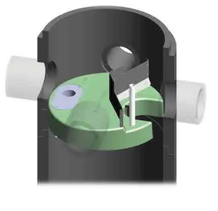
INLET-TO-OUTLET DROP Elevation differential between inlet and outlet pipe inverts is dictated by the angle at which the inlet pipe(s) enters the unit.
- 0° - 45°: The inlet pipe is 1-inch (25mm) higher than the outlet pipe.
- 45° - 90°: The inlet pipe is 2-inches (50mm) higher than the outlet pipe.
HEAD LOSS The head loss through Stormceptor EF is similar to that of a 60-degree bend structure. The applicable K value for calculating minor losses through the unit is 1.1. For submerged conditions the applicable K value is 3.0.
Pollutant Capacity
| Stormceptor EF / EFO | Model Diameter (m) | Model Diameter (ft) | Depth (Outlet Pipe Invert to Sump Floor) (m) | Depth (Outlet Pipe Invert to Sump Floor) (ft) | Oil Volume (L) | Oil Volume (Gal) | Recommended Sediment Maintenance Depth* (mm) | Recommended Sediment Maintenance Depth* (in) | Maximum Sediment Volume* (L) | Maximum Sediment Volume* (ft³) | Maximum Sediment Mass** (kg) | Maximum Sediment Mass** (lb) |
|---|---|---|---|---|---|---|---|---|---|---|---|---|
| EF4 / EFO4 | 1.2 | 4 | 1.52 | 5.0 | 197 | 52 | 203 | 8 | 1190 | 42 | 1904 | 5250 |
| EF6 / EFO6 | 1.8 | 6 | 1.93 | 6.3 | 348 | 92 | 305 | 12 | 3470 | 123 | 5552 | 15375 |
| EF8 / EFO8 | 2.4 | 8 | 2.59 | 8.5 | 545 | 144 | 610 | 24 | 8780 | 310 | 14048 | 38750 |
| EF10 / EFO10 | 3.0 | 10 | 3.25 | 10.7 | 874 | 231 | 610 | 24 | 17790 | 628 | 28464 | 78500 |
| EF12 / EFO12 | 3.6 | 12 | 3.89 | 12.8 | 1219 | 322 | 610 | 24 | 31220 | 1103 | 49952 | 137875 |
* Increased sump depth may be added to increase sediment storage capacity. ** Average density of wet packed sediment in sump = 1.6 kg/L (100 lb/ft³)
Table of TSS Removal vs Surface Loading Rate Based on Third-Party Test Results (Stormceptor® EF)
| SLR (L/min/m²) | TSS % REMOVAL | SLR (L/min/m²) | TSS % REMOVAL | SLR (L/min/m²) | TSS % REMOVAL | SLR (L/min/m²) | TSS % REMOVAL |
|---|---|---|---|---|---|---|---|
| 1 | 70 | 660 | 46 | 1320 | 48 | 1980 | 35 |
| 30 | 70 | 690 | 46 | 1350 | 48 | 2010 | 34 |
| 60 | 67 | 720 | 45 | 1380 | 49 | 2040 | 34 |
| 90 | 63 | 750 | 45 | 1410 | 49 | 2070 | 33 |
| 120 | 61 | 780 | 45 | 1440 | 48 | 2100 | 33 |
| 150 | 58 | 810 | 45 | 1470 | 47 | 2130 | 32 |
| 180 | 56 | 840 | 45 | 1500 | 46 | 2160 | 32 |
| 210 | 54 | 870 | 45 | 1530 | 45 | 2190 | 31 |
| 240 | 53 | 900 | 45 | 1560 | 44 | 2220 | 31 |
| 270 | 52 | 930 | 44 | 1590 | 43 | 2250 | 30 |
| 300 | 51 | 960 | 44 | 1620 | 42 | 2280 | 30 |
| 330 | 50 | 990 | 44 | 1650 | 42 | 2310 | 30 |
| 360 | 49 | 1020 | 44 | 1680 | 41 | 2340 | 29 |
| 390 | 48 | 1050 | 45 | 1710 | 40 | 2370 | 29 |
| 420 | 48 | 1080 | 45 | 1740 | 39 | 2400 | 29 |
| 450 | 48 | 1110 | 45 | 1770 | 39 | 2430 | 28 |
| 480 | 47 | 1140 | 46 | 1800 | 38 | 2460 | 28 |
| 510 | 47 | 1170 | 46 | 1830 | 37 | 2490 | 28 |
| 540 | 47 | 1200 | 47 | 1860 | 37 | 2520 | 27 |
| 570 | 46 | 1230 | 47 | 1890 | 36 | 2550 | 27 |
| 600 | 46 | 1260 | 47 | 1920 | 36 | 2580 | 27 |
| 630 | 46 | 1290 | 48 | 1950 | 35 |
Phases 3 to 6 - Stormceptor EF Sizing Report
ESTIMATED NET ANNUAL SEDIMENT (TSS) LOAD REDUCTION STORMCEPTOR® Report Date: 09/18/2020
| Province: | British Columbia | Project Name: | West Park at Thetis Phase Three |
| City: | Victoria | Project Number: | 33206 |
| Nearest Rainfall Station: | VICTORIA | Designer Name: | Eric Finney |
| NCDC Rainfall Station Id: | 0300 | Designer Company: | Associated Engineering |
| Years of Rainfall Data: | 6 | Designer Email: | finneye@ae.ca |
| Designer Phone: | 604-293-1411 | ||
| Site Name: | All phases above Phase 1 and 2 | ||
| Drainage Area (ha): | 1.565 | ||
| Runoff Coefficient 'c': | 0.68 |
| Particle Size Distribution: | CA ETV |
|---|---|
| Target TSS Removal (%): | 60.0 |
| Oil / Fuel Spill Risk Site? | No |
| Upstream Flow Control? | No |
Net Annual Sediment (TSS) Load Reduction Sizing Summary
| Stormceptor Model | TSS Removal Provided (%) |
|---|---|
| EF4 | 50 |
| EF6 | 58 |
| EF8 | 62 |
| EF10 | 65 |
| EF12 | 66 |
Recommended Stormceptor EF Model: EF8 Estimated Net Annual Sediment (TSS) Load Reduction (%): 62
THIRD-PARTY TESTING AND VERIFICATION (Section content is identical to Phases 1 and 2 report)
PERFORMANCE (Section content is identical to Phases 1 and 2 report)
PARTICLE SIZE DISTRIBUTION (PSD)
(Table data is identical to Phases 1 and 2 report)
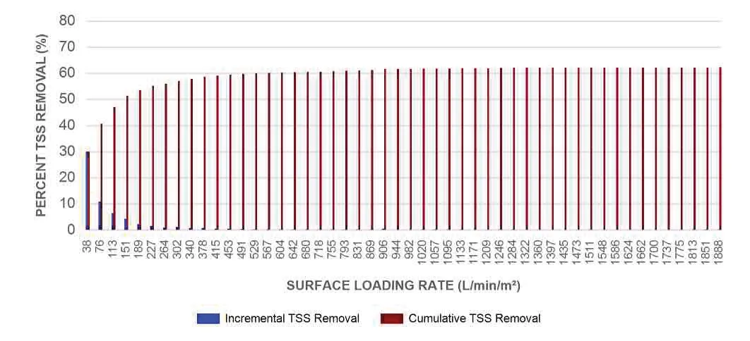
Phases 3 to 6 - Sizing Table
| Rainfall Intensity (mm/hr) | Percent Rainfall Volume (%) | Cumulative Rainfall Volume (%) | Flow Rate (L/s) | Flow Rate (L/min) | Surface Loading Rate (L/min/m²) | Removal Efficiency (%) | Incremental Removal (%) | Cumulative Removal (%) |
|---|---|---|---|---|---|---|---|---|
| 1 | 42.5 | 42.5 | 2.96 | 178.0 | 38.0 | 70 | 29.9 | 29.9 |
| 2 | 16.6 | 59.1 | 5.92 | 355.0 | 76.0 | 66 | 10.9 | 40.8 |
| 3 | 10.3 | 69.4 | 8.88 | 533.0 | 113.0 | 62 | 6.3 | 47.1 |
| 4 | 7.3 | 76.7 | 11.83 | 710.0 | 151.0 | 58 | 4.2 | 51.4 |
| 5 | 3.9 | 80.6 | 14.79 | 888.0 | 189.0 | 56 | 2.2 | 53.6 |
| 6 | 2.8 | 83.4 | 17.75 | 1065.0 | 227.0 | 53 | 1.5 | 55.1 |
| 7 | 1.7 | 85.1 | 20.71 | 1243.0 | 264.0 | 52 | 0.9 | 55.9 |
| 8 | 2.3 | 87.4 | 23.67 | 1420.0 | 302.0 | 51 | 1.2 | 57.1 |
| 9 | 1.4 | 88.8 | 26.63 | 1598.0 | 340.0 | 50 | 0.7 | 57.8 |
| 10 | 1.6 | 90.4 | 29.58 | 1775.0 | 378.0 | 49 | 0.8 | 58.6 |
| 11 | 0.9 | 91.3 | 32.54 | 1953.0 | 415.0 | 48 | 0.4 | 59.0 |
| 12 | 0.9 | 92.2 | 35.50 | 2130.0 | 453.0 | 48 | 0.4 | 59.5 |
| 13 | 0.7 | 92.9 | 38.46 | 2308.0 | 491.0 | 47 | 0.3 | 59.8 |
| 14 | 0.5 | 93.4 | 41.42 | 2485.0 | 529.0 | 47 | 0.2 | 60.0 |
| 15 | 0.3 | 93.7 | 44.38 | 2663.0 | 567.0 | 46 | 0.1 | 60.2 |
| 16 | 0.3 | 94.0 | 47.34 | 2840.0 | 604.0 | 46 | 0.1 | 60.3 |
| 17 | 0.2 | 94.2 | 50.29 | 3018.0 | 642.0 | 46 | 0.1 | 60.4 |
| 18 | 0.3 | 94.5 | 53.25 | 3195.0 | 680.0 | 46 | 0.1 | 60.5 |
| 19 | 0.2 | 94.7 | 56.21 | 3373.0 | 718.0 | 45 | 0.1 | 60.6 |
| 20 | 0.4 | 95.1 | 59.17 | 3550.0 | 755.0 | 45 | 0.2 | 60.8 |
| 21 | 0.4 | 95.5 | 62.13 | 3728.0 | 793.0 | 45 | 0.2 | 61.0 |
| 22 | 0.2 | 95.7 | 65.09 | 3905.0 | 831.0 | 45 | 0.1 | 61.1 |
| 23 | 0.2 | 95.9 | 68.04 | 4083.0 | 869.0 | 45 | 0.1 | 61.2 |
| 24 | 0.9 | 96.8 | 71.00 | 4260.0 | 906.0 | 45 | 0.4 | 61.6 |
| 25 | 0.0 | 96.8 | 73.96 | 4438.0 | 944.0 | 44 | 0.0 | 61.6 |
| 26 | 0.0 | 96.8 | 76.92 | 4615.0 | 982.0 | 44 | 0.0 | 61.6 |
| 27 | 0.3 | 97.1 | 79.88 | 4793.0 | 1020.0 | 44 | 0.1 | 61.7 |
| 28 | 0.1 | 97.2 | 82.84 | 4970.0 | 1057.0 | 45 | 0.0 | 61.7 |
| 29 | 0.1 | 97.3 | 85.80 | 5148.0 | 1095.0 | 45 | 0.0 | 61.8 |
| 30 | 0.3 | 97.6 | 88.75 | 5325.0 | 1133.0 | 46 | 0.1 | 61.9 |
| 31 | 0.0 | 97.6 | 91.71 | 5503.0 | 1171.0 | 46 | 0.0 | 61.9 |
| 32 | 0.0 | 97.6 | 94.67 | 5680.0 | 1209.0 | 47 | 0.0 | 61.9 |
| 33 | 0.2 | 97.8 | 97.63 | 5858.0 | 1246.0 | 47 | 0.1 | 62.0 |
| 34 | 0.1 | 97.9 | 100.59 | 6035.0 | 1284.0 | 48 | 0.0 | 62.1 |
| 35 | 0.0 | 97.9 | 103.55 | 6213.0 | 1322.0 | 48 | 0.0 | 62.1 |
| 36 | 0.0 | 97.9 | 106.51 | 6390.0 | 1360.0 | 49 | 0.0 | 62.1 |
| 37 | 0.0 | 97.9 | 109.46 | 6568.0 | 1397.0 | 49 | 0.0 | 62.1 |
| 38 | 0.0 | 97.9 | 112.42 | 6745.0 | 1435.0 | 48 | 0.0 | 62.1 |
| 39 | 0.0 | 97.9 | 115.38 | 6923.0 | 1473.0 | 47 | 0.0 | 62.1 |
| 40 | 0.1 | 98.0 | 118.34 | 7100.0 | 1511.0 | 45 | 0.0 | 62.1 |
| 41 | 0.0 | 98.0 | 121.30 | 7278.0 | 1548.0 | 45 | 0.0 | 62.1 |
| 42 | 0.0 | 98.0 | 124.26 | 7455.0 | 1586.0 | 43 | 0.0 | 62.1 |
| 43 | 0.0 | 98.0 | 127.21 | 7633.0 | 1624.0 | 42 | 0.0 | 62.1 |
| 44 | 0.0 | 98.0 | 130.17 | 7810.0 | 1662.0 | 41 | 0.0 | 62.1 |
| 45 | 0.0 | 98.0 | 133.13 | 7988.0 | 1700.0 | 40 | 0.0 | 62.1 |
| 46 | 0.0 | 98.0 | 136.09 | 8165.0 | 1737.0 | 40 | 0.0 | 62.1 |
| 47 | 0.0 | 98.0 | 139.05 | 8343.0 | 1775.0 | 39 | 0.0 | 62.1 |
| 48 | 0.1 | 98.1 | 142.01 | 8520.0 | 1813.0 | 38 | 0.0 | 62.1 |
| 49 | 0.1 | 98.2 | 144.97 | 8698.0 | 1851.0 | 37 | 0.0 | 62.2 |
| 50 | 0.2 | 98.4 | 147.92 | 8875.0 | 1888.0 | 36 | 0.1 | 62.3 |
Estimated Net Annual Sediment (TSS) Load Reduction = 62%
Maximum Pipe Diameter / Peak Conveyance
| Stormceptor EF / EFO | Model Diameter (m) | Model Diameter (ft) | Min Angle Inlet / Outlet Pipes | Max Inlet Pipe Diameter (mm) | Max Inlet Pipe Diameter (in) | Max Outlet Pipe Diameter (mm) | Max Outlet Pipe Diameter (in) | Peak Conveyance Flow Rate (L/s) | Peak Conveyance Flow Rate (cfs) |
|---|---|---|---|---|---|---|---|---|---|
| EF4 / EFO4 | 1.2 | 4 | 90 | 609 | 24 | 609 | 24 | 425 | 15 |
| EF6 / EFO6 | 1.8 | 6 | 90 | 914 | 36 | 914 | 36 | 990 | 35 |
| EF8 / EFO8 | 2.4 | 8 | 90 | 1219 | 48 | 1219 | 48 | 1700 | 60 |
| EF10 / EFO10 | 3.0 | 10 | 90 | 1828 | 72 | 1828 | 72 | 2830 | 100 |
| EF12 / EFO12 | 3.6 | 12 | 90 | 1828 | 72 | 1828 | 72 | 2830 | 100 |
SCOUR PREVENTION AND ONLINE CONFIGURATION (Section content is identical to Phases 1 and 2 report)
DESIGN FLEXIBILITY Stormceptor® EF and EFO offers design flexibility in one simplified platform, accepting stormwater flow from a single inlet pipe or multiple inlet pipes, and/or surface runoff through an inlet grate.
OIL CAPTURE AND RETENTION (Section content is identical to Phases 1 and 2 report)
INLET-TO-OUTLET DROP (Section content is identical to Phases 1 and 2 report)
HEAD LOSS (Section content is identical to Phases 1 and 2 report)
Pollutant Capacity
| Stormceptor EF / EFO | Model Diameter (m) | Model Diameter (ft) | Depth (Outlet Pipe Invert to Sump Floor) (m) | Depth (Outlet Pipe Invert to Sump Floor) (ft) | Oil Volume (L) | Oil Volume (Gal) | Recommended Sediment Maintenance Depth* (mm) | Recommended Sediment Maintenance Depth* (in) | Maximum Sediment Volume* (L) | Maximum Sediment Volume* (ft³) | Maximum Sediment Mass** (kg) | Maximum Sediment Mass** (lb) |
|---|---|---|---|---|---|---|---|---|---|---|---|---|
| EF4 / EFO4 | 1.2 | 4 | 1.52 | 5.0 | 265 | 70 | 203 | 8 | 1190 | 42 | 1904 | 5250 |
| EF6 / EFO6 | 1.8 | 6 | 1.93 | 6.3 | 610 | 160 | 305 | 12 | 3470 | 123 | 5552 | 15375 |
| EF8 / EFO8 | 2.4 | 8 | 2.59 | 8.5 | 1070 | 280 | 610 | 24 | 8780 | 310 | 14048 | 38750 |
| EF10 / EFO10 | 3.0 | 10 | 3.25 | 10.7 | 1670 | 440 | 610 | 24 | 17790 | 628 | 28464 | 78500 |
| EF12 / EFO12 | 3.6 | 12 | 3.89 | 12.8 | 2475 | 655 | 610 | 24 | 31220 | 1103 | 49952 | 137875 |
* Increased sump depth may be added to increase sediment storage capacity. ** Average density of wet packed sediment in sump = 1.6 kg/L (100 lb/ft³)
Table of TSS Removal vs Surface Loading Rate Based on Third-Party Test Results (Stormceptor® EF) (Table data is identical to Phases 1 and 2 report)
STANDARD PERFORMANCE SPECIFICATION FOR “OIL GRIT SEPARATOR” (OGS) STORMWATER QUALITY TREATMENT DEVICE
PART 1 – GENERAL
1.1 WORK INCLUDED This section specifies requirements for selecting, sizing, and designing an underground Oil Grit Separator (OGS) device for stormwater quality treatment, with third-party testing results and a Statement of Verification in accordance with ISO 14034 Environmental Management – Environmental Technology Verification (ETV).
1.2 REFERENCE STANDARDS & PROCEDURES
- ISO 14034:2016 Environmental management – Environmental technology verification (ETV)
- Canadian Environmental Technology Verification (ETV) Program’s Procedure for Laboratory Testing of Oil-Grit Separators.
1.3 SUBMITTALS 1.3.1 All submittals, including sizing reports & shop drawings, shall be submitted upon request with each order to the contractor then forwarded to the Engineer of Record for review and acceptance. Shop drawings shall detail all OGS components, elevations, and sequence of construction. 1.3.2 Alternative devices shall have features identical to or greater than the specified device, including: treatment chamber diameter, treatment chamber wet volume, sediment storage volume, and oil storage volume. 1.3.3 Unless directed otherwise by the Engineer of Record, OGS stormwater quality treatment product substitutions or alternatives submitted within ten days prior to project bid shall not be accepted. All alternatives or substitutions submitted shall be signed and sealed by a local registered Professional Engineer, based on the exact same criteria detailed in Section 3, in entirety, subject to review and approval by the Engineer of Record.
PART 2 – PRODUCTS
2.1 OGS POLLUTANT STORAGE The OGS device shall include a sump for sediment storage, and a protected volume for the capture and storage of petroleum hydrocarbons and buoyant gross pollutants. The minimum sediment & petroleum hydrocarbon storage capacity shall be as follows:
- 2.1.1 4 ft (1219 mm) Diameter OGS Units: 1.19 m³ sediment / 265 L oil
- 6 ft (1829 mm) Diameter OGS Units: 3.48 m³ sediment / 609 L oil
- 8 ft (2438 mm) Diameter OGS Units: 8.78 m³ sediment / 1,071 L oil
- 10 ft (3048 mm) Diameter OGS Units: 17.78 m³ sediment / 1,673 L oil
- 12 ft (3657 mm) Diameter OGS Units: 31.23 m³ sediment / 2,476 L oil
PART 3 – PERFORMANCE & DESIGN
3.1 GENERAL The OGS stormwater quality treatment device shall be verified in accordance with ISO 14034:2016 Environmental management – Environmental technology verification (ETV). The OGS stormwater quality treatment device shall remove oil, sediment and gross pollutants from stormwater runoff during frequent wet weather events, and retain these pollutants during less frequent high flow wet weather events below the insert within the OGS for later removal during maintenance. The Manufacturer shall have at least ten (10) years of local experience, history and success in engineering design, manufacturing and production and supply of OGS stormwater quality treatment device systems, acceptable to the Engineer of Record.
3.2 SIZING METHODOLOGY The OGS device shall be engineered, designed and sized to provide stormwater quality treatment based on treating a minimum of 90 percent of the average annual runoff volume and a minimum removal of an annual average 60% of the sediment (TSS) load based on the Particle Size Distribution (PSD) specified in the sizing report for the specified device. Sizing shall be determined using historical rainfall data and a sediment removal performance curve derived from the actual third-party verified laboratory testing data. The OGS device shall also have sufficient annual sediment storage capacity as specified and calculated in Section 2.1.
3.3 CANADIAN ETV or ISO 14034 ETV VERIFICATION OF SCOUR TESTING The OGS device shall have Canadian ETV or ISO 14034 ETV Verification of third-party scour testing conducted in accordance with the Canadian ETV Program’s Procedure for Laboratory Testing of Oil-Grit Separators. 3.3.1 To be acceptable for on-line installation, the OGS device must demonstrate an average scour test effluent concentration less than 10 mg/L at each surface loading rate tested, up to and including 2600 L/min/m².
Document Images
(4)