Ryzuk Geotechnical Report - Proposed 5 to 6 Story Building, 9 Erskine Lane, View Royal, BC
A geotechnical assessment report evaluating ground conditions and providing construction recommendations for a multi-family residential development.
July 26, 2019 File No: 8-8298-3
Westurban Developments Ltd. 1-1170 Shoppers Row Campbell River, BC V9W 2C8
Attn: Frank Limshue (By E-mail: flimshue@westurban.ca)
Re: Proposed 5 to 6 Story Building 9 Erskine Lane, View Royal, BC
As requested, we have completed an assessment of the geotechnical conditions at the referenced site. The scope of our assessment included a desktop study of available geotechnical information, and a brief site reconnaissance. The following letter summarizes the results of our assessment and our associated recommendations as such relate to the proposed development. Our work has been completed in accordance with, and is subject to, the attached Terms of Engagement.
PROPOSED DEVELOPMENT
The project site is located on the northeast side of Erskine Lane, and is bounded by Watkiss Way to the northwest, a vacant lot that appears to have been formerly used as a quarry to the northeast, and a commercial lot occupied by two warehouse structures to the southeast. In addition, the Victoria General Hospital is approximately 150 meters (m) northeast of the site. There is a Victoria watermain right of way that runs east to west and roughly bisects the site into two distinct portions, hereafter referred to as the northwest portion (north of the right of way), and the southeast portion (south of the right of way).
There are very steep to vertical rock faces that separate the site, adjacent to the northeast property line, from the vacant lot to the northeast. These rock faces appear to have been created by past rock excavation/quarrying activities completed in the now vacant lot.
Based on our discussions with you, we understand that the proposed development would consist of constructing several five to six storey multi-family residential buildings with one level of underground parking.
SURFACE AND SUBSURFACE CONDITIONS
The majority of the site is undeveloped and heavily vegetated. Vegetation consists of mature trees and relatively dense underbrush. Site topography is highest in the northwest portion of the site, and generally descends to the southeast at a moderate grade. However, there are localized steep slopes along the northwest property line where there is approximately 8.0 m of relief between the highest elevation on the site and the elevation of Watkiss Way. There are also localized rock cuts up to approximately 3.5 m high along the northwest property line adjacent to Watkiss Way. Along the northeast property line, there is an approximately 8.0 to 10.0 m high rock slope to the north of the watermain right of way, and an additional 8.0 to 10.0 m high cut slope in the southeast corner (refer to Drawing 8298-3-1).
Bedrock outcrops were observed at the surface over most of the northwest portion of the site. The ground surface expression is rugged and hummocky and follows the contours of the bedrock surface. This is consistent with available surficial geology mapping and our previous experience in the area.
The southeast portion of the site gently slopes down to the southeast. Bedrock outcrops were not observed in this area. Available surficial geology mapping, and our past experience with projects nearby, indicates that the surficial geology in this area consists of stiff brown silty clays up to 3.0 m thick overlying dense glacial till atop bedrock.
Groundwater observations were not conducted as part of our assessment at this site. However, given our experience in the area, we anticipate that the impermeable nature of the native clays will likely preclude free water conditions, and that the glacial till overlying the bedrock may be saturated.
GEOTECHNICAL ASSESSMENT AND RECOMMENDATIONS
On the basis of our desktop study and site reconnaissance, we do not anticipate any geotechnical issues that will preclude development as proposed at this site. However, careful consideration will be required if it is desired to build in the vicinity of the 8.0 to 10.0 m rock cut along the northeast property line. In addition, ground conditions vary significantly across the site from outcropping bedrock in the north-west, to clay deposits in the south-east.
As such, in the northwest portion of the site we anticipate that blasting will be required to excavate into the bedrock to achieve a single level of underground parking, and/or to create a generally level building platform.
In the southeast portion of the site, we expect that excavation of the native soils may be readily achieved with conventional excavating equipment. Assuming each of the proposed buildings will include a level of underground parking, we anticipate varying amounts of blasting will be required to advance the excavations given the commonly erratic profile of Victoria bedrock. The amount of blasting required can be estimated once elevations of the underground parking are confirmed and rock probing data is acquired.
Excavation Considerations
We expect excavations during construction will be up to approximately 4.0 m in depth. We anticipate that design grades may be reached with temporary excavation cutslopes. Given the ground conditions observed, we expect temporary excavation cutslopes will be stable at the following configurations:
- Topsoil/Fill materials – 1H:1V (Horizontal : Vertical)
- Stiff to very stiff brown clay – 0.5H:1V
- Dense Sandy Gravel (glacial till) – 0.5H:1V to near vertical
- Bedrock – 0.25H:1V to vertical (flatter is preferred for long term stability of exposed rock faces)
Adjustments to the above configurations may be required during construction if variations in the soil/seepage conditions are observed. According to WorkSafe BC guidelines, the stability of temporary excavation cutslopes graded steeper than 0.75H:1V, and deeper than 1.2 m, must be inspected and approved by a qualified geotechnical professional prior to worker entry or approach within a distance equal to the excavation depth.
Where the proposed structures are near property lines, excavation for foundations will require careful consideration in order to maintain adequate lateral support to neighboring properties. Flattening of temporary excavation cutslopes may require encroachment agreements to be in place with neighboring land owners and/or the municipality of View Royal. If encroachment onto neighboring properties is not permitted, a shoring system may be required unless sufficient building offset is available.
In excavation areas directly adjacent to property boundaries, and where bedrock is encountered above design excavation depth, we recommend carrying out line drilling in advance of blasting to minimize potential for over break beyond the property line, and to reduce the requirement for stabilizing shotcrete, anchoring and/or rock bolting in the rock cut face following blasting.
There are existing generally vertical rock walls and steep cutslopes along portions of the northwest and northeast property lines. Care must also be taken not to encroach too close to these rock slopes to avoid creating unstable rock slope conditions. We recommend that structures are set back from these slopes such that a 1H:1V support splay within the rock mass can be maintained for the building foundations. As such, assuming a foundation elevation at 4.0 m below ground surface, an appropriate setback along the northeast property line would be 6.0 m from the rock wall crest. Along the northwest property line, a setback of 4.0 m from the slope crest is appropriate. The setback distances must be confirmed once precise foundation elevations are known, and the rock faces have been assessed for global stability.
We recommend that vibrations created by blasting activities are monitored near sensitive infrastructure and nearby structures. Such vibrations should be kept, at minimum, below a peak particle velocity of 25 mm/s to avoid damaging nearby infrastructure/structures. Completion of a pre-blast survey of neighboring properties is also strongly recommended.
Seismic Considerations
Greater Victoria is situated in a region of very high seismicity. Considerable earthquake risk exists, stemming from our proximity to the Cascadia subduction zone and numerous more local faults in southwestern BC and northwestern Washington State.
Based on ground conditions observed in the northwest portion of the site, it is reasonable to expect the shear wave velocity in the upper 30 m ($V_s^{30}$) to be above 1500 m/s. This corresponds to a Site Classification for Seismic Site Response of ‘A’, in accordance with the current BC Building Code (2018). In the southeast portion of the site, we expect the $V_s^{30}$ to be between 360 m/s and 760 m/s, corresponding to site class ‘C’ (refer to Drawing 8298-3-1). Note that if the foundations in the southeast portion of the site extend to bedrock, the site class ‘A’ is appropriate.
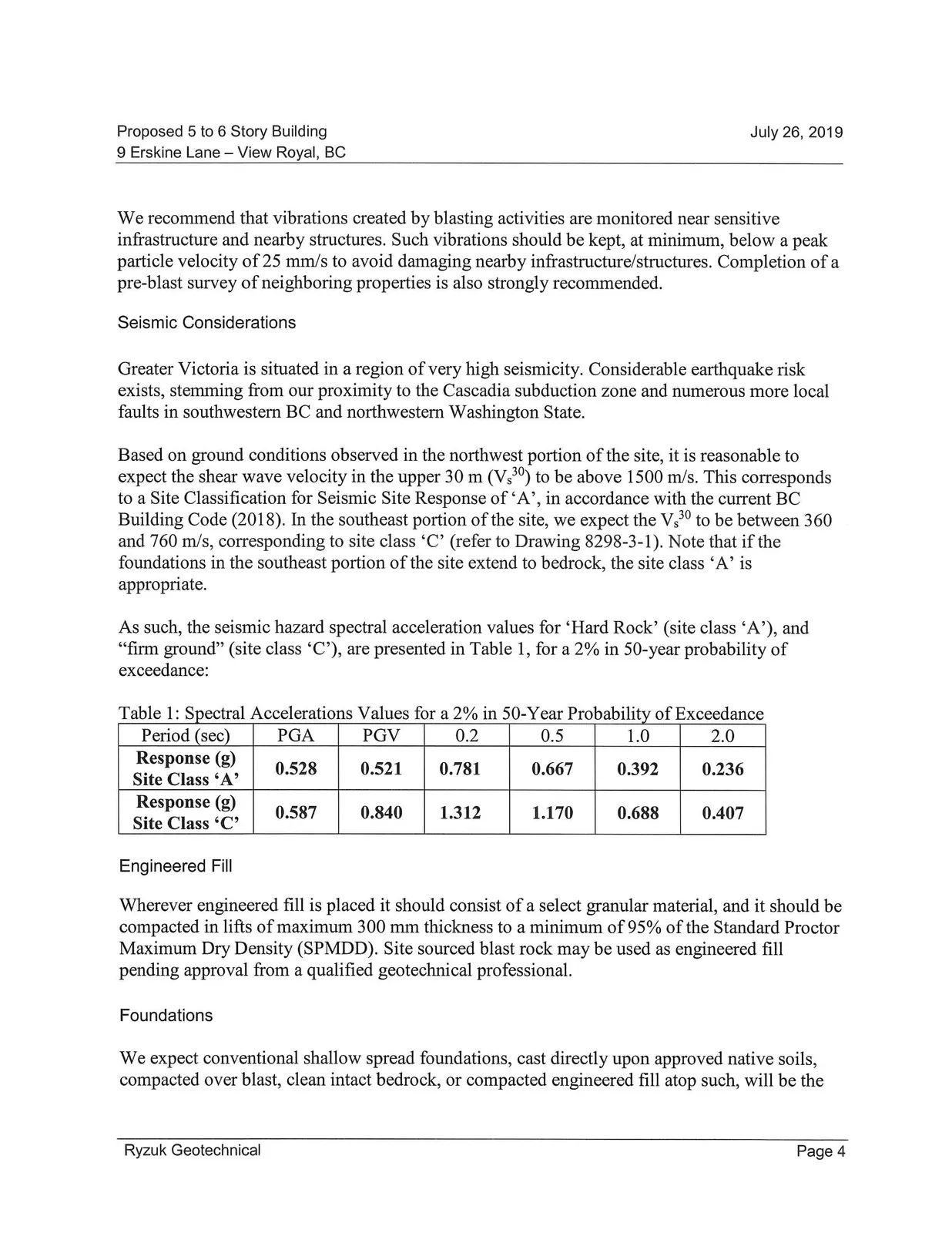
As such, the seismic hazard spectral acceleration values for ‘Hard Rock’ (site class ‘A’), and “firm ground” (site class ‘C’), are presented in Table 1, for a 2% in 50-year probability of exceedance:
Table 1: Spectral Accelerations Values for a 2% in 50-Year Probability of Exceedance
| Period (sec) | PGA | PGV | 0.2 | 0.5 | 1.0 | 2.0 |
|---|---|---|---|---|---|---|
| Response (g) Site Class 'A' | 0.528 | 0.521 | 0.781 | 0.667 | 0.392 | 0.236 |
| Response (g) Site Class 'C' | 0.587 | 0.840 | 1.312 | 1.170 | 0.688 | 0.407 |
Engineered Fill
Wherever engineered fill is placed it should consist of a select granular material, and it should be compacted in lifts of maximum 300 mm thickness to a minimum of 95% of the Standard Proctor Maximum Dry Density (SPMDD). Site sourced blast rock may be used as engineered fill pending approval from a qualified geotechnical professional.
Foundations
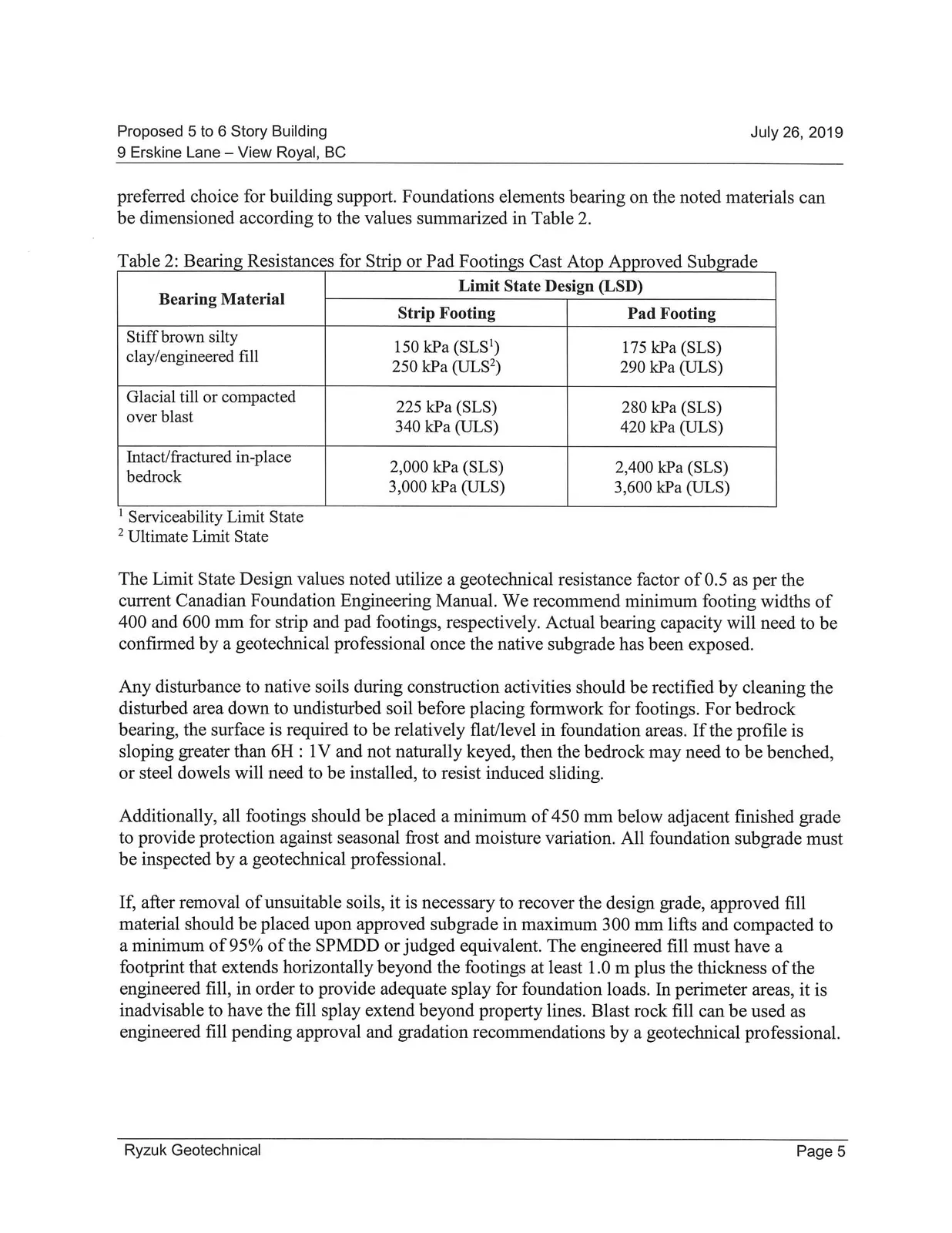
We expect conventional shallow spread foundations, cast directly upon approved native soils, compacted over blast, clean intact bedrock, or compacted engineered fill atop such, will be the preferred choice for building support. Foundations elements bearing on the noted materials can be dimensioned according to the values summarized in Table 2.
Table 2: Bearing Resistances for Strip or Pad Footings Cast Atop Approved Subgrade
| Bearing Material | Limit State Design (LSD) Strip Footing | Limit State Design (LSD) Pad Footing |
|---|---|---|
| Stiff brown silty clay/engineered fill | 150 kPa (SLS¹) 250 kPa (ULS²) |
175 kPa (SLS) 290 kPa (ULS) |
| Glacial till or compacted over blast | 225 kPa (SLS) 340 kPa (ULS) |
280 kPa (SLS) 420 kPa (ULS) |
| Intact/fractured in-place bedrock | 2,000 kPa (SLS) 3,000 kPa (ULS) |
2,400 kPa (SLS) 3,600 kPa (ULS) |
¹ Serviceability Limit State ² Ultimate Limit State
The Limit State Design values noted utilize a geotechnical resistance factor of 0.5 as per the current Canadian Foundation Engineering Manual. We recommend minimum footing widths of 400 and 600 mm for strip and pad footings, respectively. Actual bearing capacity will need to be confirmed by a geotechnical professional once the native subgrade has been exposed.
Any disturbance to native soils during construction activities should be rectified by cleaning the disturbed area down to undisturbed soil before placing formwork for footings. For bedrock bearing, the surface is required to be relatively flat/level in foundation areas. If the profile is sloping greater than 6H : 1V and not naturally keyed, then the bedrock may need to be benched, or steel dowels will need to be installed, to resist induced sliding.
Additionally, all footings should be placed a minimum of 450 mm below adjacent finished grade to provide protection against seasonal frost and moisture variation. All foundation subgrade must be inspected by a geotechnical professional.
If, after removal of unsuitable soils, it is necessary to recover the design grade, approved fill material should be placed upon approved subgrade in maximum 300 mm lifts and compacted to a minimum of 95% of the SPMDD or judged equivalent. The engineered fill must have a footprint that extends horizontally beyond the footings at least 1.0 m plus the thickness of the engineered fill, in order to provide adequate splay for foundation loads. In perimeter areas, it is inadvisable to have the fill splay extend beyond property lines. Blast rock fill can be used as engineered fill pending approval and gradation recommendations by a geotechnical professional.
Settlement Considerations
Provided all loose and deleterious material is removed from all building/foundation and road/parking areas, we expect that settlement at this site will be well within structural tolerances, given the anticipated soil conditions.
Foundation Walls
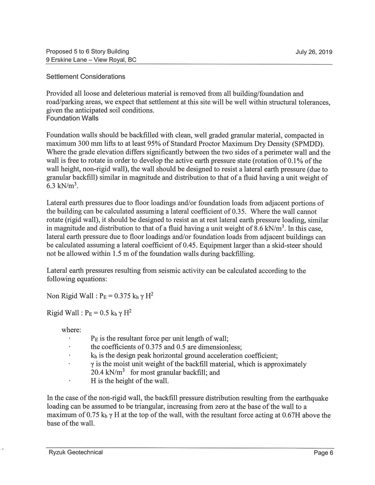
Foundation walls should be backfilled with clean, well graded granular material, compacted in maximum 300 mm lifts to at least 95% of Standard Proctor Maximum Dry Density (SPMDD). Where the grade elevation differs significantly between the two sides of a perimeter wall and the wall is free to rotate in order to develop the active earth pressure state (rotation of 0.1% of the wall height, non-rigid wall), the wall should be designed to resist a lateral earth pressure (due to granular backfill) similar in magnitude and distribution to that of a fluid having a unit weight of 6.3 kN/m³.
Lateral earth pressures due to floor loadings and/or foundation loads from adjacent portions of the building can be calculated assuming a lateral coefficient of 0.35. Where the wall cannot rotate (rigid wall), it should be designed to resist an at rest lateral earth pressure loading, similar in magnitude and distribution to that of a fluid having a unit weight of 8.6 kN/m³. In this case, lateral earth pressure due to floor loadings and/or foundation loads from adjacent buildings can be calculated assuming a lateral coefficient of 0.45. Equipment larger than a skid-steer should not be allowed within 1.5 m of the foundation walls during backfilling.
Lateral earth pressures resulting from seismic activity can be calculated according to the following equations:
Non Rigid Wall : $P_E = 0.375\ k_h\ \gamma\ H^2$
Rigid Wall : $P_E = 0.5\ k_h\ \gamma\ H^2$
where:
- $P_E$ is the resultant force per unit length of wall;
- the coefficients of 0.375 and 0.5 are dimensionless;
- $k_h$ is the design peak horizontal ground acceleration coefficient;
- $\gamma$ is the moist unit weight of the backfill material, which is approximately 20.4 kN/m³ for most granular backfill; and
- $H$ is the height of the wall.
In the case of the non-rigid wall, the backfill pressure distribution resulting from the earthquake loading can be assumed to be triangular, increasing from zero at the base of the wall to a maximum of $0.75\ k_h\ \gamma\ H$ at the top of the wall, with the resultant force acting at $0.67H$ above the base of the wall.
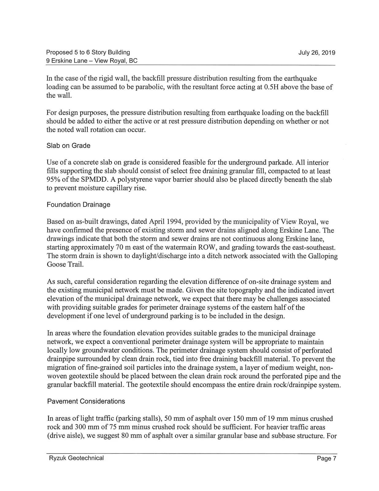
In the case of the rigid wall, the backfill pressure distribution resulting from the earthquake loading can be assumed to be parabolic, with the resultant force acting at $0.5H$ above the base of the wall.
For design purposes, the pressure distribution resulting from earthquake loading on the backfill should be added to either the active or at rest pressure distribution depending on whether or not the noted wall rotation can occur.
Slab on Grade
Use of a concrete slab on grade is considered feasible for the underground parkade. All interior fills supporting the slab should consist of select free draining granular fill, compacted to at least 95% of the SPMDD. A polystyrene vapor barrier should also be placed directly beneath the slab to prevent moisture capillary rise.
Foundation Drainage
Based on as-built drawings, dated April 1994, provided by the municipality of View Royal, we have confirmed the presence of existing storm and sewer drains aligned along Erskine Lane. The drawings indicate that both the storm and sewer drains are not continuous along Erskine lane, starting approximately 70 m east of the watermain ROW, and grading towards the east-southeast. The storm drain is shown to daylight/discharge into a ditch network associated with the Galloping Goose Trail.
As such, careful consideration regarding the elevation difference of on-site drainage system and the existing municipal network must be made. Given the site topography and the indicated invert elevation of the municipal drainage network, we expect that there may be challenges associated with providing suitable grades for perimeter drainage systems of the eastern half of the development if one level of underground parking is to be included in the design.
In areas where the foundation elevation provides suitable grades to the municipal drainage network, we expect a conventional perimeter drainage system will be appropriate to maintain locally low groundwater conditions. The perimeter drainage system should consist of perforated drainpipe surrounded by clean drain rock, tied into free draining backfill material. To prevent the migration of fine-grained soil particles into the drainage system, a layer of medium weight, non-woven geotextile should be placed between the clean drain rock around the perforated pipe and the granular backfill material. The geotextile should encompass the entire drain rock/drainpipe system.
Pavement Considerations
In areas of light traffic (parking stalls), 50 mm of asphalt over 150 mm of 19 mm minus crushed rock and 300 mm of 75 mm minus crushed rock should be sufficient. For heavier traffic areas (drive aisle), we suggest 80 mm of asphalt over a similar granular base and subbase structure. For asphalt selection, Master Municipal Construction Document (MMCD) UC#2 would be sufficient. In areas of frequent heavy traffic (i.e. adjacent to garbage bins) concrete pads are appropriate. Granular base and subbase fills should be compacted to at least 95% of SPMDD.
Closure
We trust the preceding is suitable for your purposes at present. Please don’t hesitate to contact our office if we can be of further assistance.
Yours truly, Ryzuk Geotechnical
Attachments: Terms of Engagement Site Location Plan (Drawing 8298-3-1)
Document Images
(8)