Environmental Development Permit No. 2017/07 - 2215 Meadowvale Drive
Staff report regarding an environmental development permit to allow for native planting and deck siting at 2215 Meadowvale Drive.
View Royal Casino Expansion
1708 Old Island Highway, View Royal, B.C.
Issued for Development Permit Amendment Resubmission
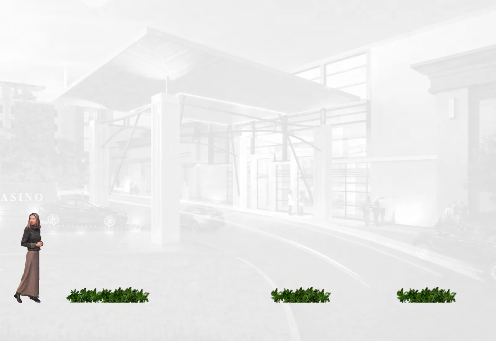
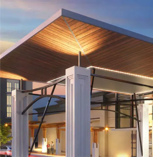

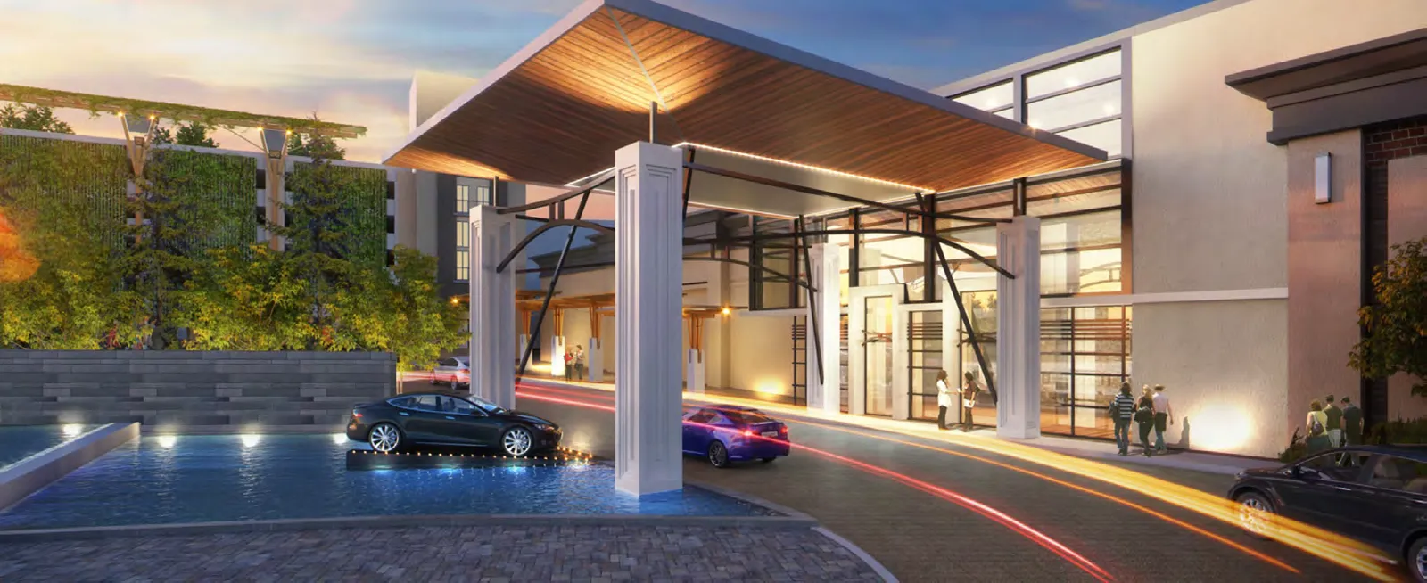
Consultant: Chris Dikeakos Architects Inc. Client: Great Canadian Gaming Corporation Date: August 26, 2016
Enlarged Site Plan (South) Water Feature
Drawing No: A101 Revision Date: August 30, 2017
Site Legend
| Symbol | Description |
|---|---|
| LS | Lamp Standard |
| BP | Bike Parking |
| L | Loading Zone |
| GAS | Gas Meters |
| DR | Drain |
| CB | Catch Basin |
| LB | Lawn Basin |
| CL | Centerline |
| T.O.C | Top of Concrete |
| TD | Top of Drain |
| TW | Top of Wall |
| B.S | Bottom of Stair |
| FDC | Fire Department Connection |
| FH | Fire Hydrant |
| B | Bollard |
| MH | Man Hole |
| NP | "No Parking Fire Truck Access Route" Signage |
| NS | "No Stopping" Signage |
| AP | "Permit Required Accessible Parking" Signage |
| CW | Cross Walk Signage (Double Sided) |
| SS | Stop Sign |
| 00.0 | Elevation |
| [S] | Sidewalk Letdown |
Site Plan General Notes
Coordinate with Struct. Engineer, Civil Engineer and Landscape Architect:
- Paving details, material & patterns
- Curbs & letdown details
- Bollards
- Lamp standard bases
- Site grading and catch basin locations
- Site planting and grades
- Parking lot line painting
Level 1 Floor Plan
Drawing No: A202 Date: February 10, 2017
Legend
| Symbol | Description |
|---|---|
| DN | Down |
| UP | Up |
| TYP. | Typical |
| ELEC. | Electrical |
| CENTERLINE | Centerline |
| MECH. | Mechanical |
| AP | Access Panel |
| SQ.M. | Square Meter |
| EP | Electrical Panel |
| FE | Fire Extinguisher Cabinet |
| min. | Minute |
| hr. | Hour |
| DR | Drain |
| DR2 | Two-Tier Drain |
| UNO | Unless Noted Otherwise |
| CB | Catch Basin |
| X | Panic Button |
| AKP | Alarm Keypad |
| HS | Hand Scanner |
| MKP | Mechanical Keypad |
| INT | Intercom |
| D | Detex Push Bar |
| RH | Rope Hook |
| MS | Motion Sensor |
| KP | Key Pad |
| MIN. | Minimum |
Sign Location Master Site Plan
Scale: 1/64"=1'-0"

Sign Legend
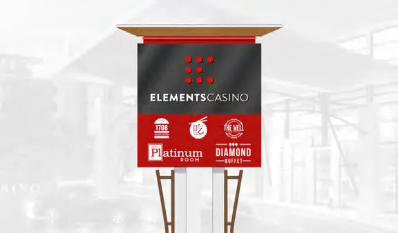
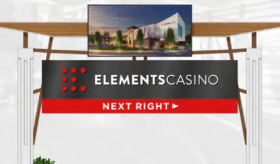
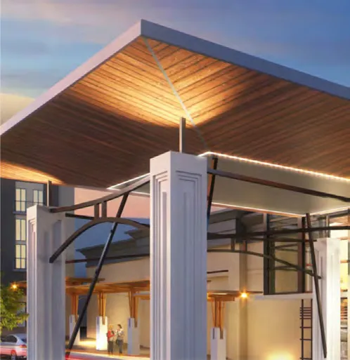
- N1: New freestanding pylon sign to match building porte cochere
- N2: New dual pole pylon structure with illuminated push through logo and 12mm electronic message centre
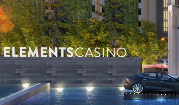
- N3: New dimensional ELEMENTS monument sign at water feature
- N4: New illuminated channel letter ELEMENTS logo on building fascia
- N5: New rectangular sign cabinet with illuminated push through logo
- N6: New rectangular sign cabinet with illuminated push through logo
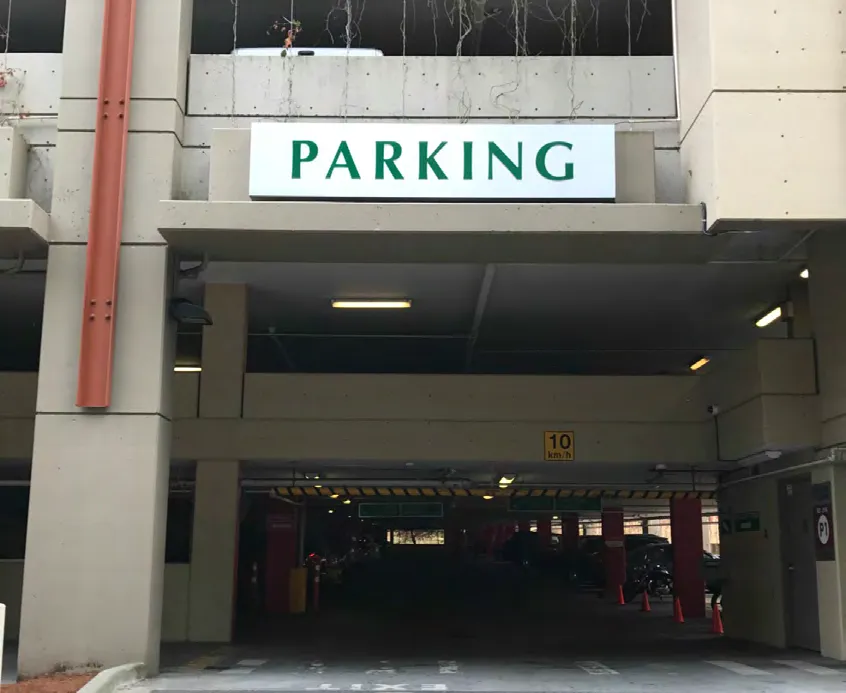
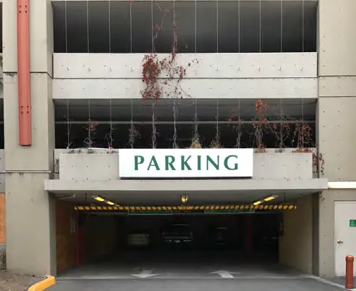
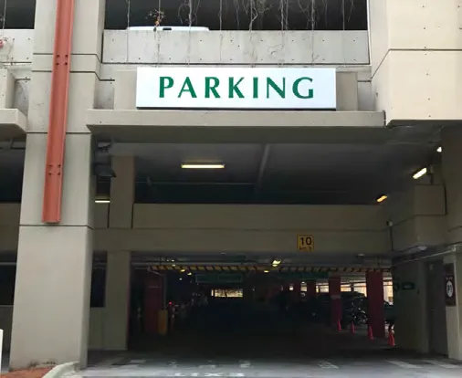
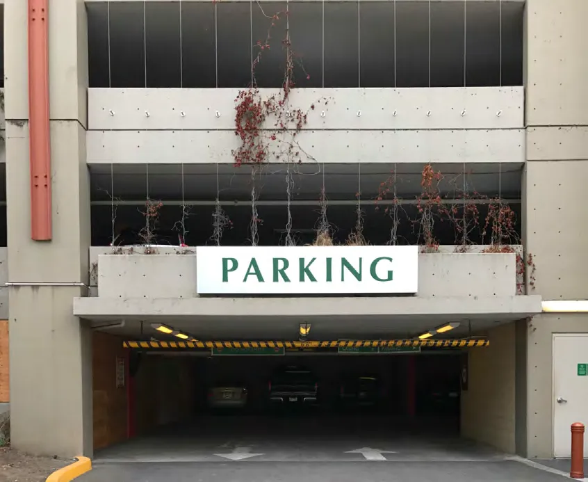
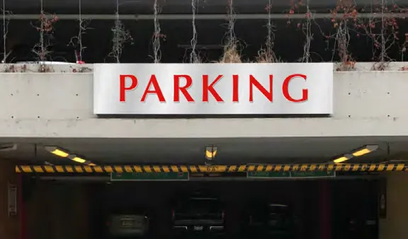
- E1: Replace vinyl graphic on existing north parkade entrance sign
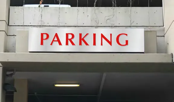
- E2: Replace vinyl graphic on existing east parkade entrance sign
Sign N1: New Freestanding Pylon Sign
Description: New freestanding pylon sign with illuminated push through logo to match porte cochere roof structure.

Pylon Specifications
- A: Fabricated aluminum roof structure painted satin white with 1 X 4 wood plank soffit to match building porte cochere
- B: Recessed aluminum channel painted satin red with GE Tetra (or equivalent rigid LED light effect (red)
- C: Double sided aluminum upper sign cabinet painted satin black with illuminated 1/2" push through acrylic ELEMENTS logo. Translucent red and white faces with rear diffusion film
- D: Double sided aluminum lower sign cabinet painted satin red with illuminated rout-to-void logos and translucent white acrylic backer (Match red vinyl inner graphic fills to cabinet paint)
- E: 2 X 2" square tube vertical trim painted satin brown to match building porte cochere and N2 dual pole pylon metal work
- F: Dual 8 X 8 X 1/4" HSS support poles painted satin white with 12 X 20" steel connector plates and triangulated gussets. (no cladding required)
- G: Pad or pile type reinforced concrete base with internal re-bar support cage and 1 1/2" J bolt connectors (X4)
Sign N2: New Rectangular Sign Cabinet
Description: New rectangular sign cabinet with illuminated push through logo, RGB electronic message centre on pre-existing dual pole structure.
Pylon Specifications
- A: Monocoque style plate steel pylon cross beam with 1" recessed faces and 1 X 4 wood plank trim to match building porte cochere (by others)
- B: 3 x 3" HSS sign cabinet support frame spanning between vertical end columns (by others)
- C: 14 X 14" sculpted concrete column with internal 4 X 4" HSS vertical support poles (by others)
- D: 96 X 200 matrix 12mm RGB electronic message centre with wireless remote control. (approx 4' X 8')
- E: 6" deep single sided aluminum upper sign cabinet painted satin black with illuminated 1/2" push through acrylic ELEMENTS logo. Translucent red and white faces with rear diffusion film
- F: 6" deep single sided aluminum lower sign cabinet painted satin red with illuminated rout-to-void wayfinding copy and translucent white acrylic backer
- G: Pad or pile type reinforced concrete base with internal re-bar support cage (by others)
Sign N3: New 1" Aluminum Letters
Description: New 1" aluminum letters pin mounted on arched basalt water feature.

Letter Specifications
- A: 1" thick aluminum letters painted semi gloss white
- B: 1" X 1" roll formed square tube aluminum mounting rail with welded end caps on 121'-0" radius arc
- C: Basalt water feature with solid concrete top cap by others
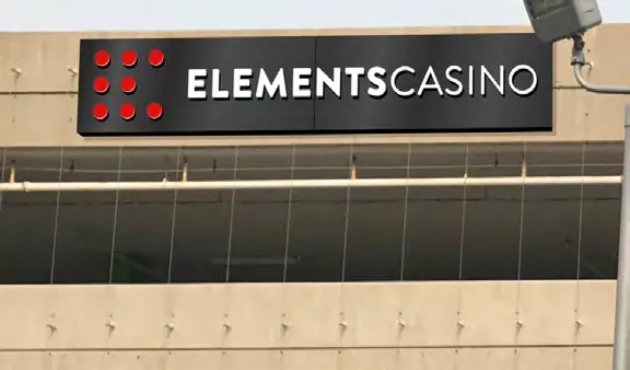
Sign N4: New Illuminated Channel Letter Fascia Sign
Description: New illuminated channel letter fascia sign with day/night letter copy and through wall wiring (horizontal logo).
Channel Letter Specifications
- A: Illuminated logo discs with translucent white acrylic faces and red vinyl laminate. 5" deep Letteredge returns painted red to match
- B: Illuminated channel letters with translucent white acrylic faces and perforated black vinyl laminate. 5" deep Letteredge returns painted satin black
- C: 1/2" threaded "pass thru" conduit for low voltage power feed to individual channel letters
- D: Low voltage power supplies in metal wiring raceway behind exterior fascia wall. 120v 6a input power feed
Sign N5: New Rectangular Sign Cabinet
Description: New rectangular sign cabinet with illuminated push through logo on south fascia screen structure.
Fascia Sign Specifications
- A: 6" deep aluminum sign cabinet painted satin black with illuminated 1/2" push through acrylic ELEMENTS logo. Translucent red and white faces with rear diffusion film
- B: 2" X 2" square tube aluminum bracket (X2) with flat bar mounting tabs into sides of vertical panel supports. Ensure adequate clearance between bracket and undulating panels
- C: 3/4" X 6" aluminum flat bar vertical panel frame by others on 8'-1 1/4" centers. (Confirm spacing before production)
- D: Perforated undulating aluminum panel system by others. (Each row reversed projection)
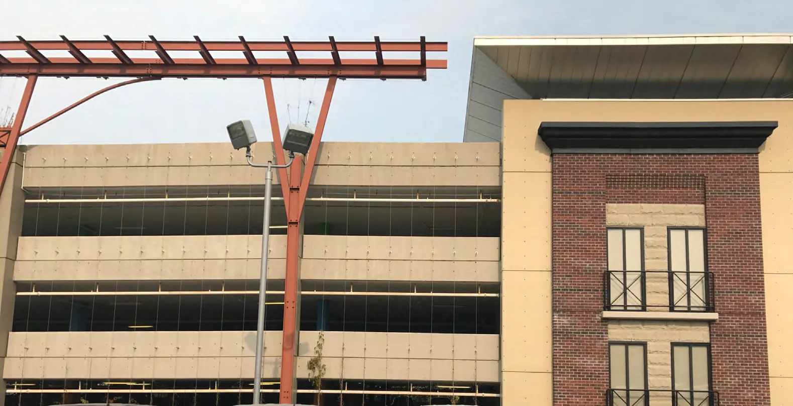
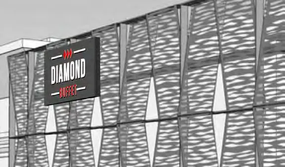
Sign N6: New Rectangular Sign Cabinet
Description: New rectangular sign cabinet with illuminated push through logo on west parkade fascia.
Fascia Sign Specifications
- A: 6" deep aluminum sign cabinet painted satin black with illuminated 1/2" push through acrylic ELEMENTS logo. Translucent red and white faces with rear diffusion film
- B: 4" X 30" high vertical blade spacer brackets fastened to concrete fascia (X4 pcs) Ensure adequate clearance for existing tensioned cable stays
- C: Maximum useable fascia height: 51"
Sign E1-2: Parkade Entrance Fascia Signs
Description: Replace translucent vinyl faces on existing illuminated push through parkade entrance signs.

Fascia Sign Specifications
- A: Replace existing translucent green vinyl letter faces with new translucent red vinyl
- B: Existing metallic silver sign cabinet with illuminated push through acrylic letter copy