Architectural and Landscape Concept Plans - RENTAL APARTMENTS 346 ISLAND HIGHWAY
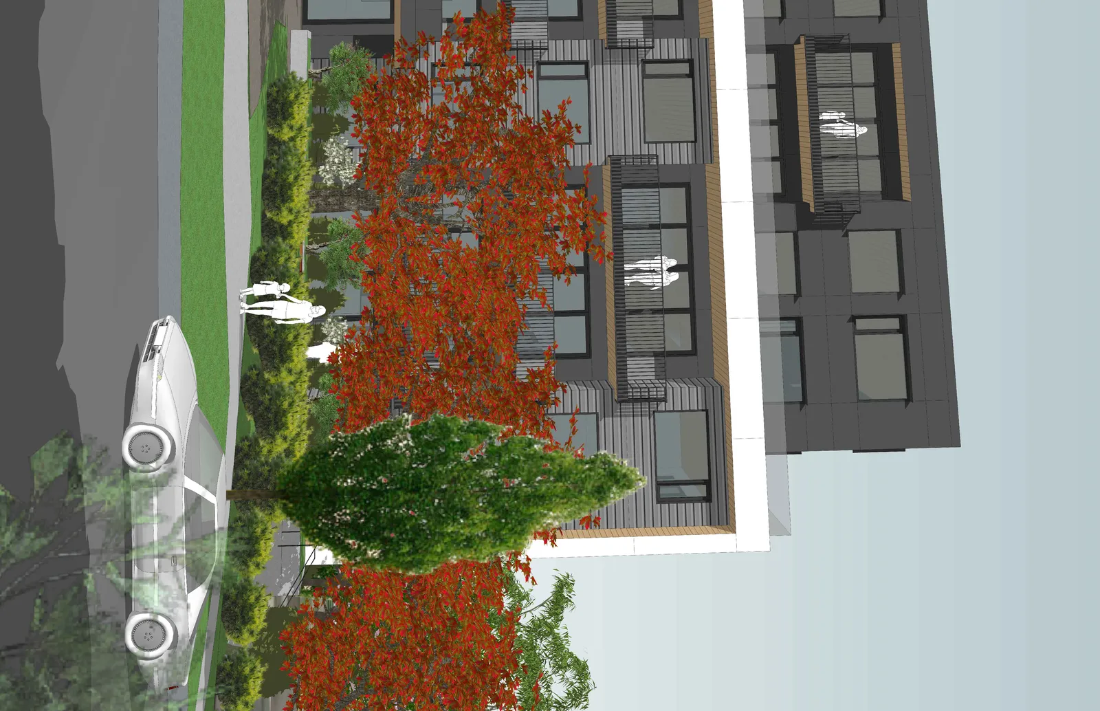
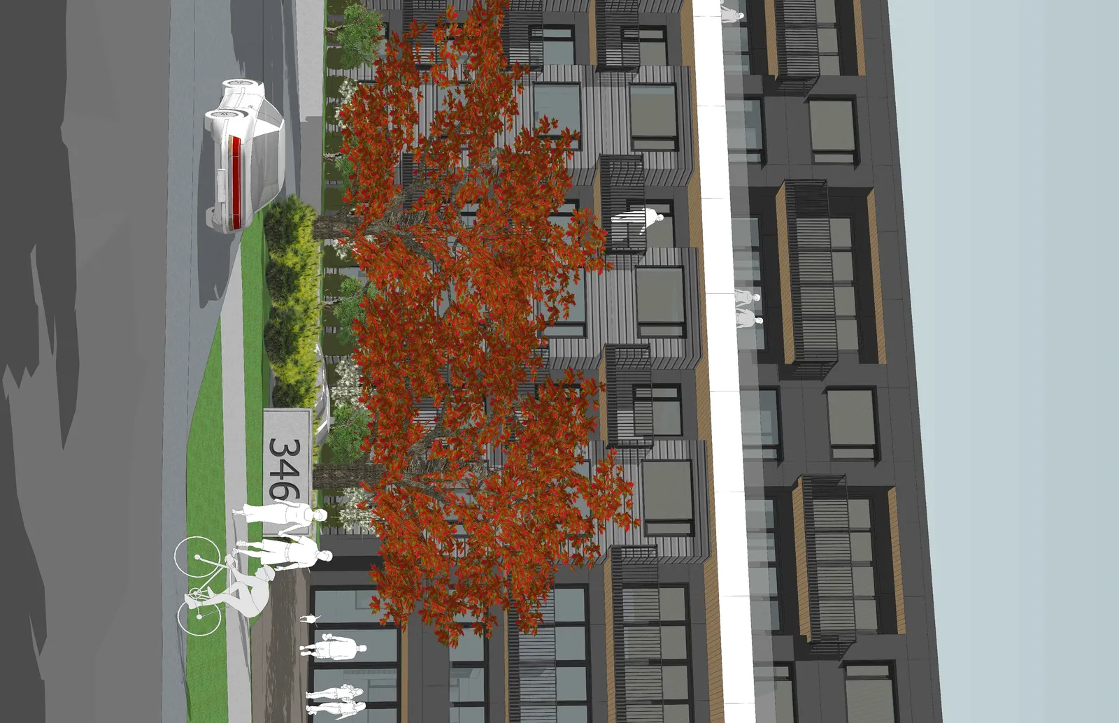
A set of detailed architectural drawings including site plans, project data, site sections, shadow studies, and building renderings.
RENTAL APARTMENTS
Civic Address: 346 ISLAND HIGHWAY, VIEW ROYAL, BC
Legal Addresses:
- PT LOT 1, PLAN 5384 EXCEPT WESTERLY 40' P.I.D. 005-967-619
- WESTERLY 40' PT LOT 1, PLAN 5384 P.I.D. 005-967-660 Project Description: 94 UNIT, 6 STOREY MULTI FAMILY RESIDENTIAL BUILDING OCP Designation: IMU - INTENSIVE MIXED-USE FORM AND CHARACTER Site Area: 3573.7 SM Zoning:
- Proposed: CD
- Existing: R-2 Floor Area: 7,358.5 SM (Refer to sheet A040 for floor area calculations)
Unit Breakdown
| UNIT TYPE | QUANTITY | % |
|---|---|---|
| TYPE A1 - STUDIO | 12 | 12.8 |
| TYPE A2 - STUDIO | 2 | 2.1 |
| TYPE A3 - JR. 1 BED | 8 | 8.5 |
| TYPE B1 - 1 BED | 3 | 3.2 |
| TYPE B2 - 1 BED | 28 | 29.8 |
| TYPE B3 - 1 BED | 2 | 2.1 |
| TYPE B4 - 1 BED | 4 | 4.3 |
| TYPE C1 - 1 BED + DEN | 4 | 4.3 |
| TYPE C2 - 1 BED + DEN | 4 | 4.3 |
| TYPE C3 - 1 BED + DEN | 2 | 2.1 |
| TYPE D1 - 2 BED | 1 | 1.1 |
| TYPE D2 - 2 BED | 3 | 3.2 |
| TYPE D3 - 2 BED | 3 | 3.2 |
| TYPE D4 - 2 BED | 2 | 2.1 |
| TYPE E1 - 2 BED + DEN | 4 | 4.3 |
| TYPE E2 - 2 BED + DEN | 4 | 4.3 |
| TYPE F1 - 3 BED | 4 | 4.3 |
| TYPE F2 - 3 BED | 2 | 2.1 |
| TYPE F3 - 3 BED | 2 | 2.1 |
| TOTAL | 94 | 100% |
- Site Coverage: Proposed 35%, Permitted (RM-3) 60% (1250.2 SM / 3,573.7 SM)
- Floor Space Ratio (FSR): 2.06 FSR (7,358.5 SM / 3,573.7 SM)
- Height of Building: Proposed 22.15M, Permitted 13.5 M
Setbacks + Projections
| SETBACK | PROPOSED (M) |
|---|---|
| FRONT LOT LINE | 7.5 |
| WEST SIDE LOT LINE | 7.5 |
| WEST SIDE LOT LINE @ L5-L6 | 13.9 |
| EAST SIDE LOT LINE | 4.0 |
| EAST SIDE LOT LINE @ L5-L6 | 5.9 |
| REAR LOT LINE | 3.0 |
Parking Calculations
Total Parking Required: 111
- 69: 1 BED UNITS X 1 SPACES/UNIT
- 26: 17 - 2 BED UNITS X 1.5 SPACES/UNIT
- 16: 8 - 3 BEDROOM UNITS X 2 SPACES/UNIT
| TYPE | PROPOSED |
|---|---|
| RESIDENTIAL (REGULAR) | 70 |
| RESIDENTIAL (ACCESSIBLE) | 1 |
| RESIDENTIAL (SMALL) | 13 |
| TOTAL | 84 |
| VISITOR (REGULAR) | 7 |
| VISITOR (SMALL) | 1 |
| VISITOR (SURFACE) | 2 |
| TOTAL | 10 |
| DROP OFF SPACES | 1 |
| TOTAL | 95 |
| SMALL CAR % | 15% (14/92) 30% MAX |
Bicycle Storage Summary
| TYPE | PROPOSED | REQUIRED |
|---|---|---|
| CLASS I BICYCLE SPACES | 126 | 94 (1 PER UNIT) |
| CLASS II BICYCLE SPACES | 10 | 06 |
Storage Summary
| TYPE | PROPOSED |
|---|---|
| 3' x 4' LOCKER | 96 |
Building Code Information
- Applicable Building Code: BCBC 2018
- Major Occupancy Classification: 3.2.2.50 GROUP C, UP TO 6 STOREYS
- Number of Storeys: 6
- Sprinklered: YES
- NFPA Standard: 13
- Facing: 1 STREET
- Maximum Area: 1500 m²
- Maximum Height: 18 m
- Construction Type: COMBUSTIBLE
- Floor Assemblies: 1 HR
- Wall Assemblies: -
- Roof Assemblies: 1 HR
Project Team
- Owner's Rep / Contractor: GT MANN CONTRACTING LTD. 1551 BROADMEAD AVE, VICTORIA BC V8P 2V1, 250-857-5349, CONTACT: GRAEME MANN, GRAEME@GTMANN.COM
- Architect: URBAN WEST ARCHITECTURE INC. 102-1688 WEST 1ST AVE. VANCOUVER, BC V6J 1G1, 604-603-1332, CONTACT: JUSTIN BENNETT, JUSTIN@UWARCHITECTURE.COM
- Landscape: LOMBARD NORTH GROUP INC. 836 CORMORANT STREET, VICTORIA, B.C. V8W 1R1, 250-386-3336, CONTACT: JAMES PARTLOW, LOMBARDNORTHGROUP@GMAIL.COM
- Civil: MCELHANNEY 500-3960 QUADRA STREET, VICTORIA, BC V8X 4A3, 778 746 7417, CONTACT: NATHAN DUNLOP, NDUNLOP@MCELHANNEY.COM
- Arborist: TALBOT MCKENZIE AND ASSOCIATES, BOX 48153 RPO UPTOWN, VICTORIA BC V8Z 7H6, 250-479-8733, CONTACT: ROBERT MCRAE, ROBBIE@TALMACK.CA
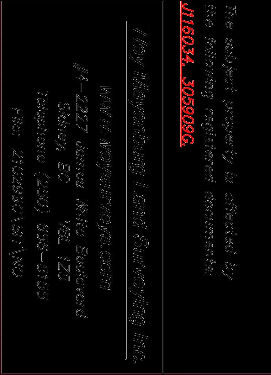
- Surveyor: WEY MAYENBURG LAND SURVEYING INC, 4-2227 JAMES WHITE BOULEVARD, SIDNEY, BC V8L 1Z5, 250-656-5155, CONTACT: BRENT MAYENBURG, BRENT@WEYSURVEYS.COM
- Traffic: WATT CONSULTING GROUP, 302-740 HILLSIDE AVE, VICTORIA BC, V8T 1Z4, 250-388-9877, CONTACT: TIM SHAH, TSHAH@WATTCONSULTINGGROUP.COM
Drawing List
| NO. | NAME |
|---|---|
| ARCHITECTURAL | |
| A000 | PROJECT INFO, AERIAL CONTEXT PLAN & PROJECT MASSING |
| A010 | SITE SURVEY |
| A011 | CONTEXT PLAN |
| A012 | SITE PLAN |
| A015 | SITE SECTIONS |
| A020 | SHADOW STUDY |
| A021 | MATERIAL PALETTE |
| A030 | PROJECT VIEWS |
| A031 | PROJECT VIEWS |
| A032 | PROJECT VIEWS |
| A040 | FLOOR AREA CALCULATIONS |
| A200 | LEVEL P2 PLAN |
| A201 | LEVEL P1 PLAN |
| A202 | LEVEL 1 PLAN |
| A203 | LEVEL 2-4 PLANS |
| A204 | LEVEL 5 PLAN |
| A205 | LEVEL 6 PLAN |
| A206 | ROOF PLAN |
| A250 | ENLARGED SUITE PLANS |
| A251 | ENLARGED SUITE PLANS |
| A252 | ENLARGED SUITE PLANS |
| A253 | ENLARGED SUITE PLANS |
| A254 | ENLARGED SUITE PLANS |
| A300 | ELEVATIONS - SOUTH AND EAST |
| A301 | ELEVATIONS - NORTH AND WEST |
| A400 | BUILDING SECTIONS |
| A401 | BUILDING SECTIONS |
| A402 | BUILDING SECTIONS |
| A403 | BUILDING SECTIONS |
| LANDSCAPE | |
| L1 | PRELIMINARY SITE PLAN |
General Notes
- Written dimensions take precedence. Do not scale drawings. Details shall govern over plans & elevations.
- All drawings shall be read in conjunction with drawings & specification prepared by consultants including: structural, mechanical, electrical, plumbing, civil & landscape drawings, geotechnical, acoustic, and code reports. Any discrepancies must be reported to architect before proceeding with work.
- Verify all grades, lines, datum & dimensions and report any inconsistencies to the architect. Where a discrepancy exists between the design documents and the site conditions, the contractor shall be responsible for notifying the consultant team & architect in sufficient time to allow for resolution of the problem without effect upon the construction schedule. Failure to report inconsistencies shall not relieve the contractor from the responsibility of correcting same. Establish lines, grades, elevations, etc. for all trades involved in the construction.
- Verify all figure dimensions shown on contract documents. Prior to constructing elements, review documents for conflicting dimensions and notify the consultant who will issue clarifications or additional dimensions as required. The contractor shall be required to rectify any errors resulting from his failure to verify dimensions before proceeding.
- Exterior dimensions shall be to face of concrete and/or outside face of wall sheathing u.n.o., interior dimensions shall be to face of stud u.n.o.
- All dimensions, notes & details shown on one portion of a drawing shall apply typically to all opposite and/or mirrored conditions u.n.o.
- Verify all equipment sizes before beginning work.
- General notes on one design document are applicable on all documents.
- All buildings, construction materials & procedures shall conform to the 2019 edition of the Vancouver Building Code, current mechanical, plumbing & fire codes, national electrical code and any other local governing codes and ordinances. In the event of conflicts in code requirements, the most stringent requirements shall apply. Refer also to code compliance report prepared by code consultant.
- Shop drawings for prefabricated elements shall be submitted for architect's review prior to fabrication. A list of required submittals will be provided at site start up meeting. General contractor shall review shop drawings prior to submitting to architect. No work shall be fabricated prior to review of shop drawings by architect/ consultants. Samples, catalogue cuts, colour charts or other materials shall be submitted as applicable or as instructed by the consultant, for review & selection. Install reviewed and approved items only.
- All work subject to periodic field review by architect and/or other registered professional & consulting engineers named on this document, to meet the authority having jurisdiction's letters of assurance / compliance requirements. List of required inspection will be provided at site startup meeting.
- All work started on the project by any sub-contractor shall mean that the above requirements have been reviewed and that no extra claim for cost shall be put forward to meet the professional consultant's field review requirements.
- The general contractor shall keep record of and retain all copies of the authority having jurisdiction's inspection reports, and provide copies to the architect for their records.
- Where required or as otherwise requested provide all blocking, fiirestopping & fireproofing.
- Ventilate enclosed spaces to the standards required by the BC Building Code.
- The contractor shall be responsible for adequately framing, bracing & structuring all walls, bulkheads and other drywall construction in accordance with applicable typical details contained in the drawings, whether or not specifically referenced in the plans.
- Coordinate location & provide blocking, backing and/or reinforcements in partitions for all cabinets, countertops and any wall-mounted items. Refer to elevations & details for location of wall standards and other supports. Provide all additional drywall framing, bracing, hangers, lintel supports etc. as required, in addition to that indicated upon the design documents.
- Run all hot and cold water lines & piping inside interior walls only and insulate around. Insulate all sanitary & storm lines within walls where required, refer to mechanical drawings.
- Extent of waterproofing vs damproofing of foundation walls and all core walls below grade to be reviewed on site by architect, envelope consultant, geotech engineer & warranty provider. Conditions can not be determined until further investigation is done @ time of excavations.
- ACQ. Lumber / Connections. Fasteners in contact with ACQ. Lumber shall be stainless steel. Hangers / brackets / saddles in contact with ACQ. Lumber shall be stainless steel or hot dipped galvanized with isolation membrane.
Page 2: Site Survey
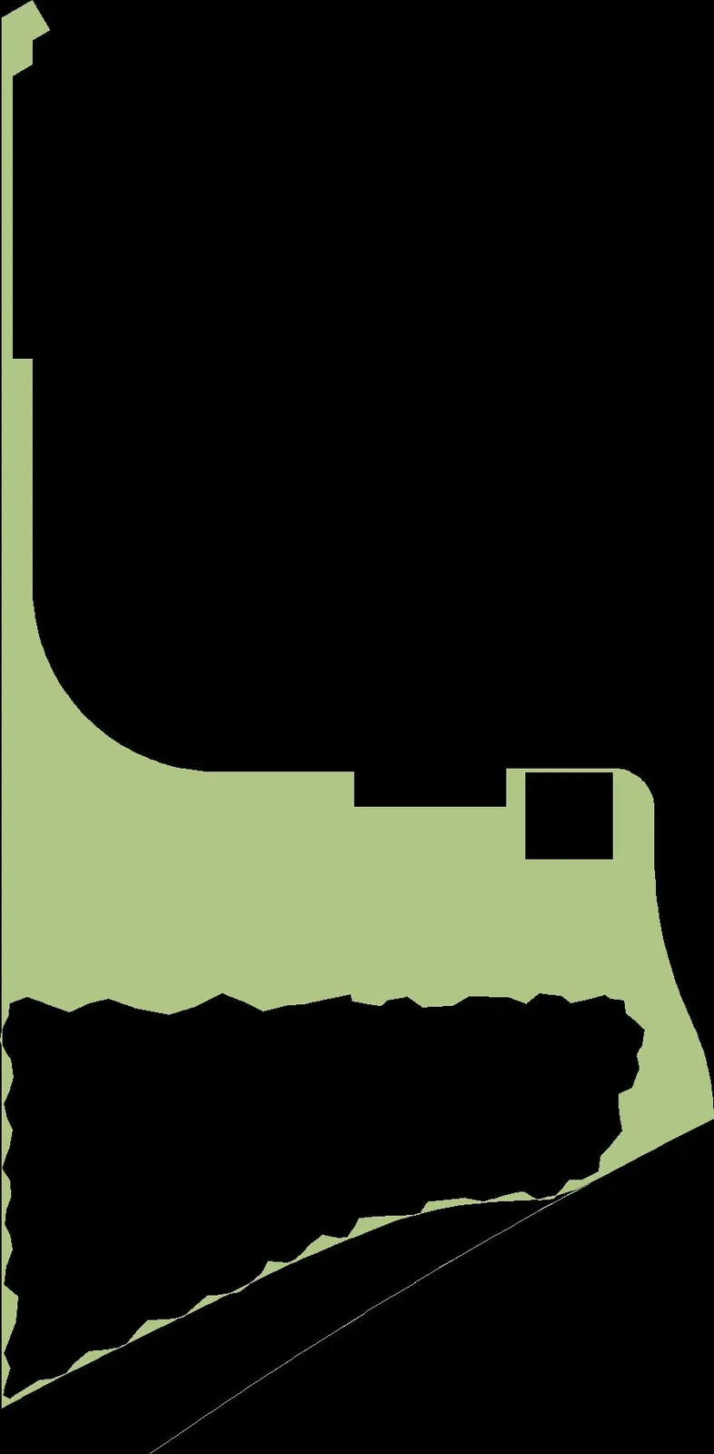
Topographic Site Plan Of: That Part of Lot 1, Section 92, Esquimalt District, Plan 5384, Lying To The South Of The Right Of Way Of The Esquimalt And Nanaimo Railway As Shown On Said Plan, Except Thereout All That Part Lying To The West Of A Boundary Parallel To And Perpendicularly Distant 40 Feet From The Westerly Boundary Of Said Plan And That Part of Lot 1, Section 92, Esquimalt District, Plan 5384, Lying To The South Of The Right Of Way Of The Esquimalt And Nanaimo Railway Company As Said Right Of Way Is Shown On Said Plan, And To The West Of A Boundary Parallel To And Perpendicularly Distant 40 Feet From The Westerly Boundary Of Said Lot. P.I.D. 005-967-619 & 005-967-660.
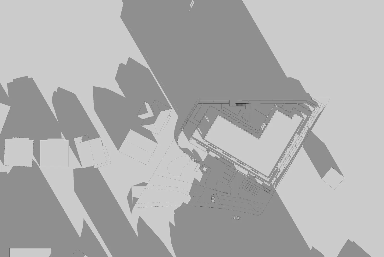
Page 3: Context Plan
Page 4: Site Plan
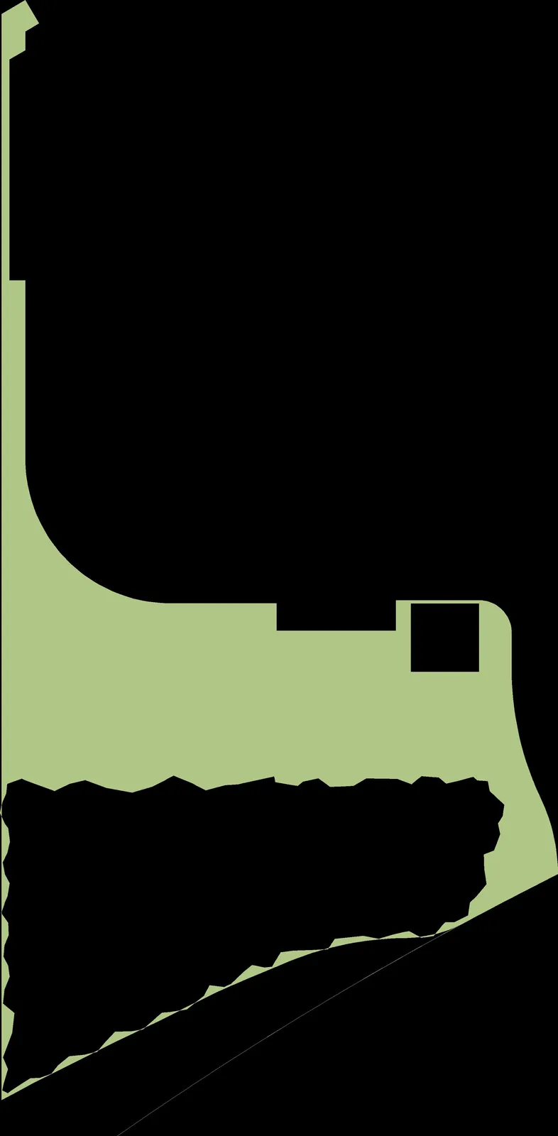
A012 SITE PLAN
[Image 4-15: Map snippets showing the building footprint, site access, landscaping, and setbacks.]
Grade Calculation
- POINT 1: F.G. 18.40m, E.G. 15.77m
- POINT 2: F.G. 18.40m, E.G. 13.35m
- POINT 3: F.G. 18.40m, E.G. 14.25m
- POINT 4: F.G. 18.40m, E.G. 14.93m
- POINT 5: F.G. 18.40m, E.G. 15.51m
- POINT 6: F.G. 18.40m, E.G. 16.37m
Calculations:
- POINTS 1-2: (15.77m+13.35m)/2 x 42.92m = 624.92m²
- POINTS 2-3: (13.35m+14.25m)/2 x 20.02m = 276.28m²
- POINTS 3-4: (14.25m+14.93m)/2 x 18.66m = 272.25m²
- POINTS 4-5: (14.93m+15.51m)/2 x 30.75m = 468.02m²
- POINTS 5-6: (15.51m+16.37m)/2 x 20.86m = 332.51m²
- POINTS 6-1: (16.37m+15.77m)/2 x 50.28m = 808.00m²
Average Grade Calculation: (624.92m² + 276.28m² + 272.25m² + 468.02m² + 332.51m² + 808.00m²) / (42.92m + 20.02m + 18.66m + 30.75m + 20.86m + 50.28m) = 2781.96m² / 183.49m = 15.16m
Page 5: Site Sections
A015 SITE SECTIONS
- SITE SECTION - 1:300
- SITE SECTION - 1:300
Page 6: Shadow Study
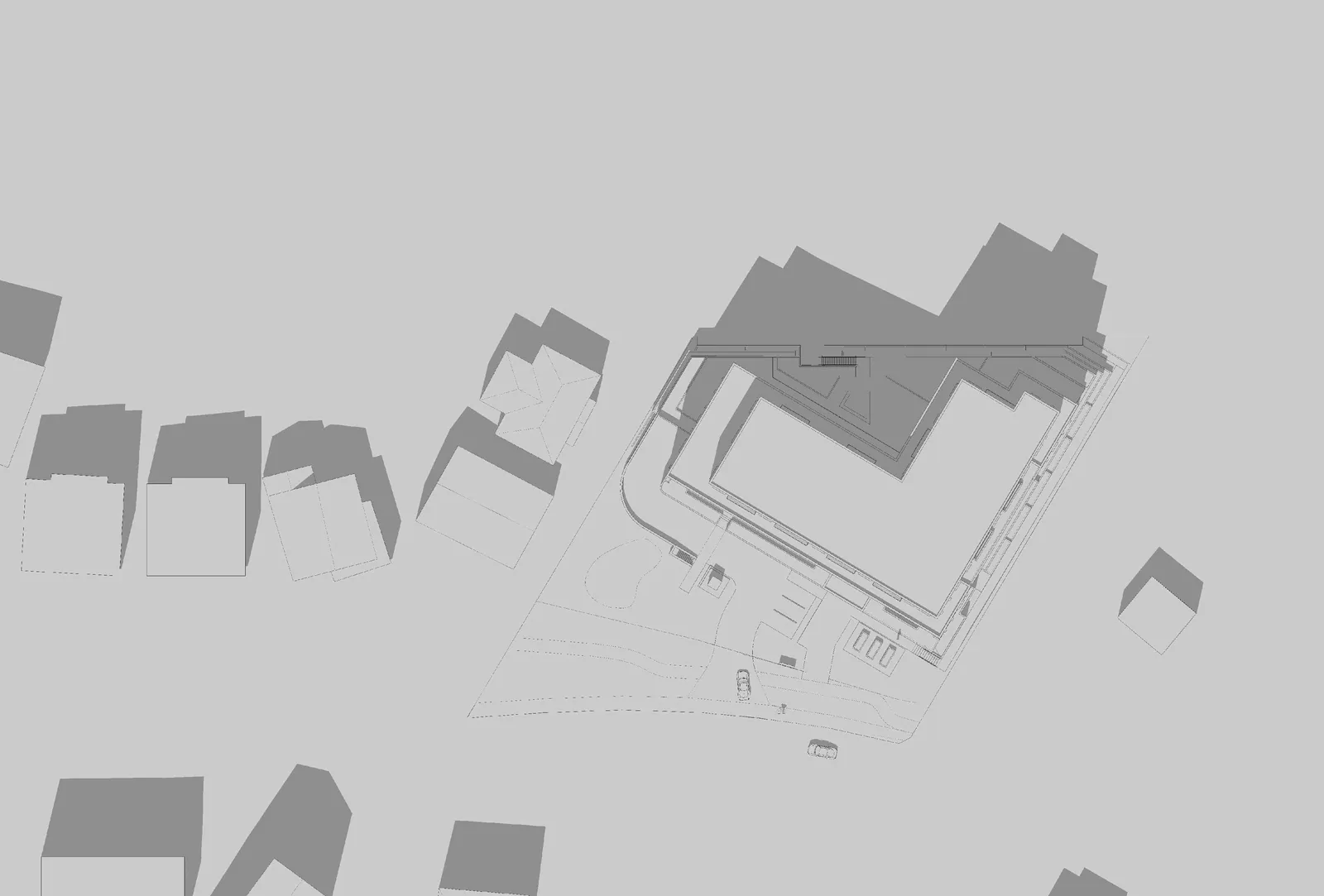
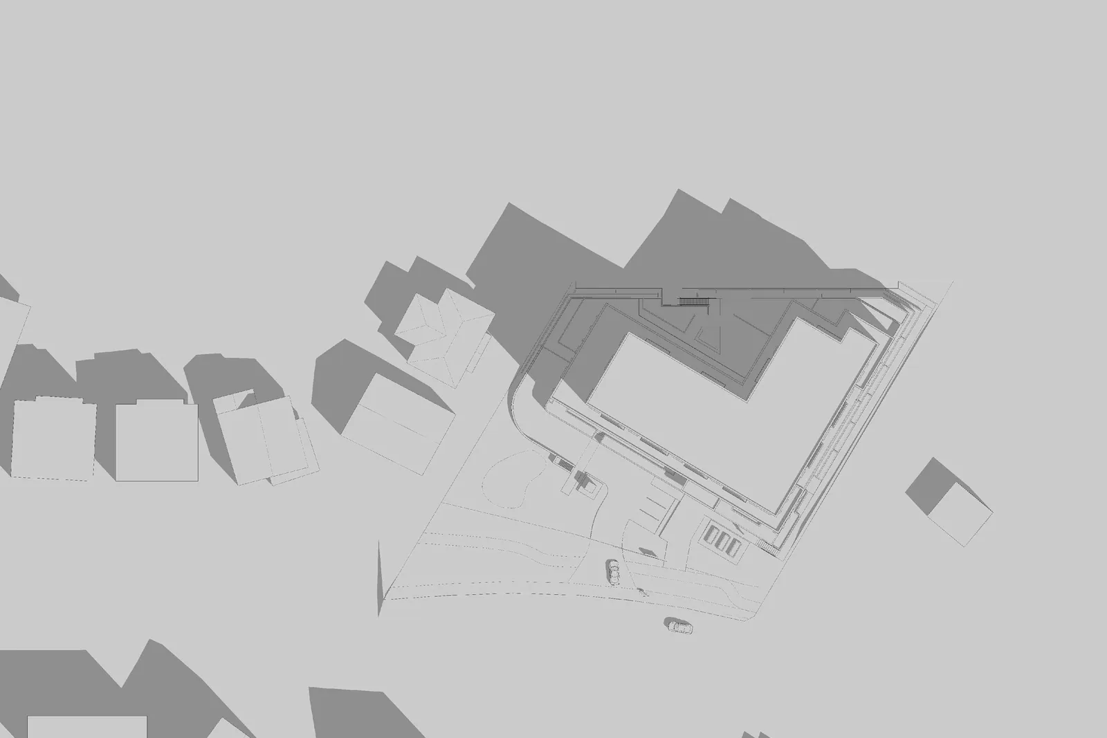
A020 SHADOW STUDY
- SHADOW ANALYSIS - WINTER SOLSTICE (9am)
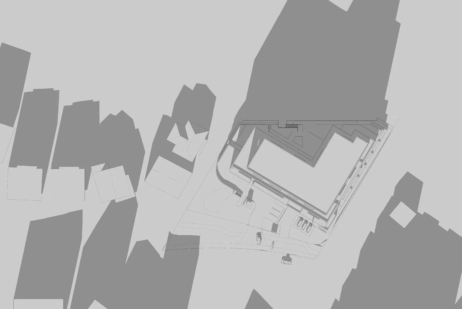
- SHADOW ANALYSIS - WINTER SOLSTICE (NOON)
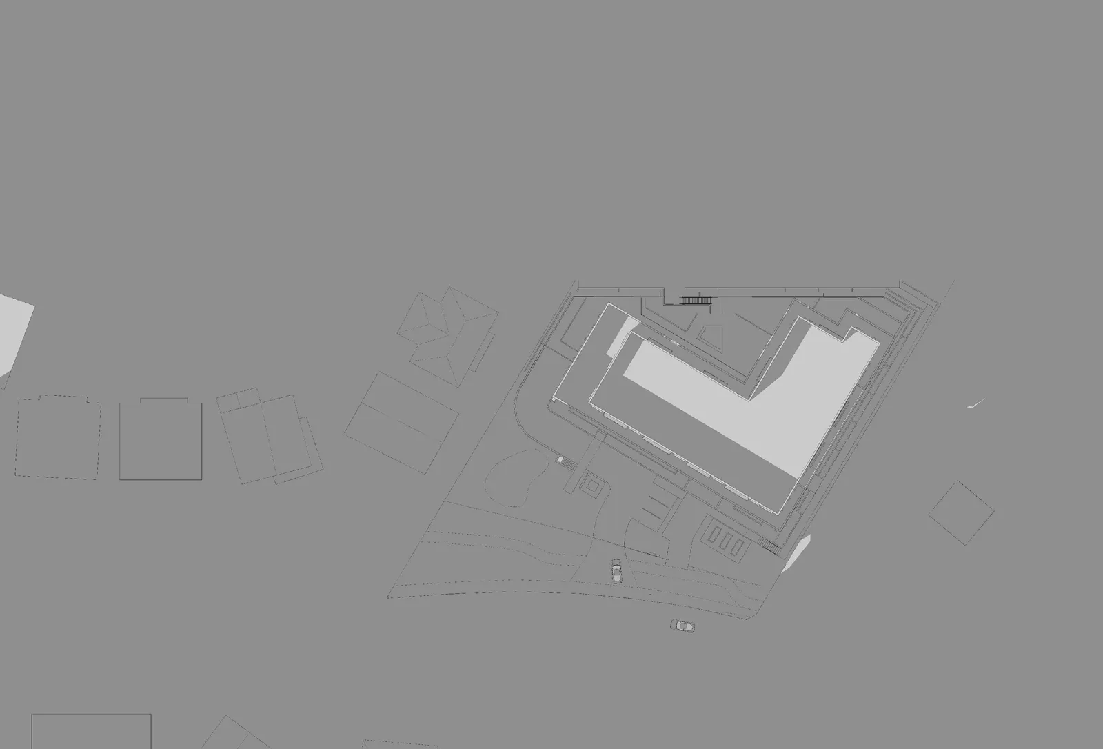
- SHADOW ANALYSIS - WINTER SOLSTICE (3pm)
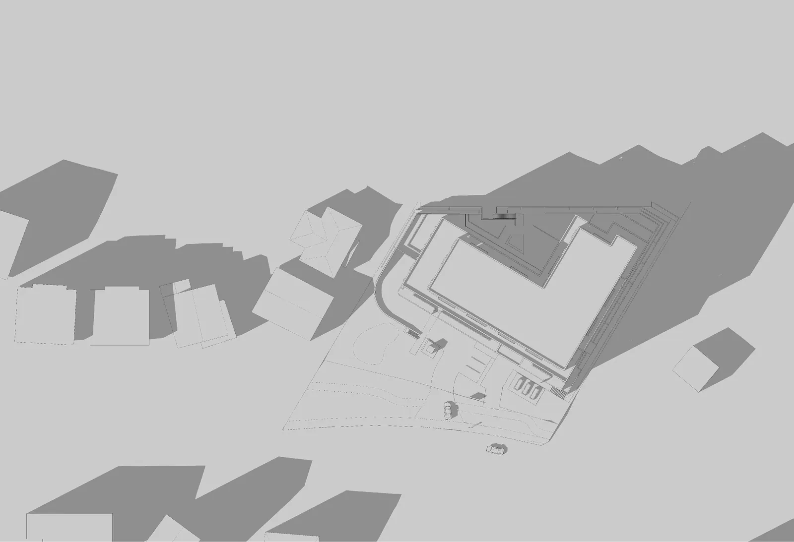
- SHADOW ANALYSIS - EQUINOX (9am)
- SHADOW ANALYSIS - EQUINOX (NOON)
- SHADOW ANALYSIS - EQUINOX (3pm)
Page 7: Material Palette
A021 MATERIAL PALETTE
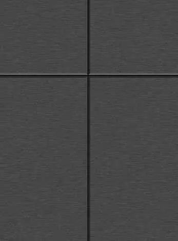
- 1.0 SIDING: Painted Fibre Cement Panel w/ Painted Trims. Colour: Charcoal. Location: Recessed Balconies (Level 5-6).
- 1.0 SIDING: Painted Fibre Cement Panel w/ Painted Trims. Colour: Medium Grey. Location: Recessed Balconies (Level 1-4).
- 2.0 SIDING: Painted Horizontal Fiber Cement Siding (6" Exposure). Colour: Medium Grey. Location: Level 1-4.
- 2.1 SIDING: Painted Fibre Cement Panel w/ Painted Trims. Colour: Medium Grey. Location: Recessed Balconies (Level 1-4).
- 3.0 SIDING: Metal Panel. Colour: White. Location: Level 1-4.
- 3.1 SIDING: Metal Panel. Colour: Charcoal. Location: Level 5-6.
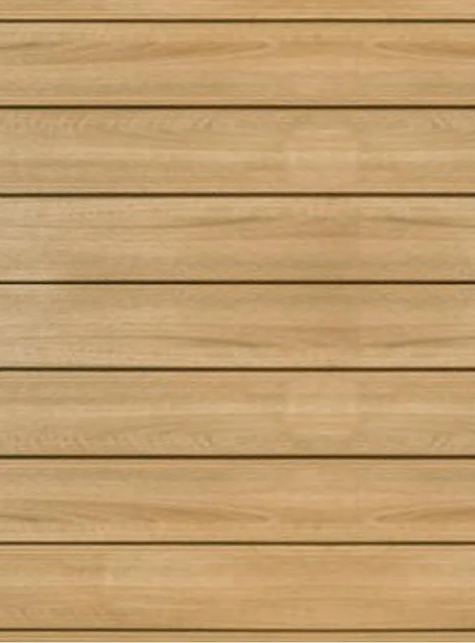
- 4.0 SIDING + SOFFITS: Woodgrain Metal Soffit and Siding. Colour: Cedar. Location: Balcony/Roof Soffit, Balcony Wall.
Cedar woodgrain sample. - 5.0 GUARDRAILS: Aluminum Picket Guardrail. Colour: Charcoal. Location: Level 1-4, 6.
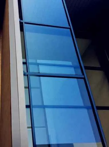
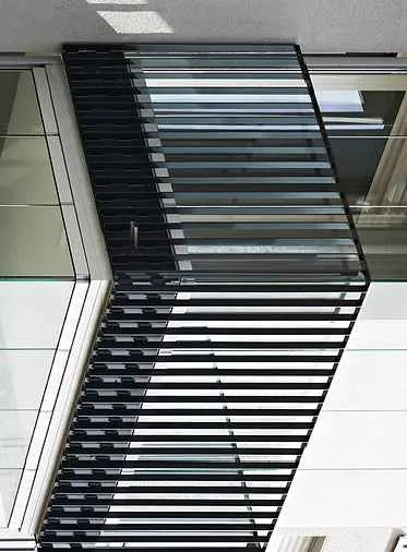
- 5.1 GUARDRAILS: Glass Guards with Aluminum Stanchions and Rails. Colour: Clear Glass / Charcoal Aluminum. Location: Level 2 (Above Residential Entry), Level 5. [Image 172-173: Guardrail material samples.]
- 6.0 RESIDENTIAL ENTRY: Aluminum Storefront Windows. Colour: Charcoal. Location: Residential Entrance.
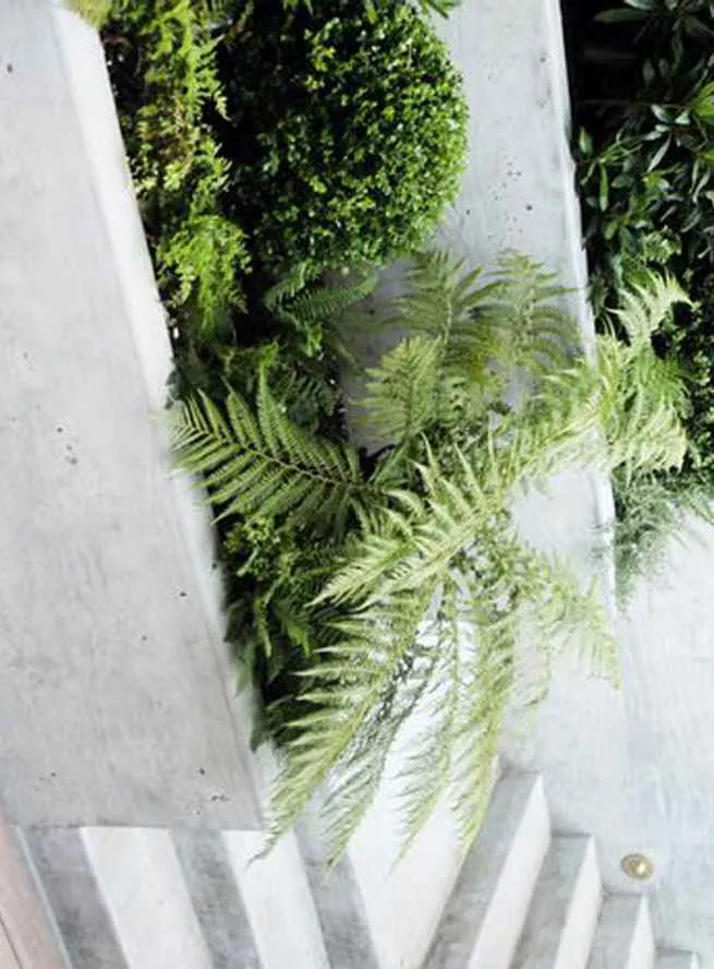
- 7.0 LANDSCAPE PLANTERS: Concrete Landscape Planter. Colour: Concrete Finish. Location: Refer to Landscape Plans.
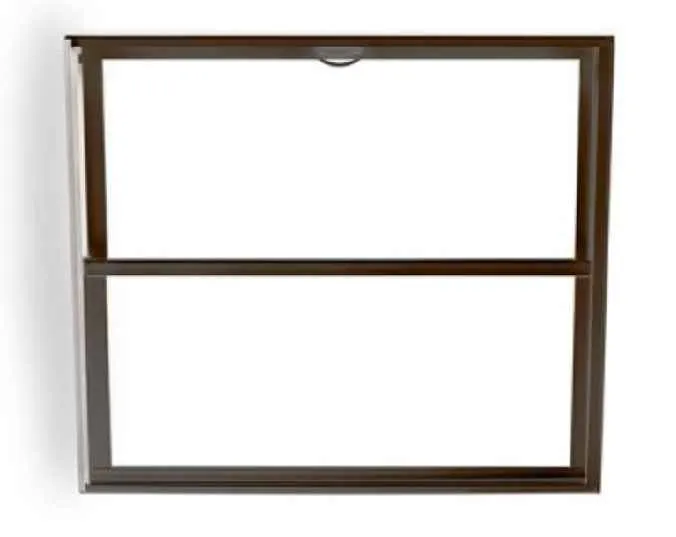
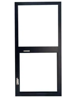
Landscape planter photograph. - 8.0 RESIDENTIAL WINDOWS: Aluminum-Clad Vinyl Windows. Colour: Charcoal. Location: Level 1-6. [Image 176-180: Window material samples.]
- 9.0 BALCONY/PATIO DOORS: Aluminum-Clad Vinyl Patio Doors. Colour: Charcoal. Location: Balconies.
Page 8: Project Views
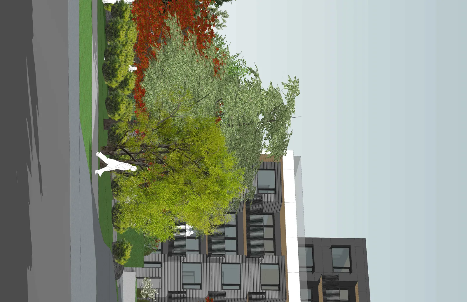
A030 PROJECT VIEWS
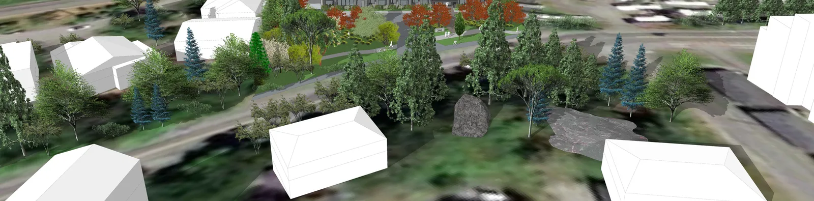
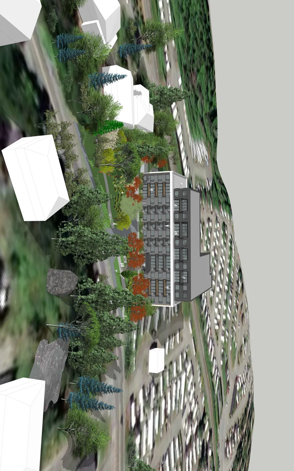
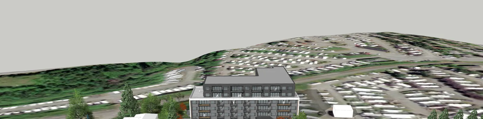
- VIEW 1 - AERIAL LOOKING NORTH
Document Images
(169)