Attachment 9: Conceptual Servicing Brief (McElhanney)
Technical report assessing the capacity of municipal infrastructure to support the proposed development.
CONCEPTUAL SERVICING BRIEF
To: Town of View Royal Engineering Department
From: Nathan Dunlop, P.Eng., Project Engineer, McElhanney Ltd. (Victoria office)
Re: 167/169/171 Island Highway Conceptual Servicing Brief
Date: June 18, 2021
1. INTRODUCTION
The proposed development is located along Island Highway at 167, 169 and 171 Island Highway, in View Royal, BC.
The properties require Rezoning.
This Conceptual Servicing Brief is submitted in support of the Rezoning Application. This brief will provide information on the existing and proposed storm, sanitary and water infrastructure for the proposed development.
2. EXISTING CONDITIONS
2.1. ISLAND HIGHWAY
- Storm:
- 375 mm dia Polyvinyl Chloride (PVC) main along Island Highway, connects to a 600 mm dia Corflo main crossing the road south (near the north-east side of the development). This pipe connects to a 675 mm dia main running through Portage Park.
- Storm connection (size unknown) to 167 Island Highway connects to the 675 mm dia main
- A combined 200 mm dia storm connection to 169 and 171 Island Highway connects to the 375 mm PVC main in the road
- Sanitary:
- 200 mm dia PVC sanitary main
- 200 mm dia PVC road crossing near the north-east side of the development. This connection then splits to provide a service to each of to 167, 169 and 171 Island Highway
- Water:
- 200 mm dia Ductile Iron (DI) distribution main
- 813 mm dia Steel supply main
- combined 50 mm dia Copper water service to 167, 169 and 171 Island Highway
3. DESIGN CRITERIA AND ASSUMPTIONS
3.1. STORM
- Design Criteria:
- Provide post-development runoff equal to or less than pre-development runoff, up to a 1 in 10 year rainfall event.
- Flows above the 1 in 10 year rainfall event will flow overland.
- Assumptions:
- Victoria-Gonzales IDF curve used in the PCWMM model.
3.2. SANITARY
- Design Criteria:
- Sewage flows will be calculated in accordance with the Master Municipal Construction Documents (MMCD) Design Guidelines 2014. As MMCD does not provide per capita rates for residential units, the Sewage Disposal Regulation of the Health Act (Appendix A) will also be utilized.
- Assumptions:
- The occupancy load is based on the number of residential units (and unit mix) as proposed in the Rezoning Applications.
3.3. WATER
- Design Criteria:
- Fire Flows in accordance with the Fire Underwriters Survey (FUS) with 140 kilo Pascals (kPa) or 20 pounds per square inch (psi) of residual pressure.
- Domestic Flows: meter sizing will be based on the American Water Works Association (AWWA) M22 calculation.
- Assumptions:
- The FUS calculation and the AWWA M22 calculations will be based on the building configuration and occupancy load as proposed in the Rezoning Applications.
4. PROPOSED FLOWS AND LOADS
Please refer to the attached Conceptual Servicing drawing dated June 18, 2021 in conjunction with the information below.
4.1. STORM
Storm water from within the development lot will be collected via roof and area drains and connected to the storm water management system. The SWM system will consist of onsite conveyance mains, storm water storage tanks and a flow control manhole. Storm water will be discharged from the site through an orifice controlled outlet into the existing 675 mm dia storm main in Portage Park (existing service size will be confirmed and upsized if required). Storm water discharges will be limited to pre-development runoff rates for the 2- and 10-year events.
All rainfall events greater than a 10-year event will follow the overland flood route to Portage Park.
4.1.1. Stormwater Calculations:
A PCSWMM model was used to calculate pre- and post-development runoff. The model also calculated required storage volumes to maintain post-development runoff at pre-development rates.
4.1.1.1. Model Input Parameters
- IDF Data = Victoria-Gonzales
- Intensity (24 hr 1:2-year storm event) = 44.9 mm / day
- Intensity (24 hr 1:10-year storm event) = 75.3 mm / day
- Rainfall Distribution = SCS Type 1A
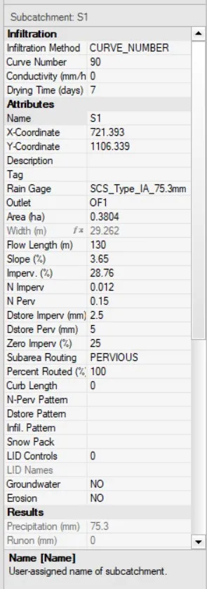
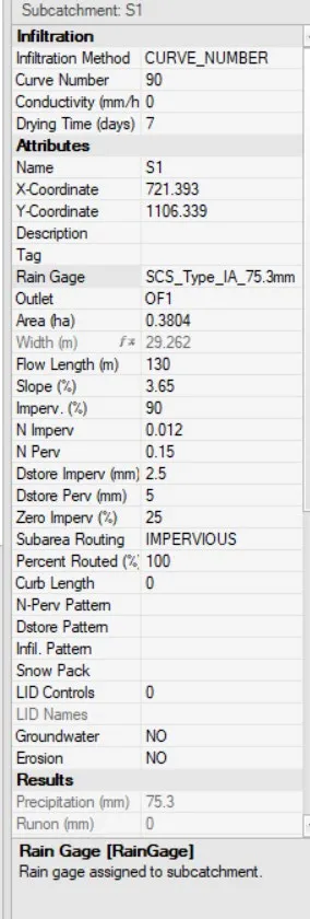
See attached Appendix B for a detailed breakdown of the model input parameters.
4.1.1.2. Model Outputs
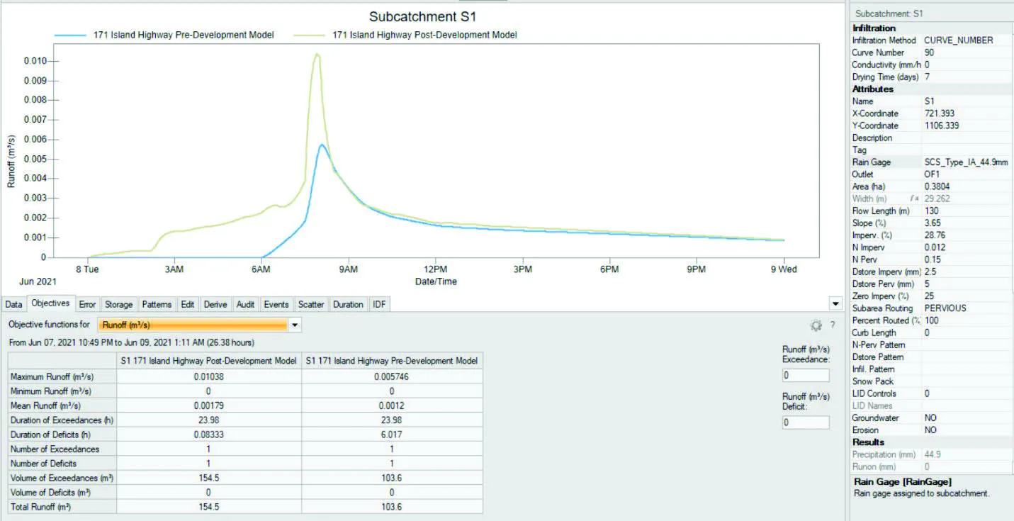
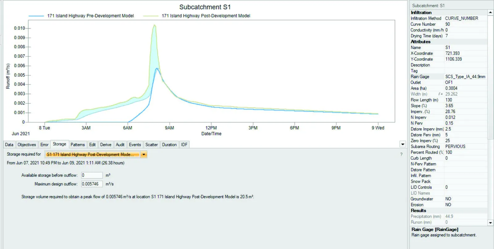
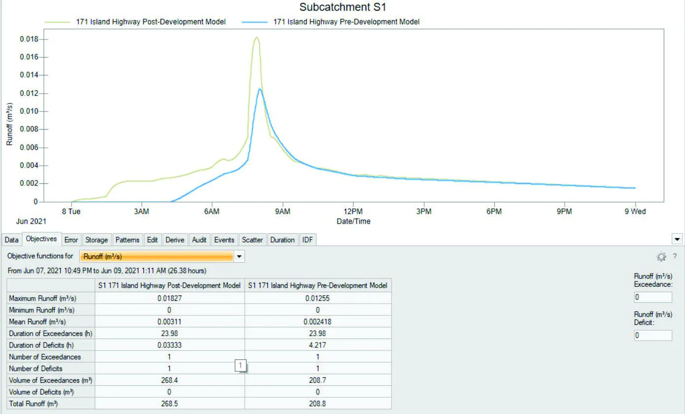
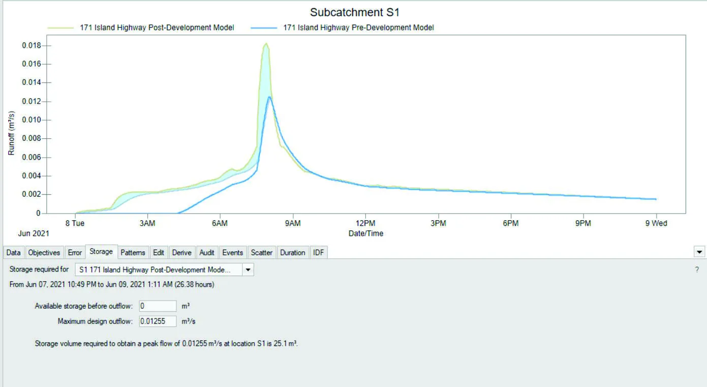
The following is a summary of the model outputs, detailing the pre-development and post-development flows as well as the required storage for both the 2- and 10-year rainfall events. Post-development storage volumes determined limited post-development flows to pre-development levels.
- 2-year rainfall event:
- Pre-development runoff = 5.7 L/s
- Post-development runoff (without flow control) = 10.4 L/s
- Required storage = 20.5 m³
- 10-year rainfall event:
- Pre-development runoff = 12.6 L/s
- Post-development runoff (without flow control) = 18.3 L/s
- Required storage = 25.1 m³
To limit the discharge during the 10-year event, the orifice size in the flow control manhole is to be 84mm diameter. This orifice size is a function of the stormwater storage facility used and will be confirmed during detailed design.
See attached Appendix C for a detailed breakdown of the model outputs.
4.2. SANITARY
The proposed flows including residential, peaking factor and infiltration is approximately 2.08 L/s. Please refer to Appendix D for detailed calculations.
There is an existing sanitary main along Island Highway that also has an existing 200 mm diameter sanitary service crossing Island Highway. This crossing (from SMH 128 to SMH 117) is located near the north-east corner of 167 Island Highway. It is proposed that flows from the development connect to this existing service.
The elevation of SMH 128 is approximately 8.7m so any onsite sanitary system that cannot flow by gravity to that location / elevation will require pumping.
View Royal is to review the sanitary calculation and confirm that the existing system has adequate capacity.
4.3. WATER
When reviewing fire flow coverage for a given development, both the available flow in the water system and maximum velocity through the water system during a fire is analysed:
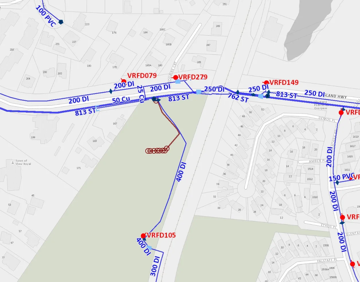
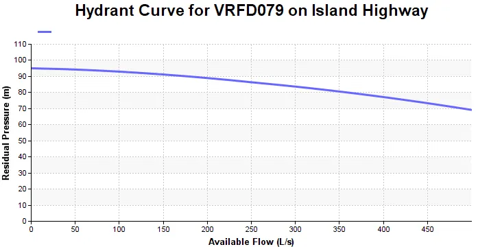
- The available flow for the site, not accounting for velocity, has been provided by the CRD Water Services (see Appendix E). The hydrant data for Hydrant #VRFD079 indicates a maximum flow is over 450 Litres per second (L/s) at a pressure of 20 pounds per square inch (psi).
- The maximum available flow through a 200mm diameter main, with flows from two directions, is 240 L/s. This corresponds to a maximum velocity of 3.5 meters per second (m/s).
A Fire Underwriter’s Survey (FUS) demand is a function of the building construction materials, fire zone areas, separation distances and the use of sprinklers. An FUS calculation was completed, based on the parameters of the proposed building, which indicates a required fire flow of approximately 193 L/s (Appendix F). Final FUS calculation will be completed / confirmed during detailed design.
Since the FUS calculation (ie. the required fire flow) is less than the available flow provided by the CRD with a residual pressure of 20 psi and the velocity through the water main is less than 3.5 m/s during that fire flow, it appears the existing system can satisfy the demand.
The CRD is to review the FUS calculation and confirm that the existing system has adequate fire flow capacity.
The available flow for the domestic water demand can be satisfied if the demand for the fire flow is achieved.
5. CONCLUSION
Based on the current design and the available information, it appears the development can be serviced. The assumptions and flows should be reviewed by the CRD and View Royal to ensure adequate offsite capacities.
This report was completed by McElhanney Ltd.
Nathan Dunlop, P.Eng.
Project Manager
Ian McCall, P.Eng.
Senior Project Engineer
[Conceptual Servicing site plan drawing for 171 Island Highway]
APPENDIX A: MINISTRY OF HEALTH SEWAGE DISPOSAL REGULATION
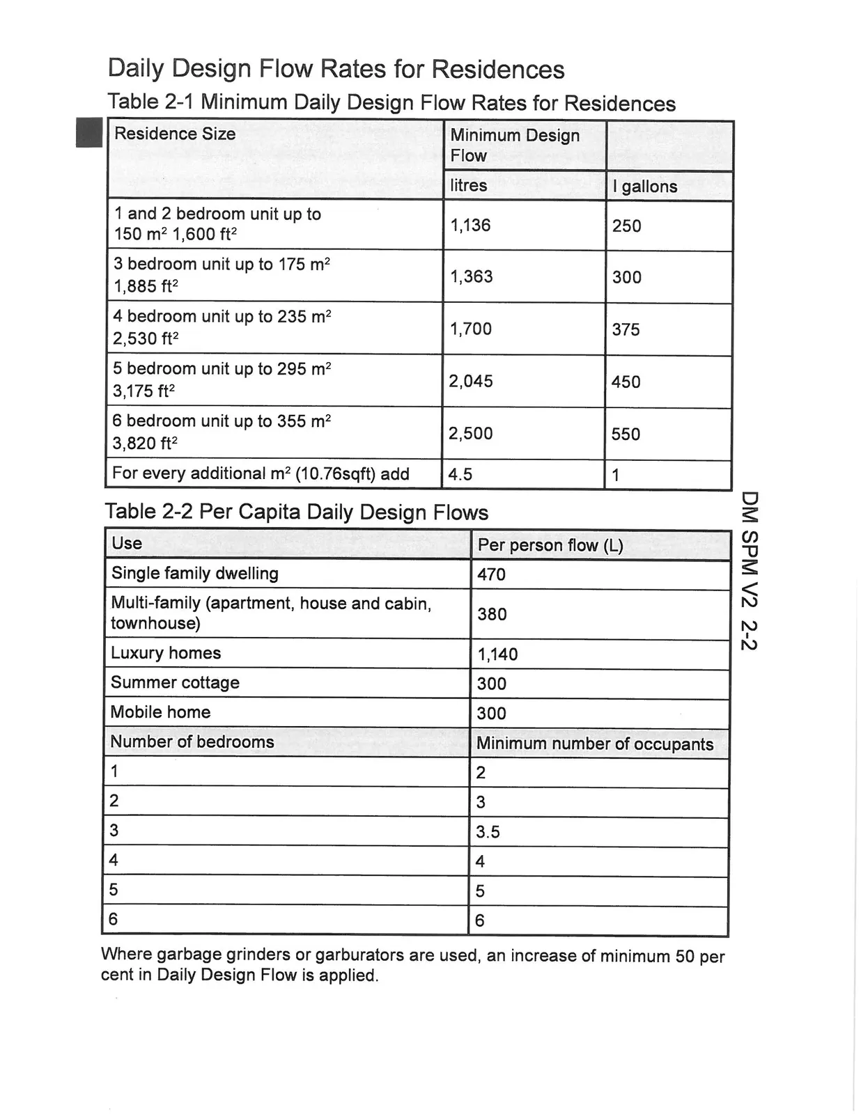
Table 2-1 Minimum Daily Design Flow Rates for Residences
| Residence Size | Minimum Design Flow (litres) | Minimum Design Flow (I gallons) |
|---|---|---|
| 1 and 2 bedroom unit up to 150 m² 1,600 ft² | 1,136 | 250 |
| 3 bedroom unit up to 175 m² 1,885 ft² | 1,363 | 300 |
| 4 bedroom unit up to 235 m² 2,530 ft² | 1,700 | 375 |
| 5 bedroom unit up to 295 m² 3,175 ft² | 2,045 | 450 |
| 6 bedroom unit up to 355 m² 3,820 ft² | 2,500 | 550 |
| For every additional m² (10.76sqft) add | 4.5 | 1 |
Table 2-2 Per Capita Daily Design Flows
| Use | Per person flow (L) |
|---|---|
| Single family dwelling | 470 |
| Multi-family (apartment, house and cabin, townhouse) | 380 |
| Luxury homes | 1,140 |
| Summer cottage | 300 |
| Mobile home | 300 |
| Number of bedrooms | Minimum number of occupants |
|---|---|
| 1 | 2 |
| 2 | 3 |
| 3 | 3.5 |
| 4 | 4 |
| 5 | 5 |
| 6 | 6 |
Where garbage grinders or garburators are used, an increase of minimum 50 per cent in Daily Design Flow is applied.
APPENDIX B: PCSWMM STORM WATER MODEL INPUT PARAMETERS
2-year storm pre-development attributes:
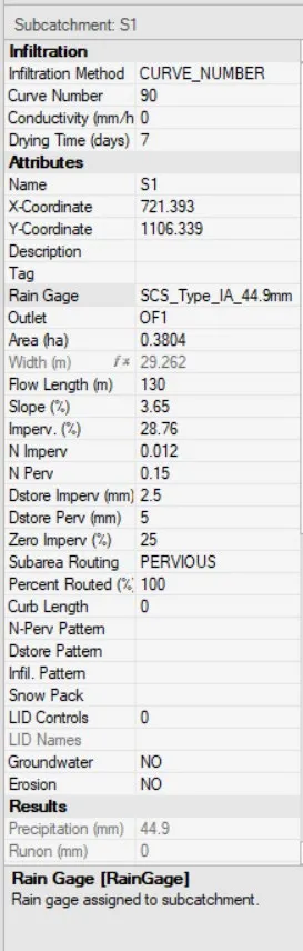
2-year storm post-development attributes:
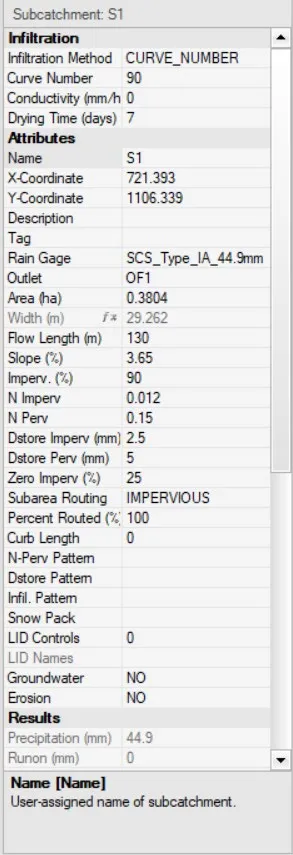
10-year storm pre-development attributes:
10-year storm post-development attributes:
APPENDIX C: PCSWMM STORM WATER MODEL OUTPUT RESULTS
2-Year Storm:
10 year storm:
APPENDIX D: ESTIMATED SANITARY FLOWS
Estimated Sanitary Flow (Proposed - Residential)
Project: 167 / 169 / 171 Island Highway, View Royal, BC
Date: June 18, 2021
Client: GT Mann Contracting Ltd.
McElhanney File #: 21-060 (4)
| Estimated Residential flow | Value | Units/Notes |
|---|---|---|
| Total units* | 87 | |
| TOTAL RESIDENTIAL UNITS | 87 | |
| Persons per unit** | 2.21 | Estimated |
| Equivalent Population | 192 | capita |
| Per Capita Flow Rate*** | 240 | L/capita/day |
| Average flow = | 46,080 | L/day |
| Average Daily Flow | 46,080 | L/day |
| 0.533 | L/s | |
| Peaking Factor**** | 3.81 | |
| Estimated Peak Flow = | 2.03 | L/s |
| Site Area = | 3,804 | sq.m. |
| Approx. Hard Surface building area = | 0 | sq.m. |
| Approx. area for infiltration (allows for entire site infiltration) = | 3,804 | sq.m. |
| Inflow and Infiltration (0.12 L/s/ha)***** | 0.046 | L/s |
| Total Estimated Flow = Estimated Peak Flow + Inflow and Infiltration | 2.08 | L/s |
* based on information provided by Urban West Architecture Inc. dated June 18, 2021
** based on Ministry of Health Sewerage System Standard Practice Manual (Table II-9 - Per Capita Daily Design Flow for Residences)
*** based on MMCD Design Guideline Manual 2014 (Section 3.2 Per Capita Flow, dry weather)
**** based on MMCD Design Guideline Manual 2014 (Section 3.4 Peaking Factor)
***** based on MMCD Design Guideline Manual 2014 (Section 3.5 Infiltration - used old system requirement to provide factor of safety)
People per unit calculation:
| Unit Type | Units | Cap/unit | Capita |
|---|---|---|---|
| Number of 4 bedroom units | 0 | 4.5 | 0 |
| Number of 3 bedroom units | 4 | 3.75 | 15 |
| Number of 2 bedroom units | 11 | 3 | 33 |
| Number of 1 bedroom units | 72 | 2 | 144 |
| Number of studio units | 0 | 1.25 | 0 |
| TOTAL | 87 | 192 | |
| Therefore, Persons per unit = total capita/total units = | 2.21 |
APPENDIX E: CRD WATER INFORMATION
APPENDIX F: FUS FIRE FLOW CALCULATION
Fire Flow Calculation - based on Underwriters Guide, 1999
167, 169, 171 Island Highway, View Royal, BC
Type of Construction:
C = 1.30 (Reduce for non-combustible siding and roofing)
- 1.5 Wood Frame - structure essentially all combustible
- 1 Brick or masonry walls - ordinary construction
- 0.8 Unprotected metal structural components - non combustible
- 0.6 Fully protected frame, floor, roof - fire resistive
Finished Floor area:
A = 6148 sq.m (66175 sq.ft)
Estimated Fire-Flow:
- F = 220 * C * (A^1/2)
- F = 22425 L/min
- F = 22000 L/min (Rounded to nearest 1000)
- F = 366.7 L/s
The Estimated Fire-Flow above can potentially be reduced as follows:
Occupancy:
- % = -25 % (Non-combustible)
- Amount of Fire-Flow reduction (Occupancy): F = -91.7 L/s
- Estimated Reduced Fire-Flow (Occupancy): F = 275.0 L/s
Sprinkler Protection:
- % = -50 % (Fully automated sprinklers)
- Amount of Fire-Flow reduction (Sprinkler): F = -137.5 L/s
Exposure Separation:
| # of sides | Separation (meters) | Charge % | Notes |
|---|---|---|---|
| 0 | 0 - 3 | 0 | |
| 0 | 3.1 - 10 | 0 | |
| 0 | 10.1 - 20 | 0 | |
| 1 | 20.1 - 30 | 10 | Six mille pub to the west |
| 2 | 30.1 - 45 | 10 | View Royal municipal hall to the south and house across the road to the north |
| 1 | 45+ | 0 | park to the east |
| 4 | 20 % | (75% max) |
- Exposure Separation charge: F = 55.0 L/s
Estimated Fire-Flow (with reductions & charges)
- F = 192.5 L/s
TOTAL FUS FIRE-FLOW COVERAGE REQUIRED:
F = 192.5 L/s (11550.0 L/min)
Building area provided by Urban West Architecture Inc.
2021-06-18 21-060-FUS calculation.xls
6/16/2021