STORM WATER MANAGEMENT PLAN for Eagle Nest Residences
Technical report outlining the drainage conditions and the proposed strategy for managing stormwater runoff using rain gardens and detention systems.
STORM WATER MANAGEMENT PLAN
for Eagle Nest Residences (#3 & 5 Helmcken Road and #1449 Burnside Road, View Royal)
Prepared for: Helmcken Rd Development BC Ltd. #200 – 1501 First Street SW Calgary, AB T2R 0W1
Prepared by: McElhanney Ltd. #500 – 3960 Quadra Street Victoria, BC V8X 4A3
Date: October 28, 2021
Table of Contents
- Introduction................................................................................................................................................... 3
- Existing Conditions ........................................................................................................................................ 4
- General Storm Water Management Approach ............................................................................................. 5
- Storm Water Management Strategy ............................................................................................................. 5 4.1. Natural, Revegetated and Landscaped Areas ....................................................................................... 5 4.2. Building and Hardscaped (Non-vehicular) Areas................................................................................... 5 4.3. Hardscaped (Vehicular Accessible) Areas.............................................................................................. 6
- Stormwater Quantity Control........................................................................................................................ 6 5.1. Pre-development Runoff....................................................................................................................... 6 5.2. Post Development Runoff ..................................................................................................................... 7 5.3. Stormwater Detention........................................................................................................................... 8
- Stormwater Quality (Treatment)................................................................................................................... 8
- Erosion and Sediment Control During Construction ..................................................................................... 8 7.1. Silt Fences-Perimeter Ditching .............................................................................................................. 9 7.2. Sediment Control Ponds...................................................................................................................... 10 7.3. Slope and Surface Protection .............................................................................................................. 10
1. Introduction
McElhanney Ltd. (McElhanney) has been retained by Helmcken Rd. Development BC Ltd. (Client) to provide a Storm Water Management Plan for the properties located at 3 and 5 Helmcken Road and 1449 Burnside Road in the Town of View Royal.
The purpose of this report is to support an application for a redevelopment on the subject property.
The development combines the three existing lots into one 1.38-hectare property. The development will include:
- 3 – four to six storey residential multi-unit buildings
- Under building parking
The site is bounded to the east and north with undeveloped land (farms). The lots to the south and west are residential townhomes and single-family dwellings.
This Storm Water Management Plan will:
- Review the existing surface drainage conditions.
- Consider the approach to be used for storm water management.
- Describe a proposed storm water management strategy.
2. Existing Conditions
The existing site includes a residential apartment building and a couple of single family dwellings, see Figure 1.
The terrain generally slopes to the south west, from 1 to 5%, away from Burnside Road. There is an existing rock knoll near the south west corner.
Surface drainage from adjacent properties do not appear to discharge onto the property. Road drainage along Burnside Road generally flows to roadside ditches which connect to a municipal drain system. There appear to be unrecorded storm drains in the area connecting drainage from Burnside Road to Helmcken Road. Additional investigation such as camera inspection or ground penetrating radar may be required to determine details of the existing municipal drainage system.
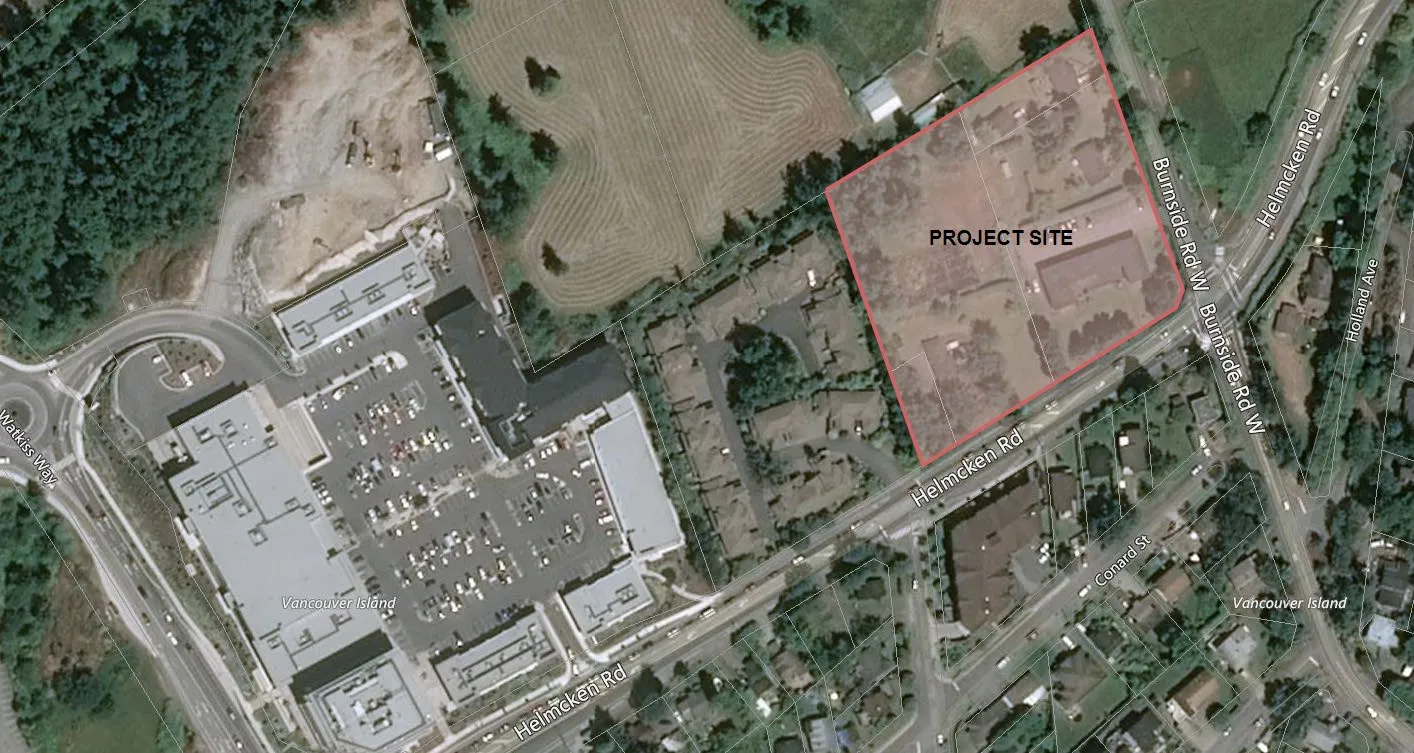
Figure 1: Project Site
3. General Storm Water Management Approach
The proposed developments’ Storm Water Management Plan will be a collaboration between the design professionals (Civil Engineer, Arborist, Landscape Architect, Geotechnical Engineer) and the Town of View Royals staff (Engineering, Parks, Planning). The approach taken will address and promote the following:
- Detain post-development runoff to pre-development runoff rates
- Provide storm water systems that promote ground water recharge
- Minimize impacts to storm water quality
- Minimize sedimentation and erosion, stabilize and re-vegetate impacted areas
- Consider impacts of extreme rainfall (1 in 200 year) events
4. Storm Water Management Strategy
The proposed storm water management facilities will separate rainfall on the development into three general categories:
- Natural, Revegetated and Landscaped areas
- Building and Hardscaped (non-vehicular) areas
- Hardscaped (vehicular accessible) areas
4.1. Natural, Revegetated and Landscaped Areas
Rainfall runoff in these areas will be encouraged to follow the natural terrain of the area and infiltrate into the ground. No additional runoff from pre-development conditions anticipated for these areas.
4.2. Building and Hardscaped (Non-vehicular) Areas
Rainfall runoff in these areas will be directed to area drains and landscaped area. The runoff will ultimately be directed to either of the two proposed rain gardens for detention, prior to discharge to the municipal drainage system with orifice-controlled outlets to limit flows to the 2 and 10-year existing (pre-development) rates. The intent is to utilize rain gardens to promote infiltration (to the extent possible given the soil conditions) and provide detention. Designed overflow facilities will be provided for events greater than 10-year return. Major storm events (200-year event) will be directed overland.
4.3. Hardscaped (Vehicular Accessible) Areas
Rainfall runoff in these areas will be directed to area drains and routed through oil / water separators. The runoff will ultimately be directed to either of the two proposed rain gardens for detention, prior to discharge to the municipal drainage system with orifice-controlled outlets to limit flows to the 2 and 10-year existing (pre-development) rates. The intent is to utilize rain gardens to promote infiltration (to the extent possible given the soil conditions) and provide detention. Designed overflow facilities will be provided for events greater than 10-year return. Major storm events (200-year event) will be directed overland.
Minor regrading of the existing ditch along Burnside Road is proposed. Road runoff from Burnside Road will be directed to this ditch via curb cutouts.
5. Stormwater Quantity Control
5.1. Pre-development Runoff
Calculation of the pre-development runoff is contingent on the site’s runoff coefficient value. As shown on Figure 1, the pre-development condition of the site was a mix of flat undeveloped areas, rock knoll, buildings, and gravel / asphalt driving surfaces.
Typical C Coefficients*
| Description of Area | Runoff Coefficients Range | Runoff Coefficients Selected | Contributing Area (m²) | C x A |
|---|---|---|---|---|
| *Asphalt (d/w, parking) | 0.70 - 0.95 | 0.95 | 1160 | 1102 |
| *Gravel (d/w, paths) | 0.75 | 0.75 | 1200 | 900 |
| *Buildings | 0.75 - 0.95 | 0.95 | 970 | 922 |
| *Lawns, Average 2-7% | 0.18 – 0.20 | 0.20 | 9630 | 1926 |
| *Rock knoll, 10-30%, tree cover | 0.75 | 0.75 | 800 | 600 |
| Contributing Area (ha) = | (13760 m²) 1.38 ha | |||
| Pre-development C = | 0.40 |
Based on the Rational Method, the resultant pre-development flows from the site are calculated based on the following:
Q=ciA/360
Where
- “i” 2-year 15 min = 13.4 mm/hr
- “i” 10-year 15 min = 20.9 mm/hr
- “c” = 0.40
- “A” = 1.38 ha
Pre-development Q₂ = 0.020 m³/s (2.0 l/s) Pre-development Q₁₀ = 0.032 m³/s (3.2 l/s)
5.2. Post Development Runoff
Following development, substantial portions of the site will have been excavated and regraded to provide level areas for the buildings (footprints), driveway, sidewalks, and landscape areas. Undeveloped areas will be graded to match the existing grade at property lines. Similar to the pre-development calculations above, the following table calculates the post-developed site’s runoff coefficient.
Typical C Coefficients*
| Description of Area | Runoff Coefficients Range | Runoff Coefficients Selected | Contributing Area (m²) | C x A |
|---|---|---|---|---|
| *Asphaltic | 0.70 - 0.95 | 0.95 | 1460 | 1387 |
| *Concrete (d/w, s/w) | 0.80 - 0.95 | 0.95 | 1200 | 1140 |
| *Buildings | 0.75 - 0.95 | 0.95 | 4530 | 4304 |
| *Lawns, Average 2-7% | 0.18 – 0.22 | 0.20 | 6570 | 1314 |
| Contributing Area (ha) = | (13760 m²) 1.38ha | |||
| Post Development C (rounded) = | 0.60 |
Post-development Q₂ = 0.031 m³/s (3.1 l/s) vs Pre-development Q₂ = 0.020 m³/s (2.0 l/s) Post-development Q₁₀ = 0.048 m³/s (4.8 l/s) vs Pre-development Q₁₀ = 0.032 m³/s (3.2 l/s)
As expected, with the post-development runoff coefficient greater than that of the pre-development, the resultant post-development flows are higher. As such, storm water detention with flow-controlled release is proposed to reduce the 2- and 10-year rainfall event peak runoff rates to match pre-development levels.
5.3. Stormwater Detention
The development is proposing two rain gardens, each with an orifice-controlled outlet to restrict the post-development runoff to the peak pre-development runoff rates. The size of the orifices will be determined during detailed design as it is directly related to the onsite grading and contributing area to each rain garden.
The minimum required total detention volume, based on the controlled release rates and calculations above, are:
- 13.5 cu.m. for 1 in 2-year storm events
- 21.1 cu.m. for 1 in 10-year storm events
Based on the preliminary design, the rain garden near the Helmcken Road and Burnside Road intersection will have a storage volume of ~ 20 cu.m. (not including the detention within the soil) and the western rain garden along Helmcken Road will have a storage volume of ~ 8 cu.m. (not including the detention within the soil). These volumes exceed the necessary volume noted above.
6. Stormwater Quality (Treatment)
Storm water from the developments hardscaped (vehicular access) areas will be treated through oil / water separators prior to entering the storm water infiltration / detention system.
7. Erosion and Sediment Control During Construction
A key factor in erosion and sediment control is the interception and management of site runoff. Careful planning of construction site activities and phasing, to prevent the generation of erosion, is more effective and less expensive than downstream sediment control with sediment ponds only. Sediment ponds should be considered the last line of defense.
As outlined in the "Land Development Guidelines for Protection of Aquatic Habitat", the following general principles will be required at this site:
- Where possible, conduct earthworks activities during dry months of the year
- Stage activities to allow "green-up" or re-establishment of vegetation and minimize bare areas
- Halt construction during periods of significant precipitation and runoff
- Restrict vehicular/equipment access or provide working surfaces/roads. At each access point to the development site, a sediment pond or trap should be constructed to retain wash down water and sediments that may flow down the adjacent catchment to the access point.
- Retain existing vegetation until excavation commences, i.e. do not strip vegetation long before the following activities
- Minimize clearing and stripping areas
- Physically mark clearing boundaries on the construction site
- Seed or re-vegetate cut and fill slopes, and disturbed natural areas
- Cover temporary fills or stockpiles with sheeting or tarps and/or use silt fence surround
- Use mulches and other organic stabilizers to minimize erosion until
- Vegetation is established
- Plan seeding and planting to allow establishment before the end of the growing season
The following site-specific control measures are suggested to be included when the contractor produces the Erosion and Sediment control plan:
7.1. Silt Fences-Perimeter Ditching
Silt fences provide an effective filter for sediment laden runoff from bare soil slopes and surfaces. Silt fences are effective boundary control devices, trapping the sediment close to the erosion source and reducing the mobilization into runoff.
Silt fences should be installed along the downstream edges of activity, lower property lines and at the top of the slope to the foreshore. In temporary runoff control ditches and in proposed bio-swales, silt fences may be overwhelmed by the quantity of runoff and should be reconsidered, in favour of traps or rock berms, particularly where ditch slopes are steeper than approximately 3%.
Adequacy of the silt fence locations should be confirmed in the field, inspected and maintained on a regular basis as construction proceeds.
7.2. Sediment Control Ponds
Sediment control ponds are the last line of defense before runoff is discharged from the development site. Sediment ponds should ideally be a minimum of 1% of the contributing catchment area and be as large as practical within the topographical constraints of the site. Catchment boundaries and proposed locations of the sediment ponds will be shown on the detailed design drawings. Adequacy of the proposed sediment ponds should be reviewed in the field.
7.3. Slope and Surface Protection
The required protection will be determined by the type of material, the grade of slope, and the expected exposure time, and shall be in accordance with the "Land Development Guidelines for Protection of Aquatic Habitat".
In dry conditions, all cut/fill and cleared natural slopes and surfaces should have erosion controls implemented within 14 days.
In wet conditions, erosion control should be implemented immediately on completion of the grading operations of the area.
Slopes exceeding 3.0 meters in height and steeper than 2H:1V should be reviewed by a Professional Engineer, to assess slope stability, erosion, and drainage control requirements.
This report has been prepared by:
McELHANNEY CONSULTING SERVICES LTD.
Ian McCall, PEng, Project Manager imccall@mcelhanney.com 250 370-9221
Date: 2021-10-29
Document Images
(4)