Attachment 6: Geotechnical Documentation Package
A compiled attachment repeating the geotechnical reports, setbacks sketches, and site plans for formal inclusion in the package.
GEOTECHNICAL FIELD REVIEW / SITE INSTRUCTION
Project No: 7439-1 Project: Proposed Subdivision Project Address: 221 Atkins Road – View Royal, BC Date: November 24, 2020 Client: David McAllister Contact: As above Email: davmca@yahoo.com
Distribution: Stantec – Keith Provan – keith.provan@stantec.com Gye and Associates – Jermey Gye – jgye@gyeandassociates.ca
Lot 1 Stability Assessment
As requested, we have carried out additional slope stability analyses to determine safe building setbacks within Lot 1 given new excavation constraints directed by the project arborist. The following summarizes the results of our analyses.
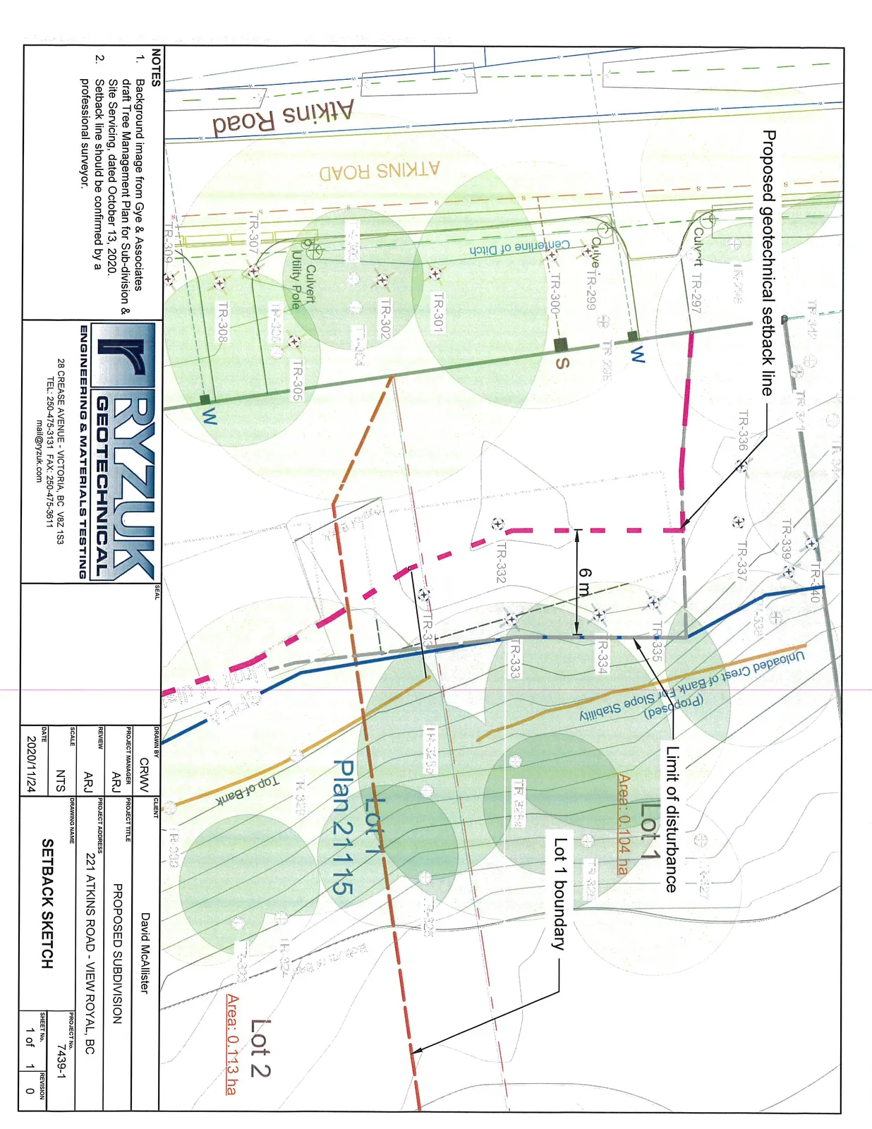
We understand that in order to maintain tree health for the protected trees within the Streamside Protection and Enhancement Area (SPEA), is it not permissible to disturb any soil beyond the "Limit of disturbance" line as shown on the draft drawing "Tree Management Plan for Sub-division & Site Servicing" from Gye & Associates, dated October 13 2020. As such, unloading along the slope crest would be limited to approximately 2.0 m below existing lot grades as opposed to the previously considered 3.5 m.
In order to assess the slope stability condition given 2.0 m of unloading, a stability analysis was conducted using the Software Slide 2 Modeler by Rocscience (version 9.005). Our analysis was carried out in conformance with Engineers and Geoscientists British Columbia (EGBC) guidelines for Legislated Landslide Assessments. The results of our analyses indicate that a setback of 6 m can be maintained from the crest of the unloaded slope (i.e. 6 m setback from the SPEA/Limit of disturbance line). The geotechnical setback can follow the Limit of disturbance line where parallel with the north property boundary. The attached Setback Sketch drawing shows the approximate delineation of the recommended geotechnical setback within Lot 1. We note that the above setback considers a residential structure utilizing conventional shallow spread foundations. It may be possible to construct the residence within the 6 m setback if an alternative foundation approach is considered (i.e. deep foundations). Details for such can be made available upon request.
Excavation works associated with slope unloading and site preparations should be carried out with care in accordance with recommendations from a Qualified Professional. Excavation cutslopes should be prepared in a stable configuration to ensure stability over the short to medium term in the event that the lots are not be developed immediately following excavation. We expect that temporary cutslopes configured at 1 Horizontal to 1 Vertical would be stable, although such should be confirmed at the time of excavation.
If there are any questions or comments with respect to the above, please contact us.
Regards, Ryzuk Geotechnical
Colden Van Ommen, EIT Advanced Junior Engineer
Andrew Jackson, P.Geo./Eng.L. Project Geoscientist / Engineering Licensee
Attachments – Sheet 1: Setback Sketch
The above does not constitute approval to proceed with the noted work if the work is perceived to be an extra to the Contract. Such can only be authorized by the Contract Manager.
Geotechnical Field Review / Site Instruction
Project No: 8-7439-1 Project: Proposed Subdivision - 221 Atkins Road - View Royal, BC Client: David McAllister Email / Fax No: davmca@yahoo.com Date: March 5, 2019
Slope Stability Assessment – Addendum Revision 1
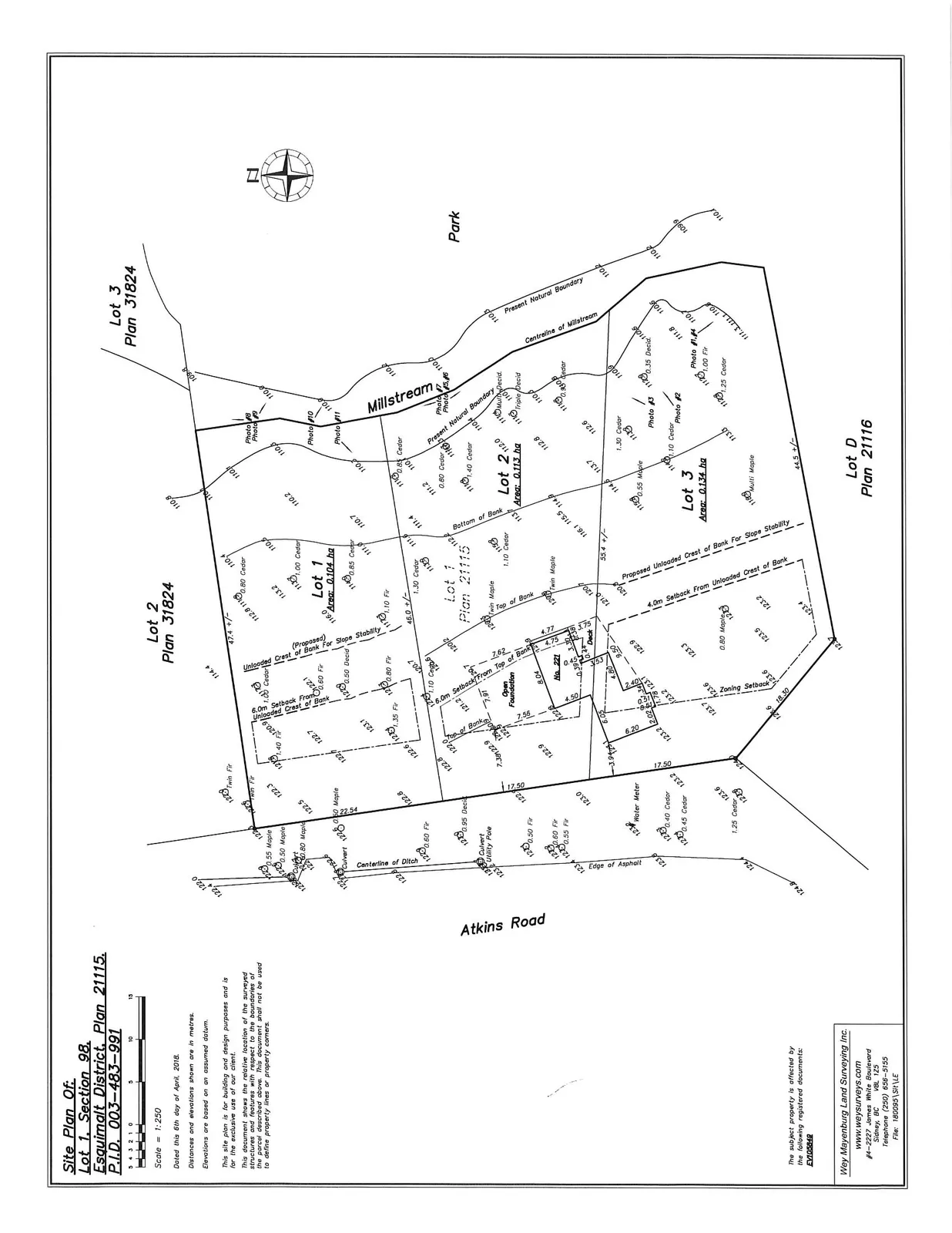
As requested, we have undertaken a lot specific slope stability analyses using computer modeling for each of the proposed lots. The following is intended to supplement our preliminary analysis as detailed in our Geotechnical Assessment Letter, which indicated a general setback from any slope crest of 7.5 m.
Our analysis applied a design seismic event with 2% probability of exceedance in 50 years. Slope contour information was based on the Layout Plan prepared by Wey Mayenburg Land Surveying Inc, attached. Our model was generated in accordance with Section 4.1.3, Factor of Safety and/or Slope Displacement, of the Guidelines for Legislated Landslide Assessments for Proposed Residential Developments in BC. Two-dimensional limit equilibrium analyses was utilized to identify potential failure surfaces and Newmark analyses was utilized to determine slope displacements during seismic ground motions. For Newmark analyses, a magnitude 9.0 seismic event originating from the Cascadia Subduction Zone was used and scaled to a Seismic Site Classification of 'C'.
Lot 1
A reduction to the general setback is possible provided the slope crest is unloaded. We recommend unloading the slope crest by incorporating a walk-out basement level to any proposed development. Our model considered a walk-out basement level would lower site grades near the crest by approximately 3.5 m which, in turn, provides an addition 4.5 m horizontal distance relative to the existing crest location. Based the analysis, we consider a safe setback for residential foundations from the lowered crest to be 6.0 m. Results from the Newmark analysis indicate that ground displacement would not exceed 2.6 cm beyond a 6.0 m setback, which is well below the maximum tolerable slope displacement of 15 cm in accordance with the legislative guidelines.
Lot 2
The proposed Lot 2 includes the existing residence/open foundation, as indicated on the attached Survey and Proposed Subdivision Plan. We recommend that a walk-out basement level is maintained for this lot. The existing building setback from the crest is approximately 4.5 m. Based on our analysis, a minimum setback of 6.0 m should be maintained for any new residential development. Results from the Newmark analysis indicate that ground displacement would not exceed 0.2 cm within the 6.0 m setback line.
Lot 3
We consider a safe setback for residential foundations to be 5.0 m provided the residence is constructed roughly at the existing grade of the lot. This setback could be further reduced provided the slope crest is unloaded by 3.5 m. Based on our analysis, we consider a safe setback for residential foundations from the lowered crest to be 4.0 m. Results from the Newmark analysis indicated that ground displacement would not exceed 15 cm within 5.0 m of the slope crest provided existing grade is maintained.
Closure
In general, we consider that unloading the slope crest and constructing the residential buildings behind the provided setbacks would improve slope stability on the site. The following table summarizes the minimum setback for residential foundations from the crest of the predominant slope based on our stability analysis.
Table 1: Summary of Setbacks
| Proposed Lot | Minimum Setback for Residential Foundations |
|---|---|
| 1 | 6.0 m from the lowered crest |
| 2 | 6.0 m from the lowered crest |
| 3 | 5.0 m from the existing crest |
| 3 | 4.0 m from the lowered crest |
Minimal disturbance of vegetation should occur within the area between the slope crest and the proposed residences. Areas subject to excavation/unloading along the slope crest should be excavated with care and re-vegetated as soon as possible. Landscaping features should be constructed such that surface flows are not concentrated to discharge at the slope crest. Alternatively, collected water could be conveyed downslope via secured solid pipe network and discharged onto non-erodible soils.
We trust that the above is suitable for your purposes at present. Please don't hesitate to contact our office if you have any questions.
Sincerely, Ryzuk Geotechnical
Colden Van Ommen, EIT Junior Engineer
Andrew Jackson, P.Geo., Eng.L. Geoscientist / Engineering Licensee
Attachments - Layout Plan prepared by Wey Mayenburg
Document Images
(3)