Appendix
Attachment 4: Sign Plans and Structural Drawings
November 8, 2022Pages 246–2505 sections
Technical design specifications and engineering drawings for the proposed digital menu boards and order confirmation units.
October 26, 2021Drawing BK_-PS116x0084.125BLoads calculated per BCBC 2018
Order Confirmation Unit
Scale: 3/8"=1'-0"
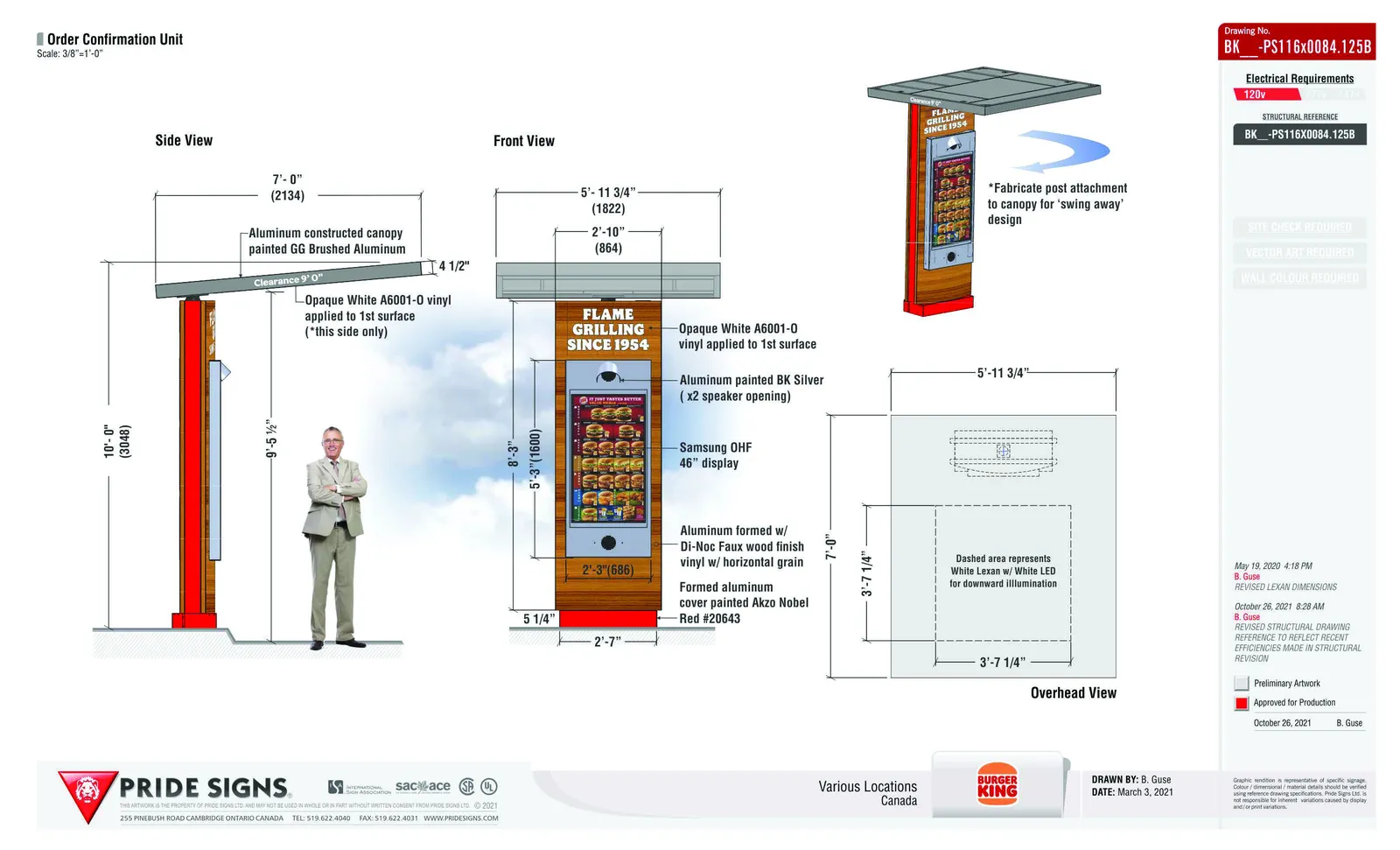
Side View Callouts
- 7'- 0" (2134) canopy depth
- Aluminum constructed canopy painted GG Brushed Aluminum
- Clearance 9' 0"
- Opaque White A6001-O vinyl applied to 1st surface (*this side only)
- 4 1/2" canopy thickness
- 9'-5 1/2" height to top of front canopy edge
- 10'- 0" (3048) total unit height
Front View Callouts
- 5'- 11 3/4" (1822) total canopy width
- 2'-10" (864) width of main unit upper section
- FLAME GRILLING SINCE 1954 text
- Opaque White A6001-O vinyl applied to 1st surface
- Aluminum painted BK Silver (x2 speaker opening)
- Samsung OHF 46" display
- Aluminum formed w/ Di-Noc Faux wood finish vinyl w/ horizontal grain
- 2'-3" (686) display width
- Formed aluminum cover painted Akzo Nobel Red #20643
- 5 1/4" base detail height
- 2'-7" base width
- 8'-3" total unit height
- 5'-3" (1600) display unit body height
Isometric View Note
- *Fabricate post attachment to canopy for 'swing away' design
Overhead View Callouts
- 5'-11 3/4" canopy width
- 7'-0" total depth
- 3'-7 1/4" unit width
- Dashed area represents White Lexan w/ White LED for downward illumination
- 3'-7 1/4" unit depth
Drawing Information
- Drawing No.: BK __-PS116x0084.125B
- Electrical Requirements: 120V
- Structural Reference: BK __-PS116x0084.125B
- Locations: Various Locations Canada
- Date: March 3, 2021
- Drawn By: B. Guse
- Revisions:
- May 19, 2020: REVISED LEXAN DIMENSIONS (B. Guse)
- October 26, 2021: REVISED STRUCTURAL DRAWING REFERENCE TO REFLECT RECENT EFFICIENCIES MADE IN STRUCTURAL REVISION (B. Guse)
Page 246–250
Projecting Drive Thru Canopy
Location: 1681 OLD ISLAND HIGHWAY, VIEW ROYAL, VICTORIA, BC Drawing No.: BK __-PS116x0084.125B Sheet: 1 OF 2
[Diagram: Side and front elevation structural drawings of the OCU canopy and support post]
Structural Notes and Dimensions
- 7" x 7" x 1/2" STEEL MATCH PLATE w/ Ø 3 1/2" SCH40 STEEL PIPE STUB SECURED TO CANOPY w/ Ø 1/2" x 1 1/2" HEX BOLTS - (4) PL., Ø 3" SCH80 STEEL PIPE STUB SLEEVED INTO POST w/ Ø 3/4" PINCH BOLTS
- 7'-0" canopy length
- 4 1/2" canopy height
- 9'-11 1/4" total height to top of canopy
- 8'-8 1/2" mid-post height mark
- 9'-3 15/16" height to bottom of canopy
- 5'-11 3/4" total canopy width
- 1'-9 1/2" offset from post center
- 2" x 4" x 1/8" STEEL TUBE CANOPY FRAME w/ ACM CLADDING
- LED DOWNWARD ILLUMINATION
- ALUMINUM SIGN BOX ATTACHED TO STEEL STRUCTURE w/ #10x1 1/2" C'SUNK TEK SCREW - (x10) PL.
- REMOVABLE BACK PANEL ATTACHED w/ #10x1 1/2" C'SUNK TEK SCREW - (x4) PL.
- SPEAKER w/ DOME COVER
- MICROPHONE
- 4" x 4" x 1/4" HSS WELDED TO TOP OF STEEL BASE PLATE
- Weld Symbols: 1/4" TYP., 1/4" 3 PASSES
- 2'-10 1/8" width of main unit body
- 2'-7" base width
- 5'-3" total display unit height
- 4'-4 1/2" display unit body height
- 1'-2 3/4" bottom of unit height from base
- 5 1/4" base height
Design Notes
- LOADS AS PER B.C.B.C 2018 FOR VIEW ROYAL, VICTORIA, BC AREA:
- WIND q(1/50) = 0.57 KPa
- SNOW Ss = 1.1 KPa, Sr = 0.2 KPa
- GENERAL WELD NOTE: 1/8" FILLET WELD REQ'D UNLESS OTHERWISE NOTED
Project Details
- Drawn By: C. LENZ, 25-Oct-21
- Checked By: C. LENZ, 25 Oct 21
- Total Amp Draw: 6.3 A @ 120 V
Page 246–250
Projecting Drive Thru Canopy - Foundation Details
Location: 1681 OLD ISLAND HIGHWAY, VIEW ROYAL, VICTORIA, BC Drawing No.: BK __-PS116x0084.125B Sheet: 2 OF 2
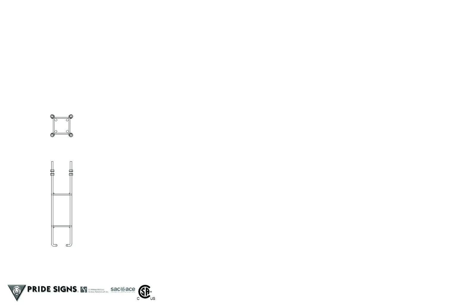
Parts List
| # | PART | QTY | DESCRIPTION | WIDTH | LENGTH |
|---|---|---|---|---|---|
| 1 | AB005 | 4 | Ø3/4" ANCHOR BOLT | 3'-0" | |
| 2 | PAT308 | 1 | 3/4" PLYWOOD PATTERN - Ø3/4"-8"x8" | 11" | 11" |
Concrete Caisson Foundation Notes
- 15M REBAR VERTICALS EQUALLY SPACED
- 10M REBAR CIRCULAR TIES WITH 9" LAP
- 3/4" DIA. ANCHOR BOLTS (ASTM A307)
- 1 1/2" DIA. ELECTRICAL CONDUIT IN CONCRETE BASE
- 2'-0" Diameter caisson
- (6) 15M VERTICAL REBAR
- (11) 10M REBAR CIRCULAR TIES
- 8'-0" total depth
- 6" from grade to top of concrete
- 3" CLEARANCE at bottom
- CONDUIT MIN 18" BELOW GRADE
- DMB - (x4) 1" CONDUITS: x2 - POWER, x1 - DATA, x1 - SPEAKER / MICROPHONE (IF REQUIRED)
Design Notes
- DESIGN LOADS AS PER BCBC 2018 FOR VICTORIA, BC: q 1/50 = 0.57 KPa, Ss = 1.1 KPa, Sr = 0.2 KPa
- PRESUMPTIVE ALLOWABLE SOIL BEARING CAPACITY: 2000 psf.
- PRESUMPTIVE ALLOWABLE PASSIVE LATERAL SOIL RESISTANCE: 150 psf/ft.
Specifications
- HSS SECTIONS SHALL CONFORM TO CSA G40.21M-350W.
- STEEL PLATES SHALL CONFORM TO CSA G40.21M-300W.
- REINFORCING STEEL SHALL CONFORM TO CSA G30.18-09 GRADE 400.
- ANCHOR BOLTS TO BE MANUFACTURED FROM ASTM A-36 (A307) BAR OR GREATER.
- CONCRETE SHALL HAVE A MINIMUM COMPRESSIVE STRENGTH AFTER 28 DAYS OF 25 MPa.
- CONCRETE SHALL HAVE 4” - 5” SLUMP WITH 4% - 7% AIR ENTRAINMENT, VIBRATE DURING PLACEMENT.
- ALL CONCRETE WORK TO BE IN CONFORMANCE WITH CSA-A23.1.
- CONCRETE MUST BE POURED AGAINST UNDISTURBED SOIL, NO BACKFILL AROUND FOUNDATION.
- IF BACKFILL IS REQUIRED, IT IS TO BE PLACED IN SUITABLY COMPACTED LAYERS (DEPTHS SELECTED IN ACCORDANCE WITH THE EQUIPMENT USED), WITH EACH LAYER COMPACTED TO 95% MODIFIED PROCTOR DENSITY.
- CONCRETE REQUIRES A MIN. OF 7 DAYS OF CURE TIME PRIOR TO INSTALLATION OF SIGN.
- CONNECTION BOLTS FOR SIGN BOXES SHALL CONFORM TO SAE J429 GRADE 5 OR GREATER.
Page 246–250
S/S Digital Menu Board
Scale: 1/2" = 1'-0"
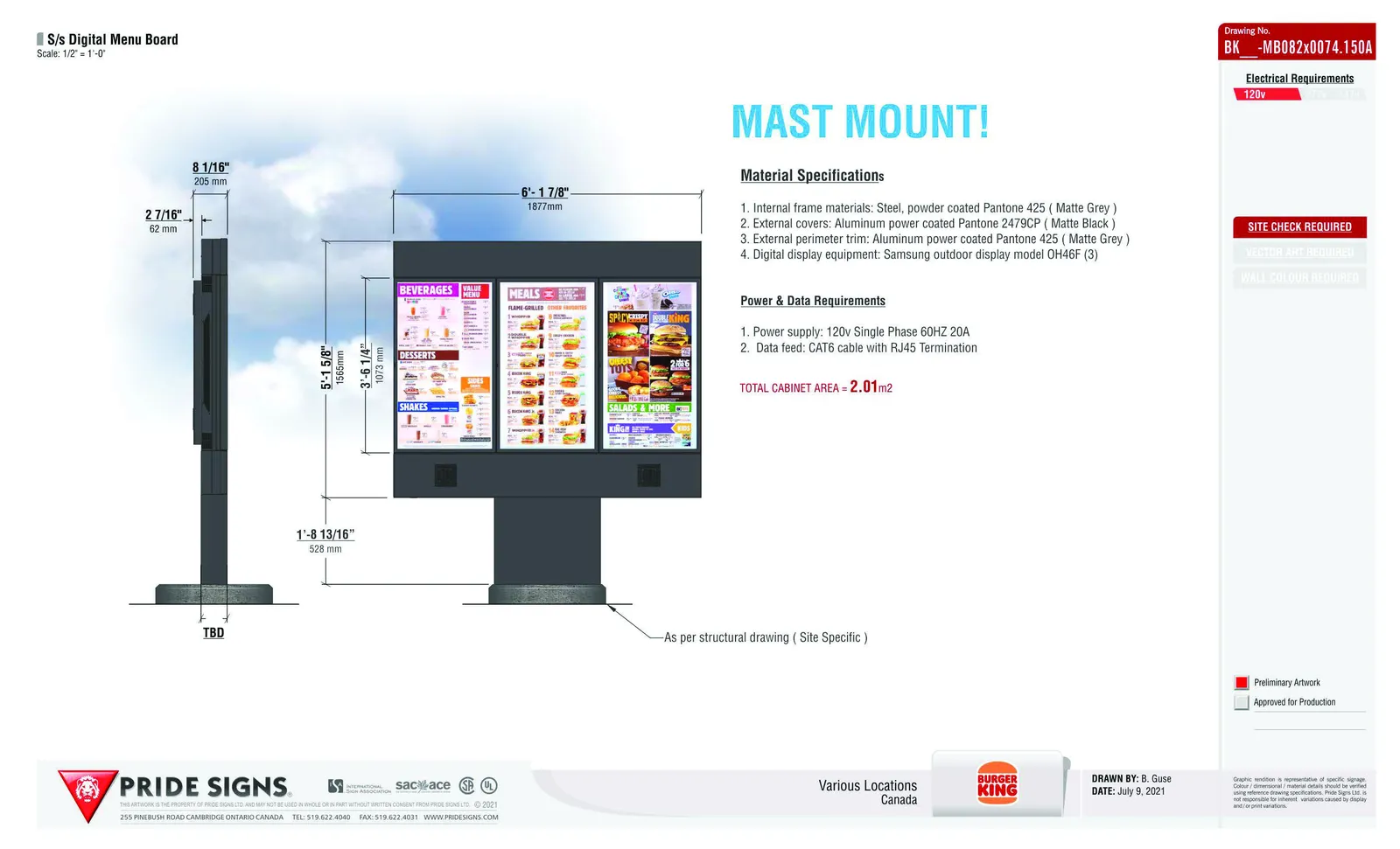
Dimensions and Features
- 2 7/16" (62 mm) display depth
- 8 1/16" (205 mm) pedestal depth
- 6'- 1 7/8" (1877 mm) total display width
- 5'-1 5/8" (1565 mm) display cabinet height
- 3'-6 1/4" (1073 mm) visible display area height
- 1'-8 13/16" (528 mm) pedestal width
- Note: -As per structural drawing ( Site Specific )
- Total Cabinet Area: 2.01 m2
Material Specifications
- Internal frame materials: Steel, powder coated Pantone 425 ( Matte Grey )
- External covers: Aluminum power coated Pantone 2479CP ( Matte Black )
- External perimeter trim: Aluminum power coated Pantone 425 ( Matte Grey )
- Digital display equipment: Samsung outdoor display model OH46F (3)
Power & Data Requirements
- Power supply: 120v Single Phase 60HZ 20A
- Data feed: CAT6 cable with RJ45 Termination
Drawing Information
- Drawing No.: BK __-MB082x0074.150A
- Electrical Requirements: 120V
- Drawn By: B. Guse
- Date: July 9, 2021
Page 246–250
ODMB, 46" Triple Pedestal Menu Display
Location: 1681 OLD ISLAND HIGHWAY, VIEW ROYAL, VICTORIA, BC Drawing No.: BK __-MB013574.150A1 Sheet: 1 OF 1
[Diagram: Structural elevation and footing details for the triple pedestal menu display]
Parts List
| # | PART | QTY | DESCRIPTION | LENGTH |
|---|---|---|---|---|
| 1 | BOLT146 | 4 | 3/4" x10" WEDGE BOLT | |
| 2 | NUT011 | 12 | 3/4" STEEL HEX NUT - GRADE 5 | |
| 3 | WASH047 | 12 | Ø3/4" STEEL WASHER | |
| 4 | PLY002 | 1 | ROUTED PLYWOOD PATTERN ITEM #4 NOT SHOWN | 1'-8" |
General Notes
- EXISTING MENU BOARD AREA = 67 SF
- NEW MENU BOARD AREA = 35.5 SF
- PROPOSED MENU BOARD HAS SIGNIFICANTLY LESS WIND LOAD THAN EXISTING MENU BOARD
- BOLTS MUST BE TRIMMED TO FIT INSIDE OF BASE COVER
Wedge Bolt Installation Procedure
- CUT ANY EXISTING BOLTS FLUSH TO GRADE
- DRILL Ø3/4" HOLE - 7" INTO EXISTING CONCRETE USING PLYWOOD PATTERN PROVIDED
- BLOW OUT HOLE / CLEAN HOLE
- PLACE WEDGE BOLTS INTO DRILLED HOLES
- PLACE WASHER AND NUT
- TIGHTEN INTO PLACE - MIN 4" ABOVE GRADE
- MINIMUM EMBEDMENT OF 5.625" BELOW TOP OF BASE
Design Notes
- LOADS AS PER BCBC - 2018 FOR VIEW ROYAL, VICTORIA, AREA:
- WIND q(1/50) = 0.57 kPa
- SNOW Ss = 1.1 kPa, Sr = 0.2 kPa
Drawing Details
- Drawn By: A. SARIN, 27-Sep-22
- Released for Permit: A. SARIN, 28-Sep-22
- Weight: 629 LBS
Page 246–250
Document Images
(1)
Extracted from: 2022 11 08 Committee of the Whole Agenda - Agenda - Pdf