Attachment 6: 2022 11 29 - (buepoint) Framing review
Detailed framing review report including instructions and marked-up plans.
Framing Review
Project Address: 12 Vickery Road., Victoria, BC Project No.: 10441 Contact: John Becker Date/Time: 2022.11.29 2:00PM Type of Review: Framing
Observations
- some shearwalls missing blocking at plywood joints
- nails missing in shearwalls
- holddowns missing in upper exterior shearwalls, straps installed in place of holddowns
- shearwall bottom plates nailed to each floor joist, shearwall sheathing laps with rimboard
- clerestory shearwall missing uplift anchorage, received no photos of clerestory shearwall nailing
- several instructions from previous framing review still need to be addressed
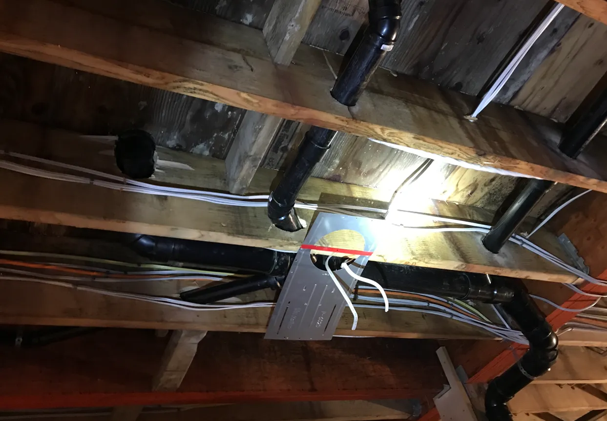
- large penetration compromises floor joist under bathroom
- strap not installed between LVL beam and sill plate at keynote 23 location
- back bedroom roof framing has rafters bearing on single ply 2x12 ridge beam with insufficient support
- entry exterior wall framing is discontinuous with mid plate interrupting studs
- existing entry ridge does not extend to B3 LVL beam
- cracked joist at cant. front deck backspan
- straps not installed at keynote 20 and 24 locations
- floor joists aligned with shearwall between GL-B and -C, but straps not installed between joists per keynote 15
Framing Checklist
| Item | Reviewed | Incomplete | N/A |
|---|---|---|---|
| Conformance with truss spec: | X | ||
| Conformance with I-joist drawings: | X | ||
| Beam and girder bearing: | X | ||
| Continuity of top plates: | X | ||
| Lintels/openings: | X | ||
| Shearwalls/Fastening/Hold-downs: | X | ||
| Continuity of tall walls: | X | ||
| Floor system blocking for point loads: | X | ||
| Wall sheathing: | X | ||
| Wind girts: | X | ||
| Post to beam free standing: | X | ||
| Fasteners in hardware: | X | ||
| Shearwalls to floor system: | X | ||
| Penetrations: | X | ||
| LLRS consistent: | X |
Comments
- mechanical penetrations to be reviewed at a later date
- follow-up framing review will be necessary
- strapping shearwall ends to rimboard is not sufficient to resist uplift, holddowns into the foundation are required
Instructions: see following pages for instructions and sketches
Status: Further Review Required
Reviewed by: Trevor Kinnee, EIT
Instructions (from 2022.11.21 review slip)
provide photos of exterior shearwall sheathing nailing w/ measuring tape in frameinstall holddowns and straps (as applicable) at shearwall ends where missingprovide blocking and nailing at all shearwall panel jointsextend exterior wall sheathing to lap over top plate, block and nail sheathing panel joints (6" o/c for regular walls and 3" o/c for shearwalls)provide horizontal straps connecting framing members per plan (see keynotes 14, 15, 20, and 24)provide photos of shearwall bottom plate fastening for review-> Note: bottom plates nailed to each joist, shearwall sheathing laps with rim boardprovide nails between shearwall end studs and posts per keynote 10provide (2) 3/8" x 7-1/4" GRK RSS @ 12" o/c through 5-ply built-up D.Fir posts (alternating faces)-> reviewed 2022.11.29for rafters supporting outlook joists, provide full-depth blocking @ 48" o/c against adjacent rafters. where outlook joist backspans are hung from SPF rafters, double-up rafter.-> blocking installed, SPF rafters OK- where LVL beams have ply joints at midspan, sister an additional continuous LVL ply to match the number of continuous plies noted in the beam schedule -> straps installed instead of GRK's, OK (2023.01.23 photos)
provide min. (2) 3/8" GRK's between LVL beams and 5-ply built-up posts- cut continuous LVL beams at supports, ensure adequate bearing is maintained
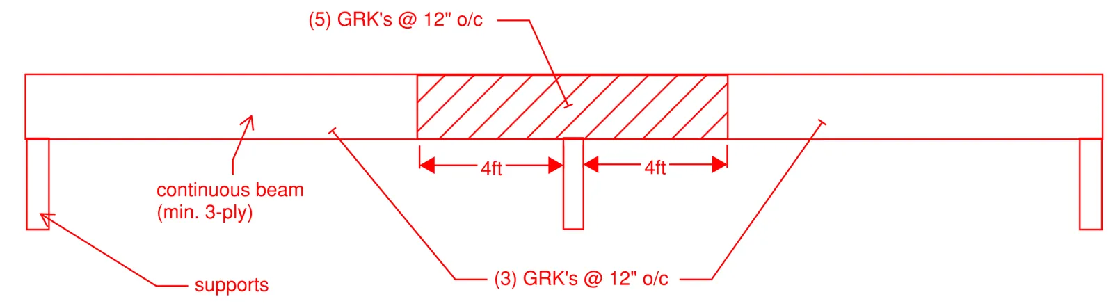
- for continuous beams where plans note separate spans, add a continuous ply and provide (5) GRK's @ 12" o/c within 4ft of midspan supports, provide (3) GRK's 12" o/c elsewhere
provide blocking between rafters above exterior walls-> could do blocking to adjacent rafter as alternative- install LSL drag strut alongside master bedroom shearwall per keynote 22 on plans
replace post plies that have joints at mid height, all post plies must be continuous- provide blocking between GL-2 shearwall studs past GL-A and install MSTC28 strap between added blocking and lower LVL beam end at GL-A -> strap incorrectly installed vertically in 2023.01.23 photos
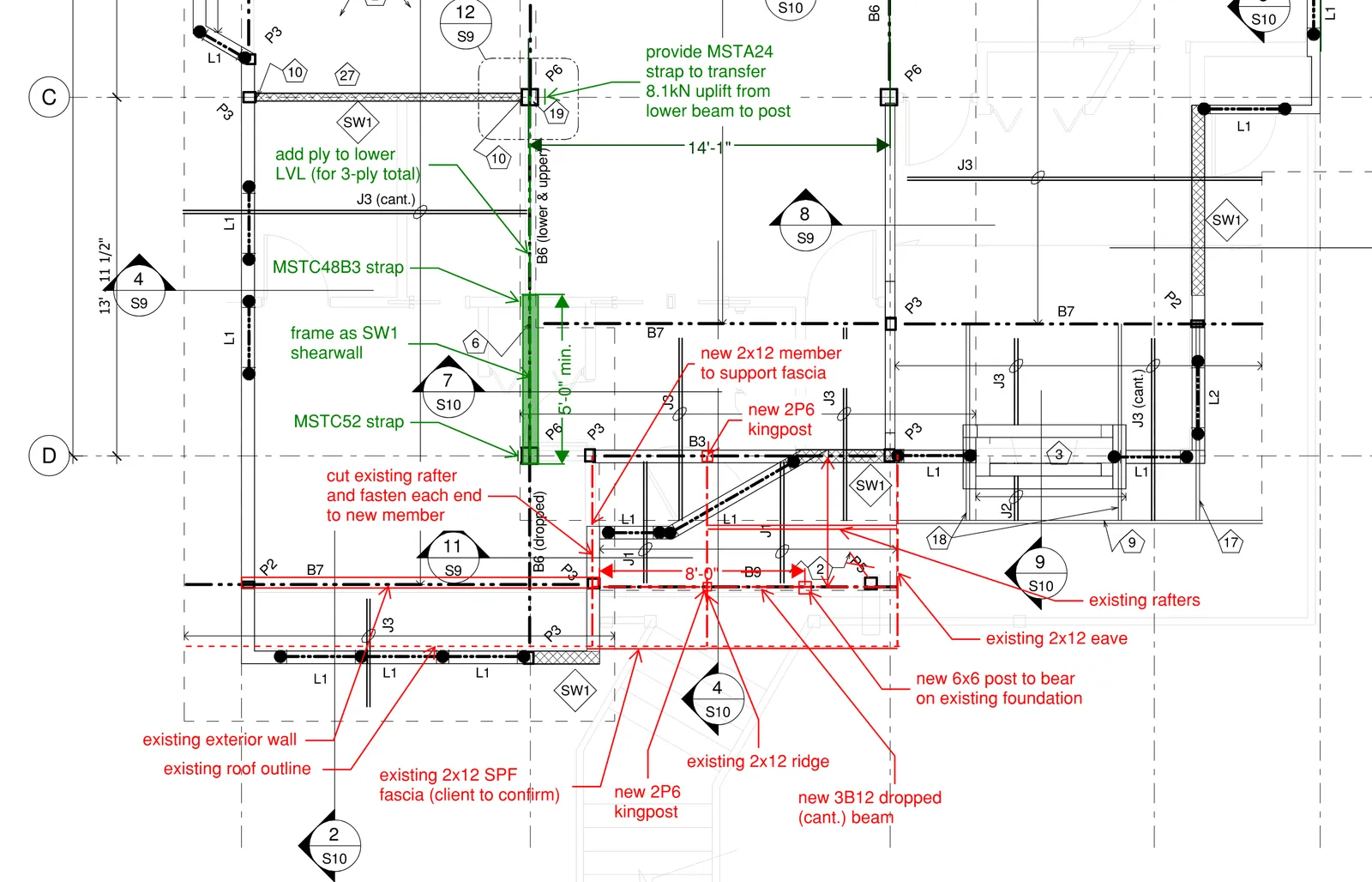
- provide entry roof structure as marked up in detail (see below) -> some framing appears to be done from photos
- add ply to GL-2 lower roof beam between GL-C and -D (see markups below)
- provide MSTA24 strap between beam and post at GL-2C -> photos received 2023.01.23
- frame clerestory wall as SW1 shearwall between GL-D and nearest opening (min. 5'-0" length)
- provide MSTC52 strap at GL-D end of clerestory shearwall between shearwall end post and post below
- provide MSTC48B3 pre-bent strap between clerestory shearwall end post and beam below at mid span
Instructions (from latest framing review)
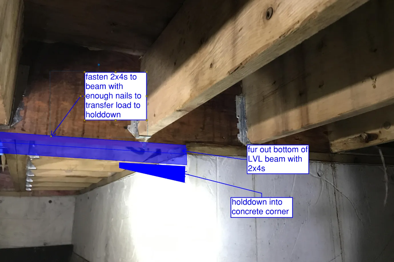
- at GL-2A, scab (2) 2x4's onto bottom edge of LVL beam c/w min. (32) 3-1/2" nails each, install HTT5 holddown onto scabbed 2x4s, drill and epoxy 5/8" rod min. 8" into concrete, see sketch below
- along sections of continuous beams that remain as two-ply provide (5) GRK's @ 8" o/c within 4ft of midspan supports (see sketch below)
provide min. 3-ply 2x6 SPF no. 1/2 dropped purlins to support rafters above back bedroom, support on LVL along GL-A w/ 3-ply 2x4 posts (see sketch below)-> photos received 2023.01.23nail SPF plate to top edge of GL-A LVL beam w/ 3" nails @ 4" o/c alternating between plies (see sketch below)
replace studs at exterior entry wall corners with 2-ply posts continuous from floor to ceiling, nail existing midplates to posts w/ min. (3) 3" toe-nails
provide min 2-ply 2x6 post in wall to support existing 2x12 ridge (see sketch below)
at either end of GL-4 LVL, scab 2x12 to face of beam w/ min. (8) 3" nails, extend scabbed 2x12 to nearest perpendicular rafter, provide blocking between adjacent rafter and install LSTA18 strap between scabbed 2x12 and rafter blocking, see sketch below (since keynotes 20 were not done on site)
at LVL above master bathroom door, install 2x12 on flat, ripped to suit, between wall top plate and adjacent rafter, provide 3" nails @ 6" o/c between 2x12 and top plate, and between new 2x12 and rafter (since keynote 24 was not done on site)
cut out plumbing at large penetration near GL-C (see photo below) and add two 2x12 SPF joists, one either side of where toilet line is going
where floor joists are aligned under shearwall between GL-B and GL-C, connect joists through GL-3 beam using an HTT5 c/w #10 x 1-1/2" SD screws either side and connecting together with 5/8" rod through mid-depth of beam, see sketch below (since keynote 15 was not done on site)
where floor joist laps with LVL beam under shearwall between GL-B and -C, provide (3) 3/8" x 4" GRK's @ 12" o/c between joist and LVL, see sketch below (since keynote 15 was not done on site)
sister 2x12 SPF ply to backspan of cracked front deck cantilever joist
Structural Framing Plan Details
GL-2A Area
- Callout #26: nail SPF plate to LVL beam w/ 3" nails @ 4" o/c alternating (plate installed but fastening unverified)
- Callout #25: min. 3-ply 2x6 dropped SPF purlin supported by min 3-ply 2x4 king posts bearing on LVL.
GL-2D Area
- Callout #28: provide min. 2-ply 2x6 post in wall to support ridge.
- Callout #27: replace discontinuous corner studs with continuous 2-ply 2x6 posts, toe-nail existing mid-plates to new posts w/ min. (3) 3" nails.
- Note: entry roof framing markups not shown for clarity, see 2022.11.21 review slip.
GL-3B+ and GL-4B+ Areas
- Callout #29: new 2x12 scabbed to end of B6; LSTA18 strap (bottom edge); new 2x12 rafter blocking.
GL-4B and GL-4C Area
- Callout #33: provide (3) 3/8" x 4" GRK's @ 12" o/c between joist and LVL beam.
- Callout #32: provide HTT5's to joists c/w #10 x 1-1/2" SD screws connected w/ 5/8" rod through mid-depth of beam.
- Other markups: "install holddown", "install straps between shearwall above and beam below".
General Plan Notes
- Callouts for #10 and #12 across various beams: "appears to be installed from 2023.01.23 photos, cannot verify GRK installation per instruction 12".
- "22' new ply" noted at multiple beam locations.
- Callout #24: "will need (5) GRK's @ 8" o/c here since this section will be 2-ply".
Document Images
(3)