Appendix
Attachment 7: 2023 03 14 - (buepoint) Follow up Framing review
November 19, 2024Pages 55–596 sections
Follow-up review highlighting that several framing issues remained unaddressed.
Date: 2023.03.14Finding: Further review required
Attachment 7: 2023 03 14 (Buepoint) Follow up Framing review
Page 55–59
Project Details
- Project Address: 12 Vickery Road., Victoria, BC [Image 15]
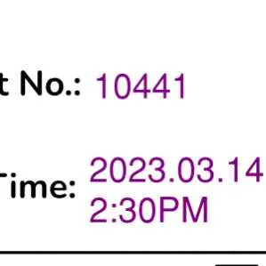
- Project No.: 10441 [Image 36]
- Contact: John Becker
- Date/Time: 2023.03.14 2:30PM [Image 37]
- Type of Review: [x] Framing [Image 16]
Page 55–59
Observations
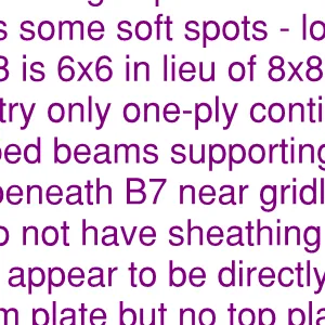
- ceiling framing at entry will offer some lateral support to front wall
- floor is not level, has high spots and low spots - structurally not a concern
- feels like floor has some soft spots - looks like floor sheathing is discontinuous between joists
- post at gridline C3 is 6x6 in lieu of 8x8 per plans - OK
- B3 beam near entry only one-ply continuous, 11-7/8" deep, spans about 8ft rather than 3ply 9-1/4" per plans - OK
- none of the dropped beams supporting the front deck are continuous, multiple ply joints
- P2 post missing beneath B7 near gridline D
- some walls still do not have sheathing continuous to top plate
- front deck beams appear to be directly in contact with concrete
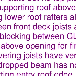
- lintels have bottom plate but no top plate per drawings
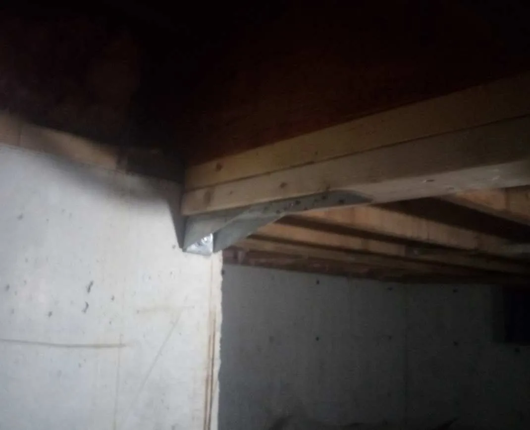
- dropped purlins supporting roof above backroom not given proper bearing or hangers in exterior wall
- no rimboard along lower roof rafters along GL-2 per detail 2/S9
- no blocking between front deck joists above bearing locations
- no perpendicular blocking between GL-A beam and adjacent joist per detail 1/S9
- no lintel provided above opening for fireplace near GL-D
- front deck cantilevering joists have very little backspan
- 12'-9" front deck dropped beam has no continuous plies
- single 2x6 supporting entry roof edge
- horizontal holddown installed at GL-2A, could not verify fastening of scabbed material
- roof sheathing not continuous at back roof corner, fascia not continuous along edge
Page 55–59
Framing Review Checklist [Image 31]
| Framing Item | Reviewed | Incomplete | N/A | Comments [Image 44] |
|---|---|---|---|---|
| Conformance with truss spec: | [x] | concrete topping for leveling the floor should NOT be used as the floor framing was not designed for the additional weight [Image 45] | ||
| Conformance with I-joist drawings: | [x] | |||
| Beam and girder bearing: | [x] | |||
| Continuity of top plates: | [x] | finishes may deform resulting from settlement of as-built framing as there are several places where the framing doesn't fit well or is shimmed or blocked or on multiple plies of horizontal framing [Image 47] | ||
| Lintels/openings: | [x] | |||
| Shearwalls/Fastening/Hold-downs: | [x] | |||
| Continuity of tall walls: | [x] | |||
| Floor system blocking for point loads: | [x] | |||
| Wall sheathing: | [x] | |||
| Wind girts: | [x] | |||
| Post to beam free standing: | [x] | |||
| Fasteners in hardware: | [x] | |||
| Shearwalls to floor system: | [x] | |||
| Penetrations: | [x] | |||
| LLRS consistent: | [x] |
Page 55–59
Instructions
see following pages for instructions and sketches [Image 4]
[x] Further Review Required [Image 5]
Reviewed by: Mark Buesink, P.Eng
Page 55–59
Instructions:
- provide confirmation of holddowns and straps (as applicable) at shearwall ends where missing
- extend wall sheathing to lap over top plate, block and nail sheathing panel joints (6" o/c for regular walls and 3" o/c for shearwalls)
- removed
- provide nails between shearwall end studs and posts at keynote 10 location on gridline 4 (see markup next page)
- for continuous dropped roof beams along gridlines 2 and 3, provide (5) GRK's @ 12" o/c within 4ft of midspan supports, provide (3) GRK's 12" o/c elsewhere
- nail sheathing for master bedroom shearwall to top plate and LVL rimjoist above per shearwall schedule
- sheath inside face of clerestory wall between GL-D and nearest opening as SW1 shearwall (min. 5'-0" length), see markup on following page
- provide MSTC48B3 pre-bent strap between clerestory shearwall end post and beam below at mid span
- along sections of continuous beams that remain as two-ply provide (5) GRK's @ 8" o/c near within 4ft of midspan supports (see sketch below)
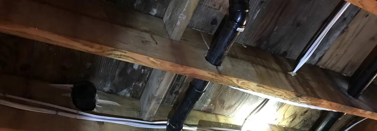
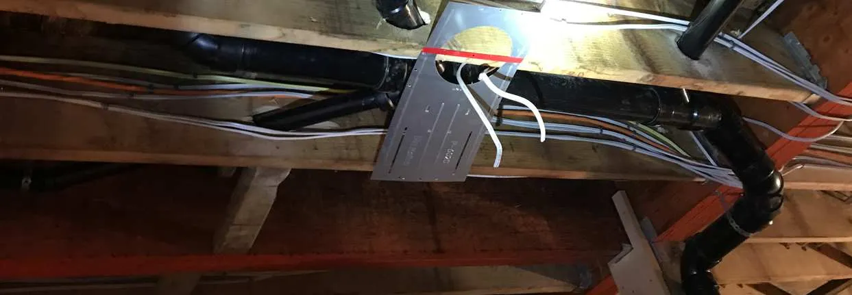
- pack out joist at large toilet penetration near GL-C (see photo following) and add two 2x6 SPF joists, one either side of where toilet line is going spanning minimum 3' past penetration on each side.
- where floor joist laps with LVL beam under shearwall between GL-B and -C, provide (5) 3" nails @ 6" o/c between joist and LVL, see markup below (since keynote 15 was not done)
- sister 2x12 SPF ply to backspan of cracked front deck cantilever joist (near GL-2)
- sister an additional 2x6 ply to the 2x6 supporting the entry roof edge (for two plies total, see sketch following)
- client to confirm nailing used at GL-2A to scab 2x4's to bottom edge of LVL beam to connect horizontal holddown
- provide 2-ply 2x6 post near GL-4 and D to support B7 beam as noted on plans
- nail sheathing to beam above GL-2 shearwall near GL-A per shearwall schedule
- removed
- confirm that A35's installed between GL-C shearwall top plate and roof joist per keynote 27 (comment on original framing review slip requested this to be confirmed)
- provide min. 2x6 lintel above fireplace opening
- provide continuous structural fascia between roof corner and ridge along back roof overhang since roof sheathing is not continuous
- client to confirm A35's have been installed between roof rafter blocking and shearwall top plates per detail 6/S9
- provide blocking between lower roof rafters along GL-2 in lieu of rimboard per detail 2/S9
- add studs either side of exterior wall posts supporting dropped purlins in back room, provide beam hangers to support purlins
- provide new joists to support cantilevered front deck c/w full backspan to gridline D wall, sister to existing joists (see markup below)
- replace long-span front deck beam with 4-ply SPF no. 1/2 or 8x8 D.fir per plan
- provide perpendicular joist blocking between GL-A beam and adjacent joist per detail 1/S9
provide photos of the above works completed
GRK Fastening Detail for Continuous Beams
[Image of diagram illustrating GRK fastener placement on multi-ply beams]
- #9: At 2-ply sections, (5) GRK's @ 8" o/c near midspan supports for 4ft.
- #5: (5) GRK's @ 12" o/c within 4ft of midspan supports.
- #5: (3) GRK's @ 12" o/c elsewhere on continuous beam (min. 3-ply).
Framing Plan Sketches
Upper Floor Framing - North Section [Image of plan showing GL-4, GL-B, and GL-C]
- #11 Callout: "provide (5) 3" nails @ 6" o/c o/c between joist and LVL beam" at intersection near GL-B.
- #4 & #6 Callouts: Near GL-4.
Lower Level/Deck Framing - South Section [Image of plan showing GL-D, entry area, and front deck]
- #8 Callout: MSTC48B3 strap location.
- #7 Callout: Shearwall SW1.
- #19 Callout: Fireplace lintel location.
- #15 Callout: Support post for B7.
- #13 Callout: 2-ply 2x6 SPF no. 1/2 entry roof support.
- Other callouts for 2x12 ridge, 6x6 kingpost, and 3B12 dropped cant. beams.
- #25 Callout: Replacement of front deck beam.
Construction Photos and Fascia/Purlin Markups
Toilet Penetration Detail
GL-2A Connection Confirmation
Roof Overhang and Purlin Support Detail [Image of framing section drawing]
- #20 Callout: continuous 2x12 SPF no. 1/2 structural fascia required along back roof overhang.
- #23 Callout: add studs either side of exterior wall posts at GL-1.
Front Deck Cantilever and Beam Detail
[Image of deck framing plan section]
- #24 Callout: sister new cantilevered joists with full back span to gridline D wall, sistering to existing joists (J1 cant.).
- #25 Callout: replace front deck beam (B1 cant.) with 4-ply 2x8 SPF no. 1/2 or 8x8 D.fir no. 1.
- Diagram shows outline of deck above relative to LG1 beam and GL-B/GL-C.
Page 55–59
Document Images
(77)























Extracted from: 2024 11 19 Council Agenda - Agenda - Pdf