TECHNICAL DESIGN BRIEF - 9 ERSKINE LANE VIEW ROYAL, BC MULTI FAMILY RESIDENTIAL DEVELOPMENT
A comprehensive engineering design brief for the proposed multi-family residential development, covering servicing, water, sewer, and stormwater management.
TECHNICAL DESIGN BRIEF
9 ERSKINE LANE
VIEW ROYAL, BC
MULTI FAMILY RESIDENTIAL DEVELOPMENT
Prepared For: Town of View Royal 45 View Royal Avenue Victoria, BC V9B 1A6
ATTN: Michele Gill, ASCT
Prepared By: Islander Engineering Ltd. 623 Discovery St. Victoria, BC V8T 5G4
Date: October 9, 2019 Project: #2253
TABLE OF CONTENTS
1 INTRODUCTION ................................................................................................................................3 2 SERVICING ........................................................................................................................................3 2.1 Water Servicing (Domestic).......................................................................................................3 2.2 Fire Flow Capacity (Fire Underwriters Survey) ......................................................................3 2.3 Sanitary Sewer Servicing............................................................................................................4 2.4 Rain Water Management Calculations.....................................................................................7 2.4(a) Town of View Royal Rain Water Management Criteria ................................................7 2.4(b) Design Storm.........................................................................................................................8 2.5 Storm Water Management – Onsite.......................................................................................9 2.6 Storm Water Management – Offsite .................................................................................... 11 2.7 Hydro/Tel/Cable/Gas ............................................................................................................. 11 2.8 Transportation, Road Access and Egress..............................................................................12 3 CLOSURE........................................................................................................................................12
APPENDIX
A Site Plan - Figure 1 B Water Network - Figure 2 and FUS Calculations C Offsite Sanitary Sewer - Figure 3 and Sanitary Sewer Capacity Assessment D Stormwater Management - Figure 4
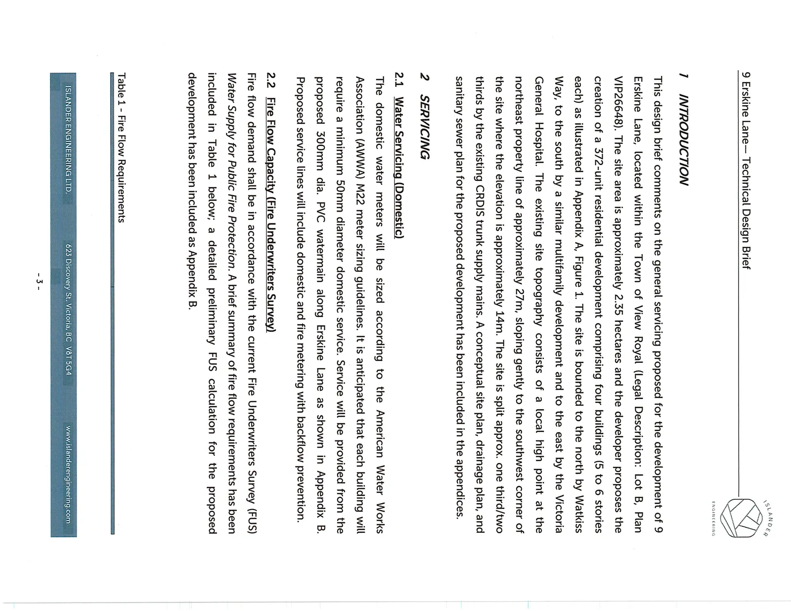
1 INTRODUCTION
This design brief comments on the general servicing proposed for the development of 9 Erskine Lane, located within the Town of View Royal (Legal Description: Lot B, Plan VIP26648). The site area is approximately 2.35 hectares and the developer proposes the creation of a 372-unit residential development comprising four buildings (5 to 6 stories each) as illustrated in Appendix A, Figure 1. The site is bounded to the north by Watkiss Way, to the south by a similar multifamily development and to the east by the Victoria General Hospital. The existing site topography consists of a local high point at the northeast property line of approximately 27m, sloping gently to the southwest corner of the site where the elevation is approximately 14m. The site is split approx. one third/two thirds by the existing CRDIS trunk supply mains. A conceptual site plan, drainage plan, and sanitary sewer plan for the proposed development has been included in the appendices.
2 SERVICING
2.1 Water Servicing (Domestic)
The domestic water meters will be sized according to the American Water Works Association (AWWA) M22 meter sizing guidelines. It is anticipated that each building will require a minimum 50mm diameter domestic service. Service will be provided from the proposed 300mm dia. PVC watermain along Erskine Lane as shown in Appendix B. Proposed service lines will include domestic and fire metering with backflow prevention.
2.2 Fire Flow Capacity (Fire Underwriters Survey)
Fire flow demand shall be in accordance with the current Fire Underwriters Survey (FUS) Water Supply for Public Fire Protection. A brief summary of fire flow requirements has been included in Table 1 below; a detailed preliminary FUS calculation for the proposed development has been included as Appendix B.
Table 1 - Fire Flow Requirements
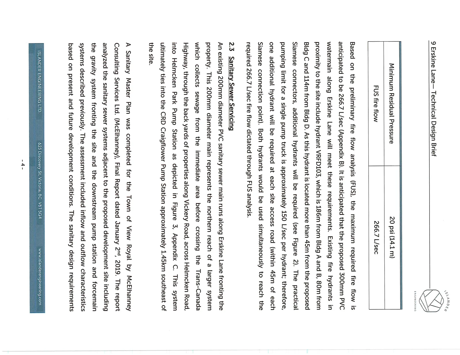
| Minimum Residual Pressure | 20 psi (14.1 m) |
| FUS fire flow | 266.7 L/sec |
Based on the preliminary fire flow analysis (FUS), the maximum required fire flow is anticipated to be 266.7 L/sec (Appendix B). It is anticipated that the proposed 300mm PVC watermain along Erskine Lane will meet these requirements. Existing fire hydrants in proximity to the site include hydrant VRFD103, which is 186m from Bldg A and B, 80m from Bldg C and 114m from Bldg D. As this hydrant is located more than 45m from the proposed Siamese connectors, additional hydrants will be required (see Figure 2). The practical pumping limit for a single pump truck is approximately 150 L/sec per hydrant; therefore, one additional hydrant will be required at each site access road (within 45m of each Siamese connection point). Both hydrants would be used simultaneously to reach the required 266.7 L/sec fire flow dictated through FUS analysis.
2.3 Sanitary Sewer Servicing
An existing 200mm diameter PVC sanitary sewer main runs along Erskine Lane fronting the property. This 200mm diameter main represents the northern reach of a larger system which collects sewage from the immediate area before crossing the Trans-Canada Highway, through the back yards of properties along Vickery Road, across Helmcken Road, into Helmcken Park Pump Station as depicted in Figure 3, Appendix C. This system ultimately ties into the CRD Craigflower Pump Station approximately 1.45km southeast of the site.
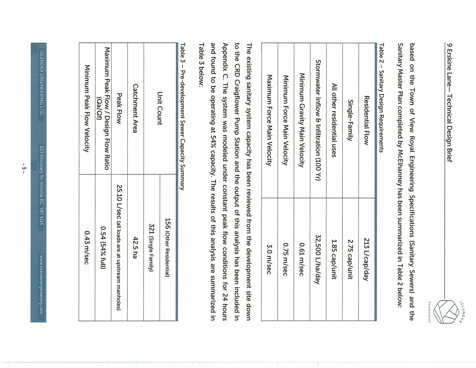
A Sanitary Master Plan was completed for the Town of View Royal by McElhanney Consulting Services Ltd. (McElhanney), Final Report dated January 2nd, 2019. The report analyzed the sanitary sewer systems adjacent to the proposed development site including the gravity system fronting the site and the downstream pump station and forcemain systems described previously. The assessment included inflow and outflow characteristics based on present and future development conditions. The sanitary design requirements based on the Town of View Royal Engineering Specifications (Sanitary Sewers) and the Sanitary Master Plan completed by McElhanney has been summarized in Table 2 below:
Table 2 – Sanitary Design Requirements
| Residential Flow | 213 L/cap/day |
| Single-Family | 2.75 cap/unit |
| All other residential uses | 1.85 cap/unit |
| Stormwater Inflow & Infiltration (100 Yr) | 32,500 L/ha/day |
| Minimum Gravity Main Velocity | 0.61 m/sec |
| Minimum Force Main Velocity | 0.75 m/sec |
| Maximum Force Main Velocity | 3.0 m/sec |
The existing sanitary system capacity has been reviewed from the development site down to the CRD Craigflower Pump Station and the output of this analysis has been included in Appendix C. The system was modeled under constant peak flow conditions for 24 hours and found to be operating at 54% capacity. The results of this analysis are summarized in Table 3 below:
Table 3 – Pre-development Sewer Capacity Summary
| Unit Count | 156 (Other Residential) |
| 321 (Single Family) | |
| Catchment Area | 42.5 ha |
| Peak Flow | 25.10 L/sec (all loads are at upstream manholes) |
| Maximum Peak Flow / Design Flow Ratio (Qa/Qf) | 0.54 (54% full) |
| Minimum Peak Flow Velocity | 0.43 m/sec |
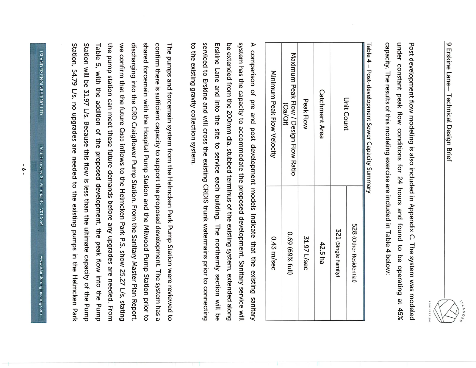
Post development flow modeling is also included in Appendix C. The system was modeled under constant peak flow conditions for 24 hours and found to be operating at 45% capacity. The results of this modeling exercise are included in Table 4 below:
Table 4 – Post-development Sewer Capacity Summary
| Unit Count | 528 (Other Residential) |
| 321 (Single Family) | |
| Catchment Area | 42.5 ha |
| Peak Flow | 31.97 L/sec |
| Maximum Peak Flow / Design Flow Ratio (Qa/Qf) | 0.69 (69% full) |
| Minimum Peak Flow Velocity | 0.43 m/sec |
A comparison of pre and post development models indicate that the existing sanitary system has the capacity to accommodate the proposed development. Sanitary service will be extended from the 200mm dia. stubbed terminus of the existing system, extended along Erskine Lane and into the site to service each building. The northernly section will be serviced to Erskine and will cross the existing CRDIS trunk watermains prior to connecting to the existing gravity collection system.
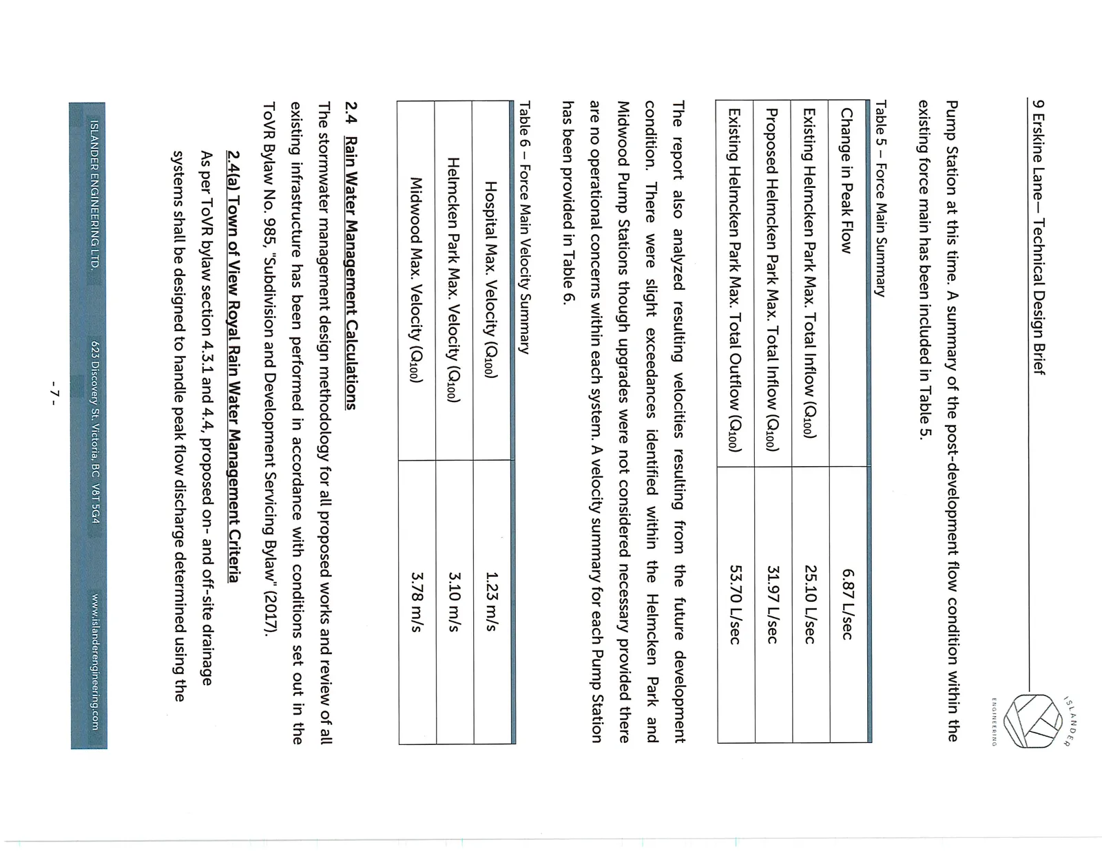
The pumps and forcemain system from the Helmcken Park Pump Station were reviewed to confirm there is sufficient capacity to support the proposed development. The system has a shared forcemain with the Hospital Pump Station and the Milwood Pump Station prior to discharging into the CRD Craigflower Pump Station. From the Sanitary Master Plan Report, we confirm that the future Q100 inflows to the Helmcken Park P.S. show 25.27 L/s, stating the pump station can meet these future demands before any upgrades are needed. From Table 5, with the addition of the proposed development, the peak flow into the Pump Station will be 31.97 L/s. Because this flow is less than the ultimate capacity of the Pump Station, 54.79 L/s, no upgrades are needed to the existing pumps in the Helmcken Park Pump Station at this time. A summary of the post-development flow condition within the existing force main has been included in Table 5.
Table 5 – Force Main Summary
| Change in Peak Flow | 6.87 L/sec |
| Existing Helmcken Park Max. Total Inflow (Q100) | 25.10 L/sec |
| Proposed Helmcken Park Max. Total Inflow (Q100) | 31.97 L/sec |
| Existing Helmcken Park Max. Total Outflow (Q100) | 53.70 L/sec |
The report also analyzed resulting velocities resulting from the future development condition. There were slight exceedances identified within the Helmcken Park and Midwood Pump Stations though upgrades were not considered necessary provided there are no operational concerns within each system. A velocity summary for each Pump Station has been provided in Table 6.
Table 6 – Force Main Velocity Summary
| Hospital Max. Velocity (Q100) | 1.23 m/s |
| Helmcken Park Max. Velocity (Q100) | 3.10 m/s |
| Midwood Max. Velocity (Q100) | 3.78 m/s |
2.4 Rain Water Management Calculations
The stormwater management design methodology for all proposed works and review of all existing infrastructure has been performed in accordance with conditions set out in the ToVR Bylaw No. 985, "Subdivision and Development Servicing Bylaw" (2017).
2.4(a) Town of View Royal Rain Water Management Criteria
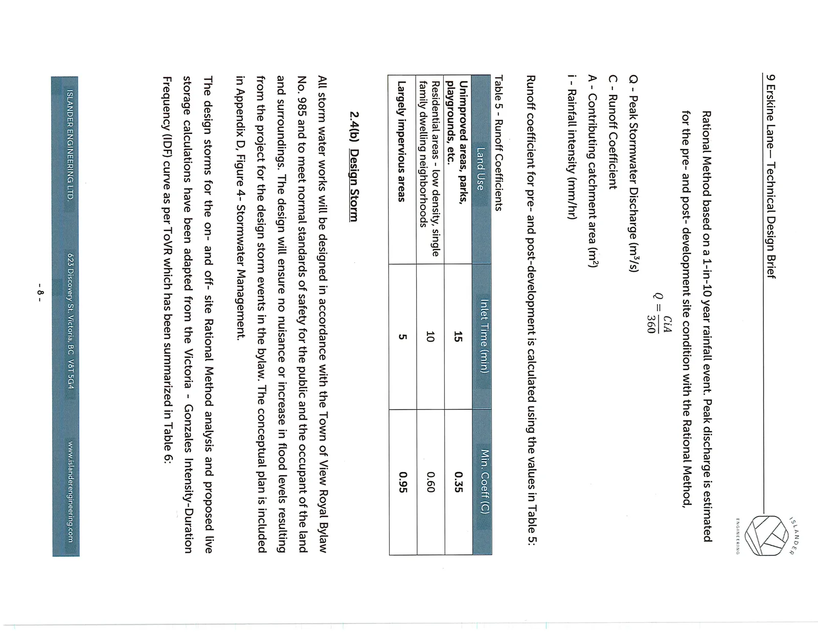
As per ToVR bylaw section 4.3.1 and 4.4, proposed on- and off-site drainage systems shall be designed to handle peak flow discharge determined using the Rational Method based on a 1-in-10 year rainfall event. Peak discharge is estimated for the pre- and post- development site condition with the Rational Method,
$$Q = \frac{CiA}{360}$$
Q - Peak Stormwater Discharge (m³/s) C - Runoff Coefficient A - Contributing catchment area (m²) i - Rainfall intensity (mm/hr)
Runoff coefficient for pre- and post-development is calculated using the values in Table 5:
Table 5 - Runoff Coefficients
| Land Use | Inlet Time (min) | Min. Coeff (C) |
|---|---|---|
| Unimproved areas, parks, playgrounds, etc. | 15 | 0.35 |
| Residential areas - low density, single family dwelling neighborhoods | 10 | 0.60 |
| Largely impervious areas | 5 | 0.95 |
2.4(b) Design Storm
All storm water works will be designed in accordance with the Town of View Royal Bylaw No. 985 and to meet normal standards of safety for the public and the occupant of the land and surroundings. The design will ensure no nuisance or increase in flood levels resulting from the project for the design storm events in the bylaw. The conceptual plan is included in Appendix D, Figure 4- Stormwater Management.
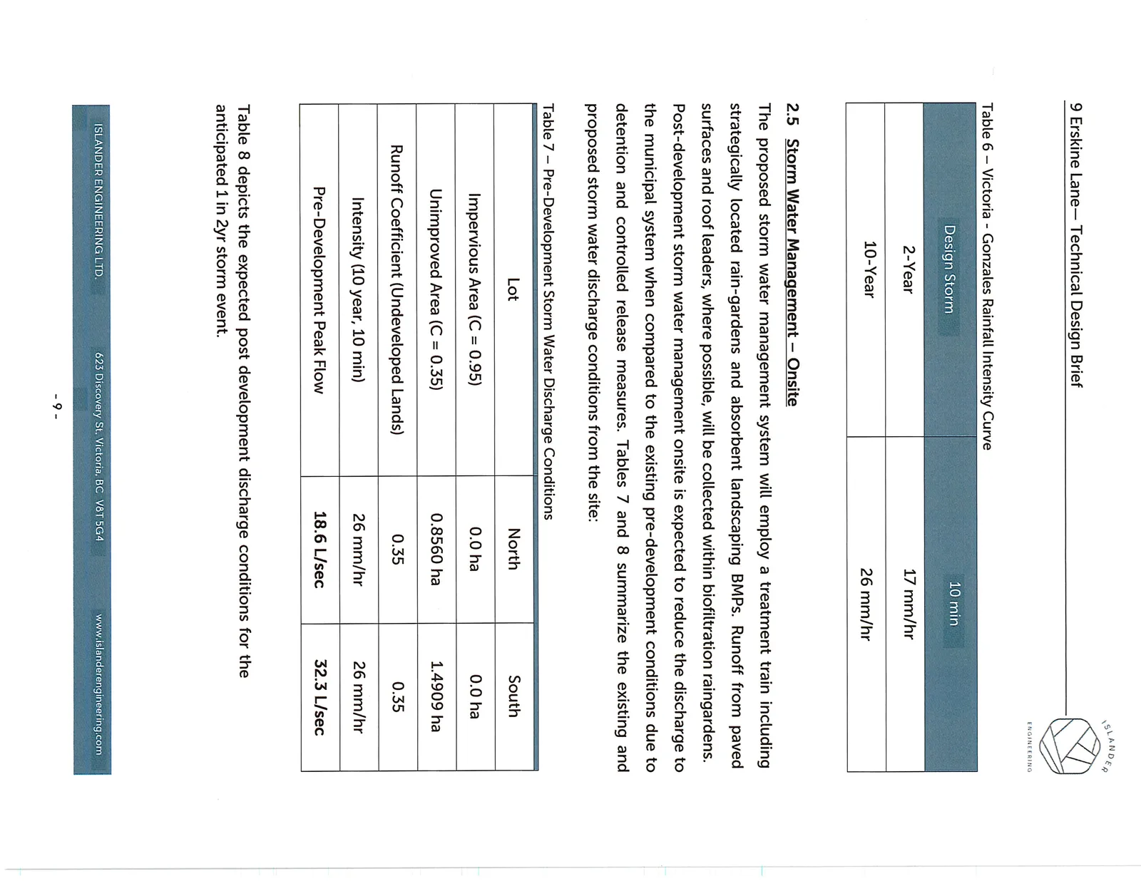
The design storms for the on- and off- site Rational Method analysis and proposed live storage calculations have been adapted from the Victoria - Gonzales Intensity-Duration Frequency (IDF) curve as per ToVR which has been summarized in Table 6:
Table 6 – Victoria - Gonzales Rainfall Intensity Curve
| Design Storm | 10 min |
|---|---|
| 2-Year | 17 mm/hr |
| 10-Year | 26 mm/hr |
2.5 Storm Water Management – Onsite
The proposed storm water management system will employ a treatment train including strategically located rain-gardens and absorbent landscaping BMPs. Runoff from paved surfaces and roof leaders, where possible, will be collected within biofiltration raingardens. Post-development storm water management onsite is expected to reduce the discharge to the municipal system when compared to the existing pre-development conditions due to detention and controlled release measures. Tables 7 and 8 summarize the existing and proposed storm water discharge conditions from the site:
Table 7 – Pre-Development Storm Water Discharge Conditions
| Lot | North | South |
|---|---|---|
| Impervious Area (C = 0.95) | 0.0 ha | 0.0 ha |
| Unimproved Area (C = 0.35) | 0.8560 ha | 1.4909 ha |
| Runoff Coefficient (Undeveloped Lands) | 0.35 | 0.35 |
| Intensity (10 year, 10 min) | 26 mm/hr | 26 mm/hr |
| Pre-Development Peak Flow | 18.6 L/sec | 32.3 L/sec |
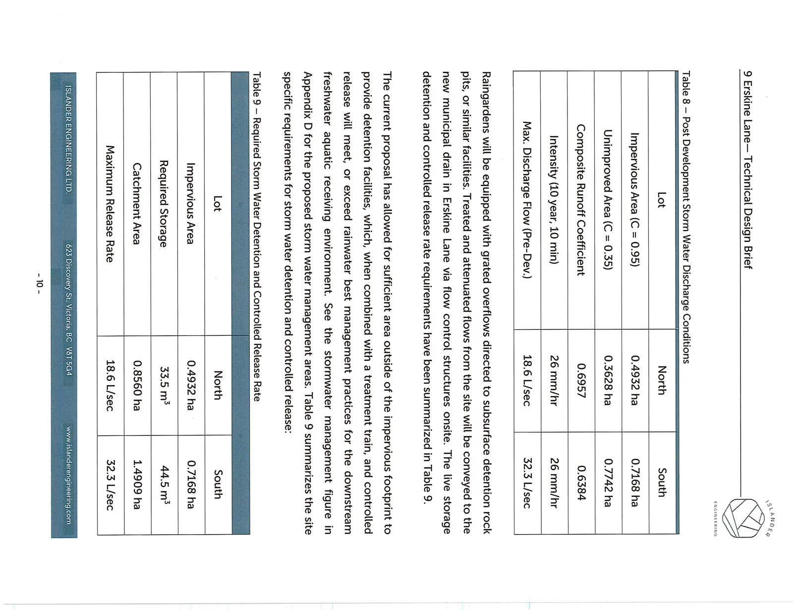
Table 8 depicts the expected post development discharge conditions for the anticipated 1 in 2yr storm event.
Table 8 – Post Development Storm Water Discharge Conditions
| Lot | North | South |
|---|---|---|
| Impervious Area (C = 0.95) | 0.4932 ha | 0.7168 ha |
| Unimproved Area (C = 0.35) | 0.3628 ha | 0.7742 ha |
| Composite Runoff Coefficient | 0.6957 | 0.6384 |
| Intensity (10 year, 10 min) | 26 mm/hr | 26 mm/hr |
| Max. Discharge Flow (Pre-Dev.) | 18.6 L/sec | 32.3 L/sec |
Raingardens will be equipped with grated overflows directed to subsurface detention rock pits, or similar facilities. Treated and attenuated flows from the site will be conveyed to the new municipal drain in Erskine Lane via flow control structures onsite. The live storage detention and controlled release rate requirements have been summarized in Table 9.
The current proposal has allowed for sufficient area outside of the impervious footprint to provide detention facilities, which, when combined with a treatment train, and controlled release will meet, or exceed rainwater best management practices for the downstream freshwater aquatic receiving environment. See the stormwater management figure in Appendix D for the proposed storm water management areas. Table 9 summarizes the site specific requirements for storm water detention and controlled release:
Table 9 – Required Storm Water Detention and Controlled Release Rate
| Lot | North | South |
|---|---|---|
| Impervious Area | 0.4932 ha | 0.7168 ha |
| Required Storage | 33.5 m³ | 44.5 m³ |
| Catchment Area | 0.8560 ha | 1.4909 ha |
| Maximum Release Rate | 18.6 L/sec | 32.3 L/sec |
Minimal overland flow is expected to reach the site from adjacent properties. Flow originating from the north is expected to be intercepted by the existing undeveloped land.
2.6 Storm Water Management – Offsite
The offsite drainage is controlled by the existing profile of Erskine Lane. This profile divides the site into two separate drainage systems as shown in Appendix A.
The north portion of the site flows into an existing ditch along the east side of Erskine Lane, flowing north, which enters into an existing culvert that appears to run under Erskine Lane. More research will need to be completed as there is no discernable outlet to this culvert. The south portion of the site will connect into an existing storm water infrastructure running parallel to Erskine Lane. The municipal system conveys the storm water to a discharge point in Craigflower Creek, approximately 135m to the south. As part of frontage improvements associated with this development, the existing ditches fronting the site will be enclosed in an extension of the existing storm systems. Curb/gutter and catch basins will also be installed on the east side of Erskine Lane fronting the site to capture road runoff.
Following the construction of detention and controlled release systems for storm water discharge from impervious surfaces, the overall peak discharge rate from the site will be lower than the pre-development conditions, therefore no upgrades to the downstream storm water infrastructure are expected to be required. The onsite detention facilities will attenuate the peak flow below pre-development conditions, negating the need for downstream upgrades.
2.7 Hydro/Tel/Cable/Gas
Electrical, communications and natural gas infrastructure is available within the Erskine Lane Right of Way. Connection details and potential upgrades will be assessed through the detailed design phase.
2.8 Transportation, Road Access and Egress
Two 7.0m wide driveways will provide access from Erskine Lane to the internal parking areas which serve visitors and residents, as well as the pickup and drop off locations for each building. The existing paved width of Erskine Lane is approximately 7.8m which will be increased to 8.5m as per Town of View Royal standard road detail VRSD-R10 which includes a 2.0m sidewalk, curb and gutter along the site frontage of Erskine Lane. No upgrades are anticipated along Watkiss Way but a review of the existing traffic study for the area will need to be completed prior to re-zoning.
3 CLOSURE
The above design brief for the proposed development located at 9 – Erskine Lane in View Royal, BC has been prepared by,
ISLANDER ENGINEERING LTD.
Please contact the undersigned with any questions. Yours Truly,
Rob Johnston, CTech. Project Design Technician
Mike Achtem, P.Eng. Principal, Civil Engineer 30 Oct 2019
Document Images
(12)